Securitron M380BDC, M380BDC2, M380BDX, M380BDCX, M380BDC2X Installation Instructions
Open the original PDF document
View PDF

MAGNALOCK® M380BDC/M380BDC2/M380BDX/ M380BDCX/M380BDC2X
Installation Instructions
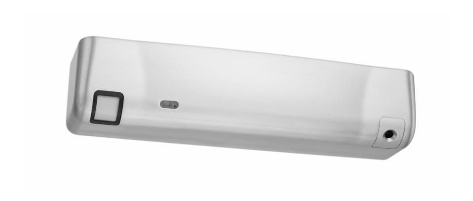
Table of Contents
| Warranty | 3 |
|
Package Contents
|
4 |
|
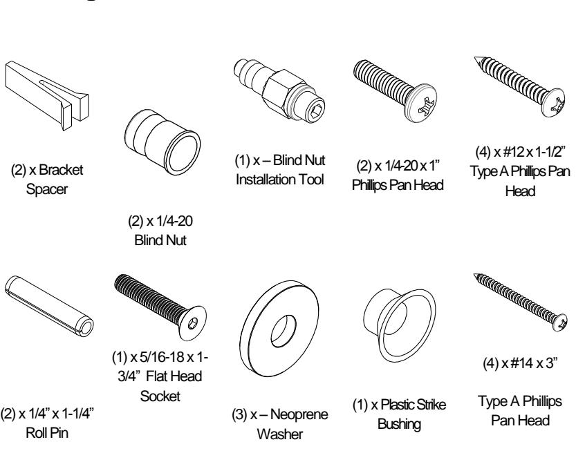
Mounting Hardware
|
4 |
|
Recommended Tools
|
5 |
|
Specifications
|
5 |
|
Magnalock Preparation and Installation
|
6 |
| Performing a Pre-Installation Survey | 6 |
| Positioning the Camera and PIR REX Module Locations in the Magnalock | 6 |
|
Preparing the Magnalock
|
9 |
|
Locating and Setting the Components
|
10 |
| Documenting the Configuration Settings | 15 |
| Installing the Magnalock | 17 |
| Installing the Strike | 21 |
| Assembling the Lock to the Bracket and Adjusting, as Necessary | 25 |
| Performing Final Installation | 27 |
| Performing the Final Wiring | 28 |
|
Magnalock Operation With Access Control System
|
32 |
|
Magnalock Operation With Local Control
|
33 |
| Magnalock Maintenance | 33 |
| Proper Cleaning Methods | 33 |
|
Troubleshooting Guide
|
34 |
|
LED Error Codes
|
35 |

YouTube Channel: SecuritronAccess Watch the overall installation http://tinyurl.com/M380video
Warranty
The MAGNALOCK® series of locks are covered by the MagnaCare® lifetime replacement no fault warranty. No registration is required. Product will be replaced forever, for any reason, including but not limited to installation error, vandalism, or act of God. Replacement product is shipped at Securitron's expense next day air if needed.
For more information, visit www.securitron.com
Package Contents
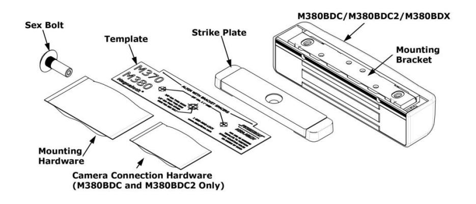
Mounting Hardware
Recommended Tools
Masking Tape #1 and #2 Phillips Hammer
Screwdrivers
Measuring Device 1/2" Open End or Crescent Pencil/Pen
Wrench
Center Punch Wire Strippers/Cutter Multimeter
Fish Tape or Lead
Wire
3/16" Hex (Allen) Wrench
Drill bits: 3/16", 7/32" (wood frames only), 3/8", 1/2"
Specifications
Physical Size :
Height: 2.20" [56mm] Depth: 2.45" [62mm] Length: 10.00" [254mm]
Shipped Weight :
Weight: 6.5 lb Holding Force (Maximum):
600 lbs [272 kg]
UL Tested Ratings :
Static Holding Force: 500 lbs [227 kg]
Dynamic Holding Force:
50 ft-lbs [68 J]
Endurance: 250,000
cycles
Input Voltage:
12/24 VDC. Power must be at least Rectified and Filtered to meet minimum electrical specifications. AC, Half Wave, and Full Wave power is unacceptable.
Magnalock Current
12 VDC/550 mA
(±10%)
24 VDC/300 mA
(±10%)
Optional Camera Current
12 VDC/200 mA
(±10%) 24 VDC/80 mA (±10%)
Optional Passive Infrared (PIR) Current
12 VDC/25 mA (±10%) 24 VDC/10 mA (±10%)
Mechanical Electrical Environmental (Recommended)
Operating Temperature 32ºF to 110ºF [0ºC to 43ºC]
Humidity
10% to 90% RH
Camera Specifications
Color Version:
Horizontal Resolution: 520 TV
Lines
Video Output: 1 VP-P, 75Ω Minimum Illumination: 1.5 LUX Black and White Version: Horizontal Resolution: 420 TV
Lines
Video Output: 1 VP-P, 75Ω Minimum Illumination: 0.1 LUX
Magnalock Preparation and Installation
Performing a Pre-Installation Survey
-
1. Before installing the Magnalock, DETERMINE and ASSESS the mounting location for the following:
- Physical strength of the frame— it should be strong enough to meet or exceed the holding force of the Magnalock.
- Frame and vicinity— it should offer protection for the wiring to prevent vandalism.
- Door inspection—it should be inspected for any obstacles that may interfere when mounting the strike plate.
- Proper mounting—The Magnalock M380 comes with factory default mounting for use with an outswing door. Securitron should be contacted for available brackets for other installation configurations.
Positioning the Camera and PIR REX Module Locations in the Magnalock
- NOTE 1: The physical position of the camera or PIR REX Module may be reconfigured for either end of the Magnalock, as desired.
- NOTE 2: If the Magnalock is equipped with both camera and PIR, each module position may be reversed from the factory default positions (see Figure 1, "Camera and PIR Reversing."
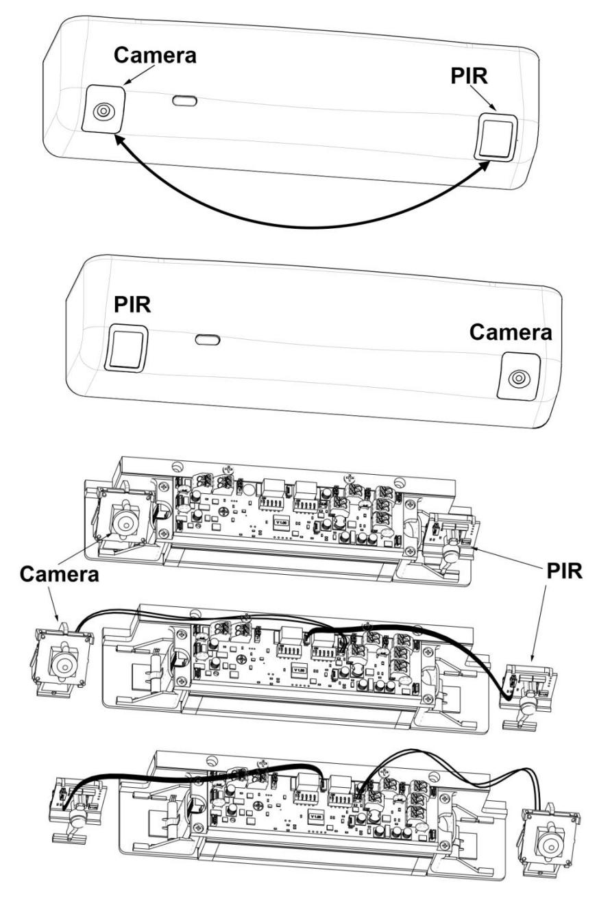
Figure 1. Camera and PIR Reversing
1. To remove or install a module, COMPRESS the legs of the support bracket and SLIDE the module bracket in or out of the retaining rails (see Figure 2, "Removing and Installing a Module").
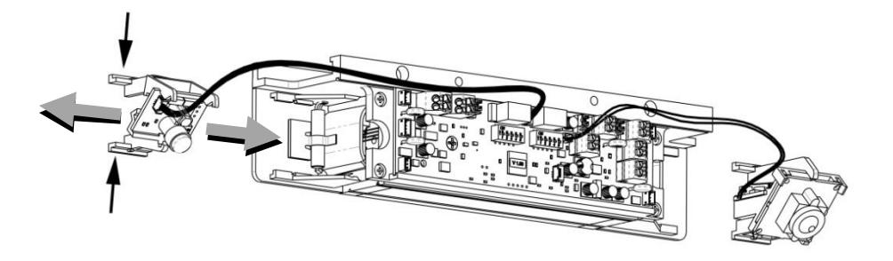
Figure 2. Removing and Installing a Module
2. REMOVE, REPOSITION, and REINSTALL the module inserts in the cover, as necessary, using a #1 Phillips screwdriver (see Figure 3, "Removing, Repositioning, and Reinstalling the Module Inserts."
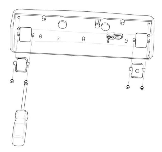
Figure 3. Removing, Repositioning, and Reinstalling the Module Inserts
Preparing the Magnalock
NOTE: Removing the cover provides access to the circuit board and on the back of the magnet.
- 1. Using a Phillips screwdriver, REMOVE the two (2) screws securing the cover, as shown in Figure 4, "Removing the Cover Screws."
- 2. SET the screws aside to re-attach the cover later.
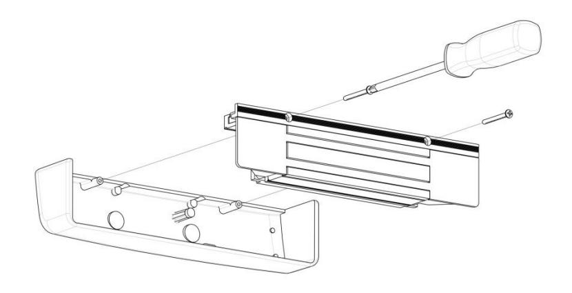
Figure 4. Removing the Cover Screws
Locating and Setting the Components
1. LOCATE and SET the components in the M380 using Figure 5, "Component Locations," and Table 1, "Component Label, Name, Selection, and Position."
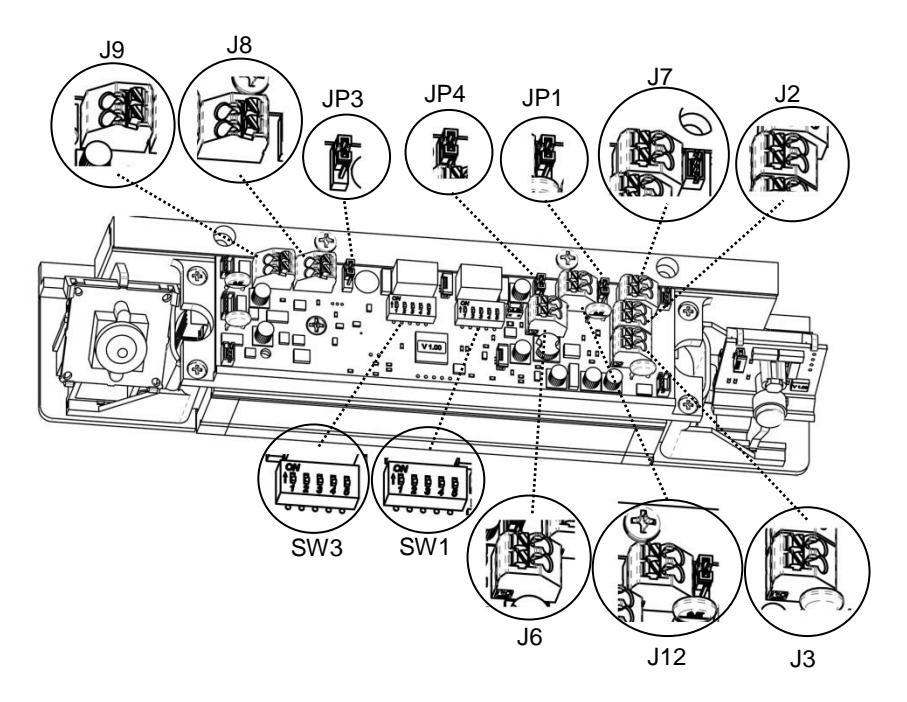
Figure 5. Component Locations

YouTube Channel: SecuritronAccess Component Configuration http://tinyurl.com/M380video1
Table 1. Component Label, Name, Selection, and Position
| Component Label | Component Name | Selection | Position | |
|---|---|---|---|---|
| SW3 |
DIP Switch SW3.1:
LED Enable |
ON = LED
ENABLED (default setting) |
Position 1 ON
(default) |
|
|
Position 1 setting of
the DIP switch enables or disables the display of the LED for lock status. |
OFF = LED
DISABLED |
Position 1 OFF | ||
| SW3 |
DIP Switch SW3.2:
LED Color Select |
ON = SECURE
= RED |
Position 2 ON | |
|
Position 2 setting of
the DIP switch controls the color of the LED output. Output options are red or green. |
OFF =
SECURE = GREEN (default setting) |
Position 2 OFF
(default) |
||
| SW3 |
DIP Switch SW3.3,
SW3.4: |
1/2 second
delay (default) |
Position
3 OFF |
Position
4 OFF |
|
NOTE: If the
system is using an access control |
3 second delay |
Position
3 OFF |
Position
4 ON |
|
|
system, the relock
timer must be set to a minimum time. |
7 second delay |
Position
3 ON |
Position
4 OFF |
|
|
Relock Delay
Timer: |
||||
|
The Auto Relock
Delay can be adjusted by selecting a time delay with position 3 and position 4 of SW3. |
15 second
delay |
Position
3 ON |
Position
4 ON |
|
| Component Label | Component Name | Selection | Position | ||
|---|---|---|---|---|---|
| SW3 | DIP Switch SW3.5: | PIR Model | Position 5 ON | ||
|
PIR Model
Position 5 is set by the factory. This switch should not be changed |
Non-PIR Model | Position 5 OFF | |||
| SW1 |
DIP Switch SW1.1:
PIR Sensitivity |
Medium
Sensitivity (default setting) |
Position 1 OFF
(default) |
||
|
Position 1 setting of
the DIP switch sets the PIR Sensitivity. |
High Sensitivity | Position 1 ON | |||
| SW1 |
DIP Switch SW1.2,
1.3: |
Wide Beam
(default) |
Position
2 OFF |
Position
3 OFF |
|
|
PIR Cone
Adjustment |
Narrow Beam |
Position
2 ON |
Position
3 ON |
||
|
Positions 2 and 3 of
SW1 adjust the PIR sensing cone. |
Position
2 ON |
Position
3 OFF |
|||
|
Narrow Plus
Right |
Position
2 OFF |
Position
3 ON |
|||
| SW1 |
DIP Switch SW1.4:
PIR Ambient Light Compensation |
Ambient Light
Compensation Off (default) |
Position
4 OFF |
Position
4 OFF |
|
|
Can be enabled with
SW1.4 |
Ambient Light
Compensation ON |
Position
4 ON |
Position
4 ON |
||
| Component Label | Component Name | Selection | Position |
|---|---|---|---|
| SW1 |
DIP Switch SW1.5:
External PIR Input |
DISABLE
External PIR Input |
Position 5 OFF
(default) |
|
External input at J6
can be enabled at SW1.5 |
ENABLE
External PIR Input |
Position 5 ON | |
| JP1 |
Jumper 1: Alternate
(REX) Output A 3-pin jumper that controls the output setting for Alternate (REX) Output at |
(NO) Normally
Open Circuit Open, Circuit closes when REX |
|
| Terminal Block J7. |
active
(NC) Normally Closed Circuit Closed when Door is Closed (default setting) |
||
| JP3 |
Jumper 3:
BondSTAT Mode Select |
||
|
A 3-pin jumper that
controls the output setting for the BondSTAT in Terminal Block J8 Position 1 & 2. |
(NC) Normally
Closed Circuit Closed when Door is Closed (default setting) |
||
| Component Label | Component Name | Selection | Position |
|---|---|---|---|
| JP4 |
Jumper 4:
Door Position Mode Select |
(NO) Normally
Open Circuit Open when Door is Closed |
|
|
A 3-pin jumper that
controls the output setting for the Door Position Switch (DPS) in Terminal Block J12 Position 1 & 2. |
(NC) Normally
Closed Circuit Closed when Door is Closed (default setting) |
||
| J9 |
Terminal Block 9
Tamper Switch |
signal which changes state as
Closed with cover in place). |
A 2-wire terminal block providing a
determined when the cover is sensed to be removed. (Circuit is Normally |
| J3 |
Terminal Block 3
Magnalock Input Power |
A 2-wire terminal block providing
connection to a 12 or 24 VDC power supply for the main Magnalock operation. Position 1 = (+) Positive. Position 2 = (-) Negative. |
|
| J2 |
Terminal Block 2
Auxiliary Input Power |
A 2-wire terminal block providing
connection to the power supply for the auxiliary components (PIR and/or Camera). Position 1 = (+) Positive. Position 2 = (-) Negative. |
|
| J8 |
Terminal Block 8
BondSTAT |
A 2-wire terminal block providing a
contact in which (NO/NC) state change is determined by Jumper 3 when the BondSTAT (magnetic bond) is interrupted. |
|
| J12 |
Terminal Block 12
Door Position Switch |
A 2-wire terminal block providing a
contact in which (NO/NC) state change is determined by Jumper 4 based on the magnet's contact with the strike plate. |
|
| Component Label | Component Name | Selection | Position |
|---|---|---|---|
| J6 |
Terminal Block 6
Alternate Input |
A 2-wire terminal block providing a
dry contact connection for external control input. |
|
| J7 |
Terminal Block 7
Alternate (REX) Output |
A 2-wire terminal block provides a
connection for an alternate output. |
|
|
Video Connection
(Camera Interface PCB) |
Terminal Block
Connection for Camera Signal |
The included Balun and BNC cable
adapter can be used to route wiring through either side of the Magnalock housing for connection to a surveillance system. |
|
Documenting the Configuration Settings
NOTE: The Board Settings are now complete.
1. COPY the settings onto the adhesive-backed circuit board settings label enclosed with the mounting hardware packet(see Figure 6, "M380 Settings").
| M380 Settings |
www.securitron.com
1-800-624.5625 |
|---|---|
|
DIP Switch 3 (SW3.1) LED Enable
DIP Switch 3 (SW3.2) LED SECURE Color *Jumper 3 (JP3) Bond Select Mode *Jumper 4 (JP4) Door Position Mode |
ON=ENABLED OFF=DISABLED ON=RED OFF=GREEN 1-2=NC 2-3=NO 1-2=NC 2-3=NO |
| * DIP Switch 3 (SW3.3) Auto Relock Delay *(SW3.4 and SW3.5) Delay (in seconds) * available on M380BD models only | ON=ENABLED OFF=DISABLED 1/2 3 7 15 |
Figure 6. M380 Settings
- NOTE 1: The figure above shows the Default settings. Settings may vary based on checklist.
- NOTE 2: The settings information is required if the Magnalock needs to be inspected, serviced, or replaced.
- 2. COMPLETE the label and AFFIX to the inside cover of the Magnalock (see Figure 7, "Magnalock Settings Label."
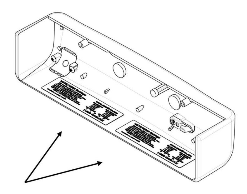
Figure 7. Magnalock Settings Labels
Installing the Magnalock
1. REMOVE the two (2) screws securing lock to mounting bracket and SLIDE the bracket from the top of the lock chassis (see Figure 8, "Removing the Securing Screws").
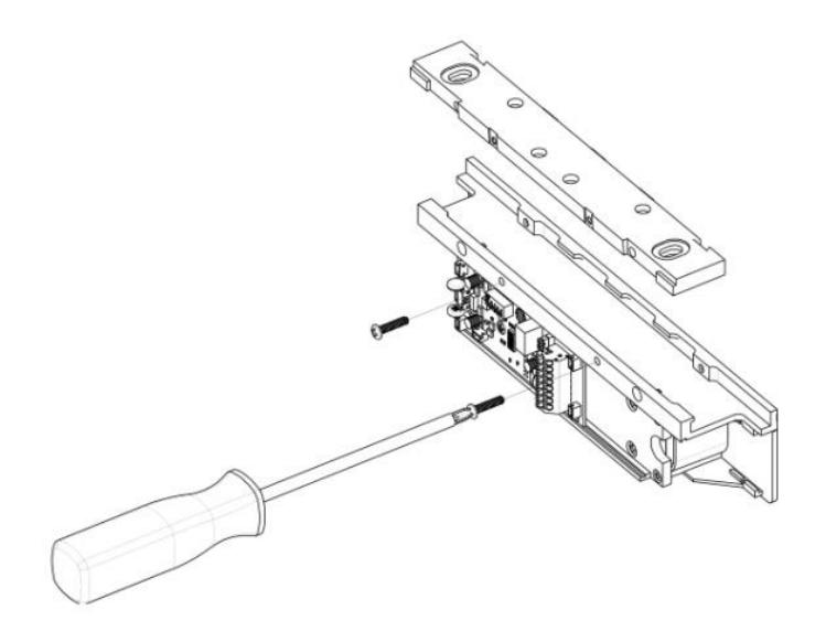
Figure 8. Removing the Securing Screws
2. PINCH and INSERT spacers flush into the dovetail slots of the lock-mounting bracket(see Figure 9, "Inserting the Spacers").
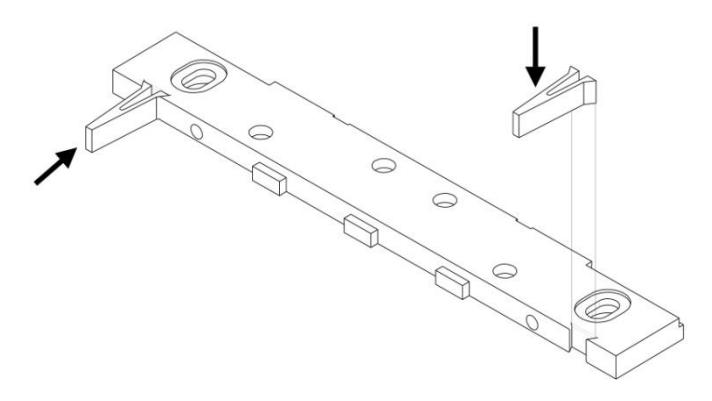
Figure 9. Inserting the Spacers
-
3. PERFORM the following to mark the mounting holes.
- a. PROTECT the door and frame surfaces from any possible damage during marking and drilling by using masking tape.
- b. PLACE the lock bracket on the secure side of the door against the frame stop, towards the side of the door that does not have hinges, and has a minimum of 7/8" clearance from the frame.
- c. CLOSE the door and ADJUST the bracket so that the spacers rest against the door.
- d. MARK the frame through the two (2) oblong bracket mounting holes (see Figure 10, "Marking the Frame").
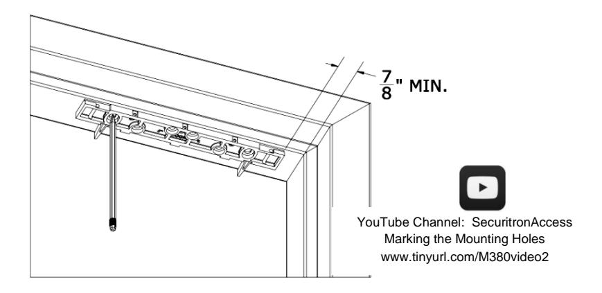
Figure 10. Marking the Frame
- 4. MARK the frame for wire feed-through hole at the end closest to where the wire run will be accessed.
- 5. ENSURE these holes are toward the rear edge of the mounting bracket and adjacent to the end of the bracket (see Figure 11, "Position of Wire Feed-Through Holes").
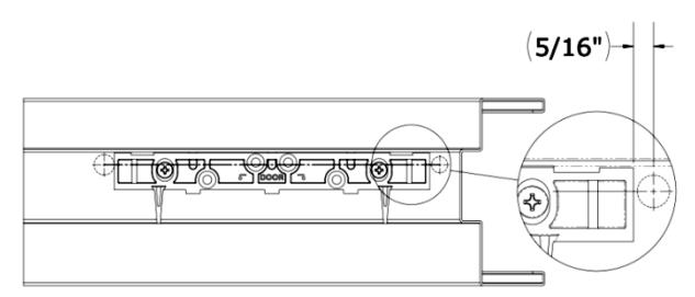
Figure 11. Position of Wire Feed-Through Holes
6. REMOVE mounting bracket from frame when drilling holes.
NOTE 1: Steps 7–9c are performed if installing on metal door frame.
NOTE 2: Steps 10–11 are performed if installing on a wood door frame.
- 7. DRILL two (2) 3/8" diameter holes at bracket-mounting hole marks (see Figure 12, "Drilling the Bracket Mounting Holes"); DO NOT oversize.
- 8. USE a step bit or pilot hole first to ensure a snug fit for the blind nuts.
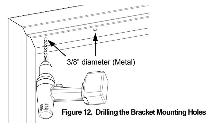
NOTE: Blind nuts provide a highly secure and tamper resistant system for mounting and are the mounting hardware provided for this unit.
-
9. INSTALL blind nuts into each 3/8" diameter hole using the provided tool(see Figure 13, "Installing the Blind Nuts").
- a. HOLD the collapsing nut with a ½" box end wrench.
- b. MAINTAIN pressure on the mounting surface, TIGHTEN the cap screw using a 3/16" hex wrench, and COLLAPSE the blind nut.
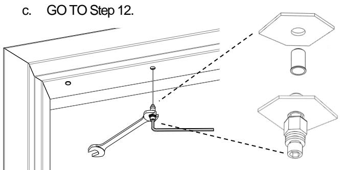
Figure 13. Installing the Blind Nuts

YouTube Channel: SecuritronAccess Blind Nut Installation www.tinyurl.com/M380video3
10. DRILL two (2) 3/16" diameter mounting holes by 1-1/4" deep at bracketmounting hole marks (see Figure 14, "Drilling the Mounting Holes").
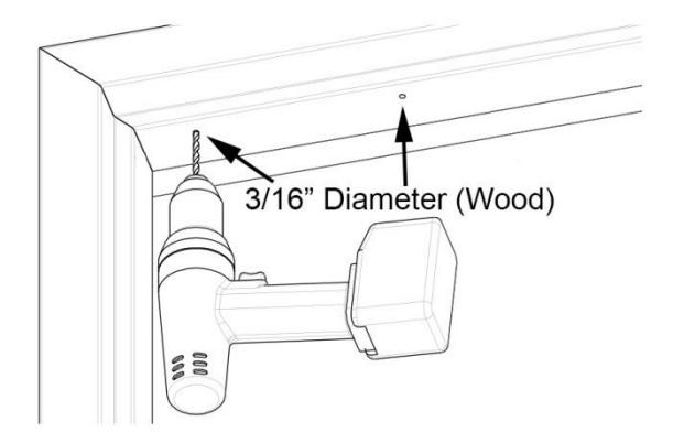
Figure 14. Drilling the Mounting Holes
11. DRILL wire access holes (1/2" recommended), as needed, on one or both sides of the bracket (see Figure 15, "Drilling the Wire Access Holes").
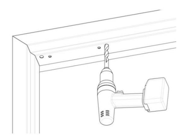
Figure 15. Drilling the Wire Access Holes
12. Temporarily INSTALL the bracket with spacers against the closed door using a Phillips screwdriver (see Figure 16, "Installing the Bracket").
NOTE: Step 13a applies to metal frames.
a. USE two (2) 1/4-20 X 1" Phillips Pan Head Screws and APPLY included thread lock to screw threads.
NOTE: Step 13b applies to wood frames.
b. USE two (2) #12 X 1-1/2" Type A, Phillips Pan Head Screws.
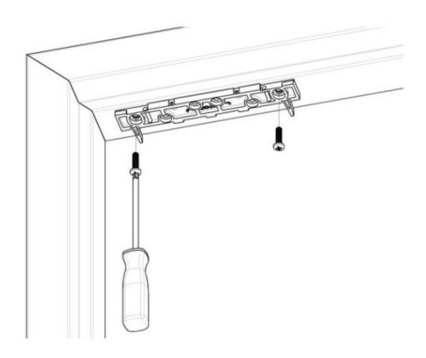
Figure 16. Installing the Bracket
Installing the Strike
- 1. CLOSE the door and PLACE the template between the bracket spacers.
- 2. MARK the strike plate hole locations (see Figure 17, "Marking the Strike Plate Hole Locations").
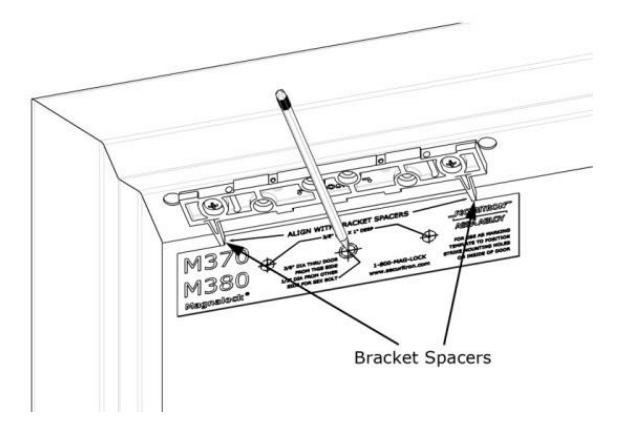
Figure 17. Marking the Strike Plate Hole Locations

YouTube Channel: SecuritronAccess Marking the Strike Plate Hole Locations www.tinyurl.com/M380video4
3. REMOVE the bracket spacers from the bracket.
From INSIDE the door:
- 4. DRILL one (1) 3/8" diameter hole for the sex bolt through the door at the strike mounting center mark.
- 5. DRILL two (2) 3/8" diameter x 1" deep holes at each side mark for the strike alignment roll pins, but DO NOT DRILL through the door (see Figure 18, "Drilling the Inside Door Holes").
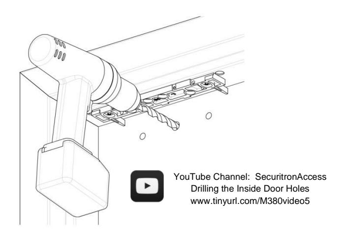
Figure 18. Drilling the Inside Door Holes
From OUTSIDE the door:
- 6. For a Hollow Metal Door , DRILL out the 3/8" diameter strike mounting hole to 1/2" diameter in the outer wall only.
- 7. For a Solid Wood Door , DRILL out 3/8" diameter strike mounting hole to 1/2" diameter; DRILL completely through door (see Figure 19, "Drilling the Outside Door Holes").
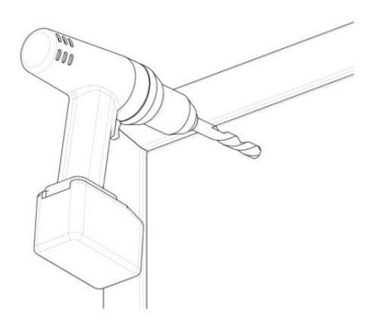
Figure 19. Drilling the Outside Door Holes
-
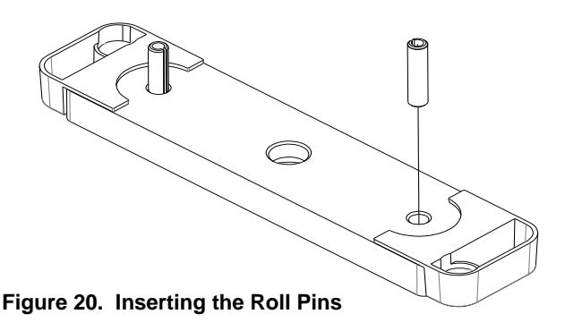
8. PERFORM the following to install roll pins into strike plate.
- a. REMOVE the two (2) roll pins from the hardware packet.
- b. INSERT a roll pin into each of the holes in back of strike.
- c. Gently TAP into place using a hammer (see Figure 20, Inserting the Roll Pins").
NOTE: Figure 21, "Securing the Strike Plate," provides illustration for the following steps.
-
9. PERFORM the following to secure strike plate to the door.
- a. APPLY the included thread lock compound to 5/16-18 X 1-3/4" flat head socket screw.
- b. INSERT the 5/16-18 X 1-3/4" flat head socket screw through the strike bushing, strike plate, two (2) neoprene washers, door and into the sex bolt as illustrated.
- c. TIGHTEN the screw into sex bolt using a 3/16" hex wrench; and while tightening, gently TAP the head of sex bolt until the head sits flush with the door using a hammer.
NOTE: The strike should rock on the neoprene washers for proper function and optimal holding force.
d. DO NOT OVER-TIGHTEN the assembly; the neoprene washers should not be compressed.
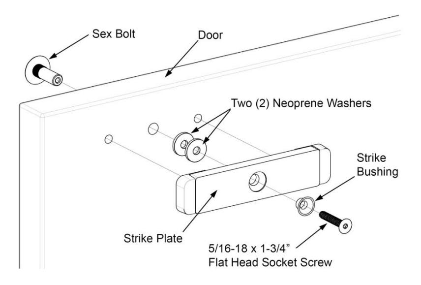
Figure 21. Installing the Strike Plate

YouTube Channel: SecuritronAccess Installing the Strike Plate www.tinyurl.com/M380video6
Assembling the Lock to the Bracket and Adjusting, as Necessary
NOTE: Figure 22, "Assembling the Lock to the Bracket and Adjusting," provides illustration for the following steps.
- 1. LOOSEN the two screws securing the mounting bracket to the door frame so that the bracket can move.
- 2. SLIDE the lock onto the mounting bracket and TEST FIT against the strike plate with the door closed; SLIDE the lock so that the entire face makes contact with the strike plate. 3. MARK back edge of mounting bracket at each end and REMOVE the lock from the bracket.

YouTube Channel: SecuritronAccess Assembling the Lock to the Bracket www.tinyurl.com/M380video7
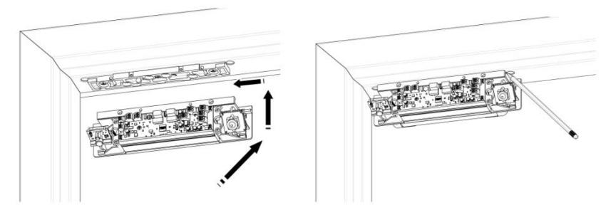
Figure 22. Assembling the Lock to the Bracket and Adjusting
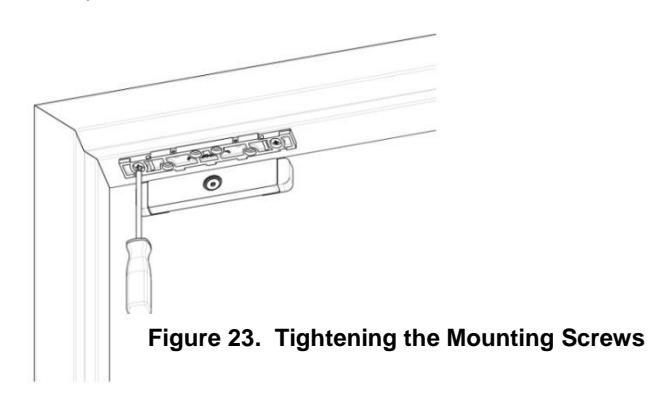
5. ENSURE that the mounting bracket aligns with the marks, and TIGHTEN the mounting screws (see Figure 23, "Tightening the Mounting Screws").
-
6. Using the mounting bracket as a template, DRILL the four remaining holes in the frame for the anchor screws as follows (see Figure 24. Drilling the Anchor Screw Holes"):
- Metal Frames have 3/16" diameter holes.
- Wood Frames have 7/32" diameter holes.
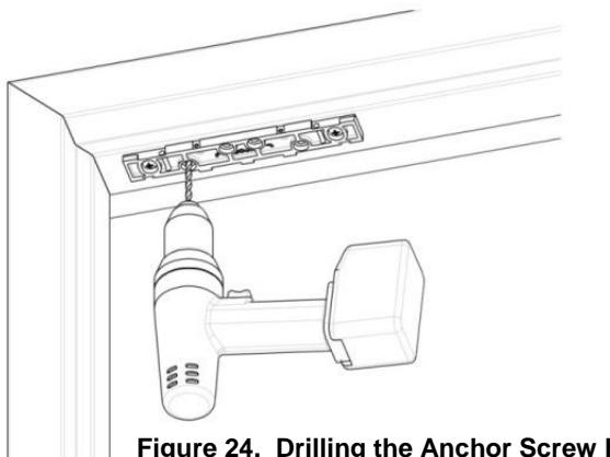
Figure 24. Drilling the Anchor Screw Holes
-
7. INSTALL the four (4) anchor screws using a Phillips screwdriver (see Figure 25, "Installing the Anchor Screws"):
- Metal Frames use #12 X 1-1/2" Type A, Phillips Pan Head Screws
- Wood Frames use #14 X 3" Type A, Pan Head Screws
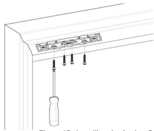
Figure 25. Installing the Anchor Screws
Performing Final Installation
NOTE: The edge of the lock chassis must be flush with the end of the mounting bracket when centered (see inset).
1. INSERT the top of the Magnalock chassis at the end of the mounting bracket, and SLIDE the lock chassis to the center of the bracket (see Figure 26, "Performing Final Installation").
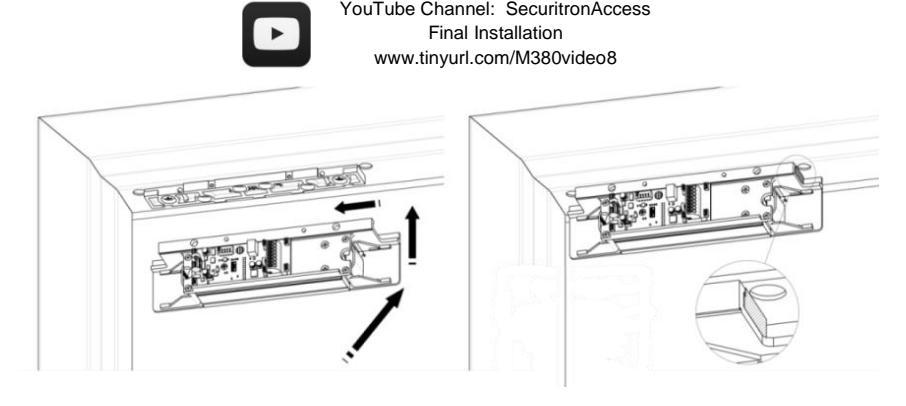
Figure 26. Performing Final Installation
2. INSTALL the two (2) 6-32 X 3/4" Phillips pan head screws to secure the lock chassis to the mounting bracket using a Phillips screwdriver (see Figure 27, "Securing the Lock Chassis to the Mounting Bracket").
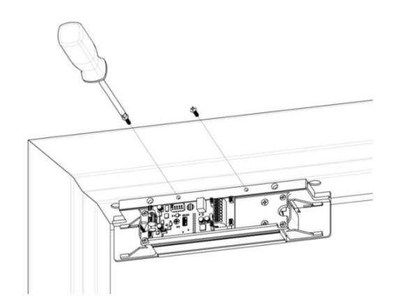
Figure 27. Installing the Lock Chassis to the Mounting Bracket
Performing the Final Wiring
- NOTE 1: End user and installer are liable for Fire and Building code compliance.
- NOTE 2: A small screwdriver has been included to help make connections to the terminal blocks, as required.
- 1. PULL wires/cables through the wire feed-through hole(s) that are drilled in the frame, and CONNECT wiring using the Figure 29, "Wiring for M380 BDC/BDC2," and Figure 30, "Wiring for M380 BDCX/BDC2X/BDX," as guides.
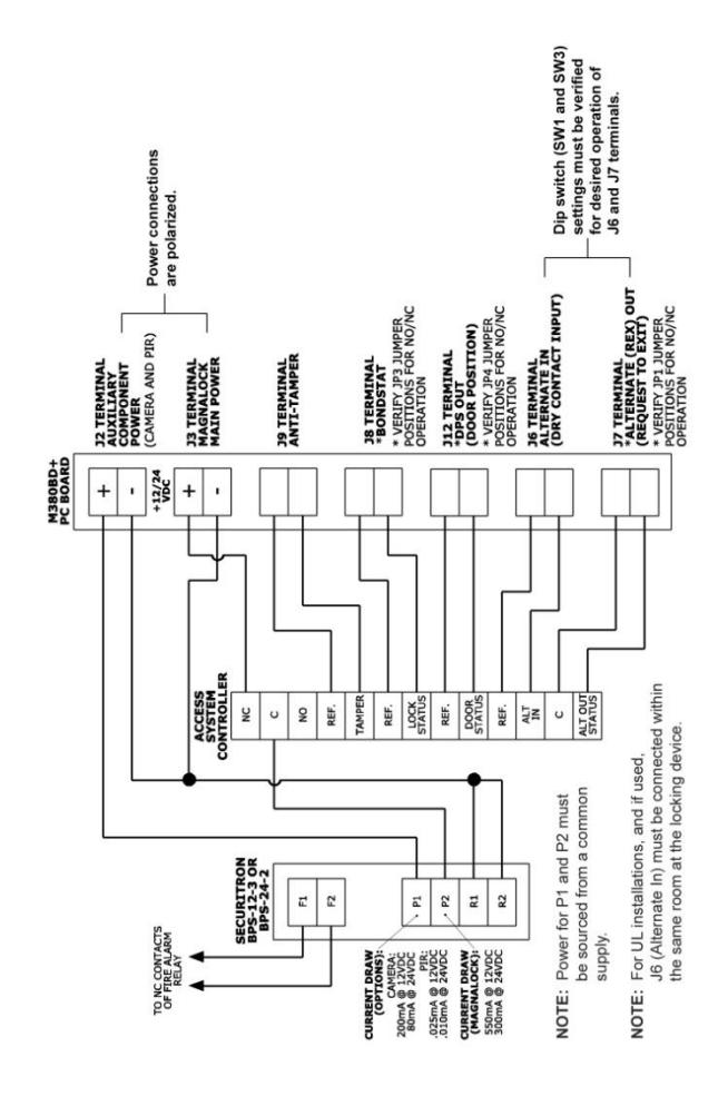
Figure 29. Wiring for M380BDC/BDC2
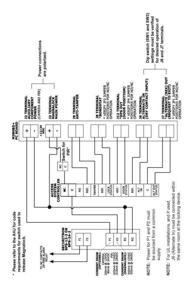
Figure 30. Wiring for M380BDCX/BDC2X/BDX
- NOTE 1: Steps 2–6 are performed for M380 models with the PIR feature.
- NOTE 2: PIR control features are accessed by the DIP Switches SW3 and SW1 settings.
- 2. SET the relock delay timer using DIP Switch SW3, Positions 3 and 4, as required.
NOTE: Figure 31, "PIR Sensitivity and Cone Adjustment," provides illustration to Steps 3 and 4.
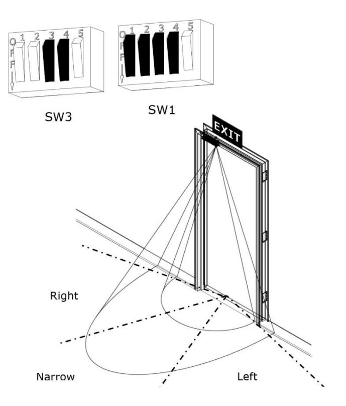
Figure 31. PIR Sensitivity and Cone Adjustment
- 3. SET the PIR sensitivity using DIP Switch SW1, Position 1, as required.
- 4. SET the PIR Cone Adjustment width using DIP Switch SW1, Positions 2 and 3, as required.
- 5. ENABLE or DISABLE the PIR ambient light compensation feature using DIP Switch SW1,Position 4, as required.
- 6. REPOSITION the PIR sensor PC board in the modular bracket, as necessary, for increased range (see Figure 32, "Repositioning the PIR").
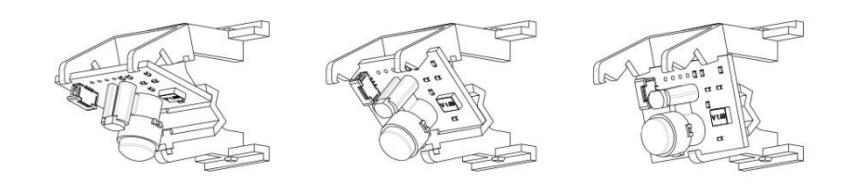
Figure 32. Positioning the PIR
- NOTE 1: Step 7 is performed for M380 models with the camera feature.
- NOTE 2: The camera module features an interface PC board which includes a two-position terminal block.
- NOTE 3: A BNC straight adapter is also included for connections to a male BNC connector(see Figure 30, "Connecting the Camera").
- 7. CONNECT the camera to the security system with a two-wire (twisted pair) from the two-position interface board terminal block to the included video transceiver balun (see Figure 33).
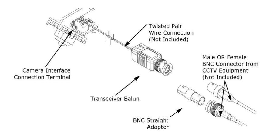
Figure 33. Connecting the Camera
8. After installation and wiring have been completed, RE-INSTALL the lock cover through the lock chassis using the two (2) phillips screws (see Figure 34, "Installing the Lock Cover").
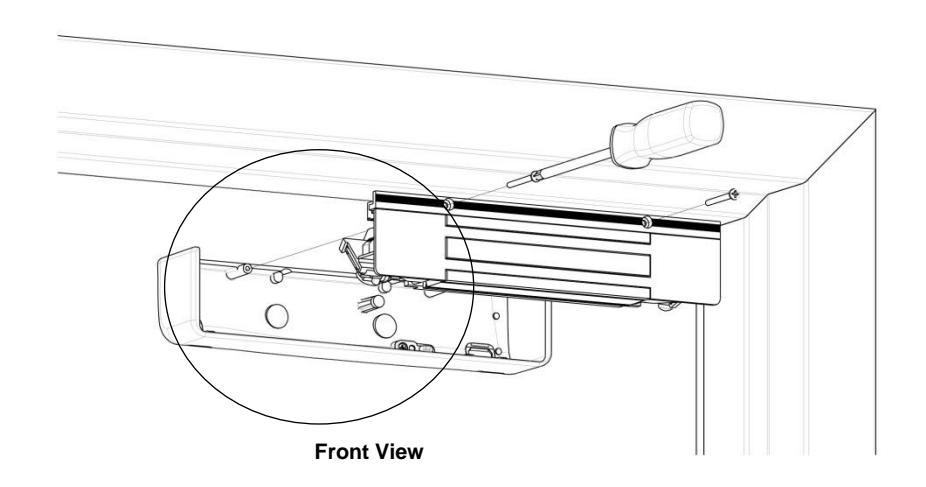
Figure 34. Installing the Lock Cover
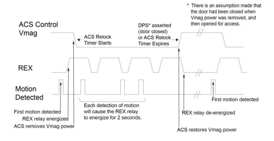
Magnalock Operation With Access Control System
NOTE: The Magnalock relock timer is required to be set to minimum.
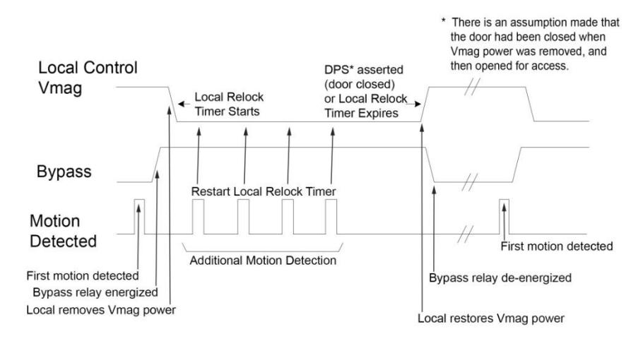
Magnalock Operation With Local Control
NOTE: The Magnalock relock timer is required to be set to minimum.
Magnalock Maintenance
-
1. PERFORM the following to complete a visual inspection.
- a. INSPECT the rubber washers for elasticity and proper pivoting; and TIGHTEN, as required.
- b. INSPECT for build-up of debris on the Magnalock and strike armature.
- c. INSPECT for rust on the Magnalock and strike plate armature; CLEAN, as required.
Proper Cleaning Methods
- 2. APPLY rubbing alcohol onto a clean cloth and thoroughly WIPE DOWN the Magnalock and strike plate armature.
- NOTE 1: Cleaning once a year is recommended.
- NOTE 2: Petroleum-based products should never be used for cleaning.
- NOTE 3: Steel wool-based scrub pads or sandpaper should never be used for cleaning.
- 3. CLEAN every three to six months where rusting occurs.
- 4. USE a plastic dishwashing scrub pad to aid in the removal of rust.
Troubleshooting Guide
| POSSIBLE ISSUES | TROUBLESHOOTING TIPS | ||
|---|---|---|---|
| NOTE: |
When Vaux of a M380 (all M380BDC/C2/X variants) reaches 7.5V,
the lock releases and LV flash commences until the system recovers or Vaux has fallen to a point causing the system to be in a brown-out condition. |
||
| No power or low power | to specification. | CONFIRM voltage and current at Magnalock | |
| NOTE: |
Power must be at least Rectified
and Filtered to meet minimum electrical specifications. AC, Half Wave, and Full Wave power is unacceptable. |
||
| CHECK |
that the DC power source is Full
Wave Rectified. |
||
| Reduced Holding Force | CHECK strike plate position and orientation. | ||
| CLEAN surfaces and CHECK for obstructions. | |||
|
CONFIRM voltage and current at Magnalock
to specification. |
|||
| NOTE: |
Power must be at least Rectified
and Filtered to meet minimum electrical specifications. AC, Half Wave, and Full Wave power is unacceptable. |
||
|
CHECK that the DC power source is Full
Wave Rectified. |
|||
LED Error Codes
NOTE: The position 1 switch of DIP switch SW3 must be set to the ON position (LED ENABLED) for error codes to be visible.
| CODE | STATE | SOLUTION |
|---|---|---|
|
SECURE selected
color, on continuously |
Normal Operation
with Door Closed |
System working normally,
SECURE selected color can be selected with position 2 switch of SW3. See page 4. |
|
NON-SECURE
selected color, on continuously |
Normal Operation
with Door Open |
System working normally. |
|
RED/GREEN
continuous flash |
Processor Error |
CHECK all connections, if error
persists replace unit. |
|
AMBER Continuous
flash |
Low
Voltage Condition (Occurs below 8.2V). MagnaLock is disabled. |
CHECK voltage and current at
Magnalock connections. CHECK DC Power Source is Full Wave Rectified. |
| Solid AMBER |
Any situation, DPS
or Bond. |
CHECK strike plate position
and orientation. CLEAN surfaces and check for obstructions. |
| Off | LED disabled |
CHECK voltage and current at
Magnalock connections. CHECK that LED is enabled with position 1 switch of SW3 is in the OFF position. |
Securitron
Phoenix, AZ Tel: 1.800.624.5625
Mon-Fri: 6:00am - 4:00pm PDT
Fax: 1.800.232.7329
www.securitron.com techsupport@securitron.com