ROFU 2960 Series Electric Dropbot & Electromechanical Lock Installation Instructions
Open the original PDF document
View PDF

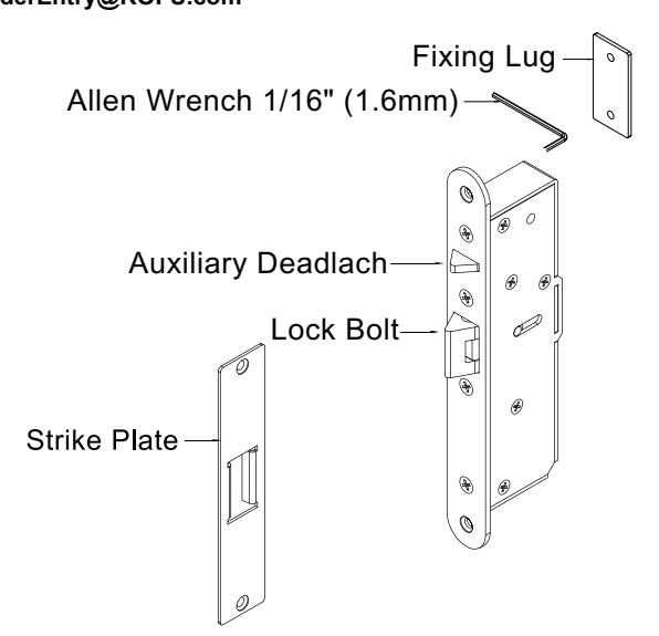
Electric Lock Installtion Instructions
ROFU 2960
ROFU Security International Corp.
6818 S 220th ST Kent, WA 98032 (253) 922-1828 www.ROFU.com OrderEntry@ROFU.com
Operating Voltage: 12~24VDC/AC
Voltage Tolerance: ±10%
Current Draw: 210mA/12VDC, 150mA/24VDC
Lock Mode: Field reversible for fail-safe or fail-secure
Operating Temperature: +14° to +131°F (-10° to +45°C)
Humidity: 0 to 95% Non-Condensing
Lock Bolt Sensor Switch Output: SPDT rated 3A/125VAC
Cycle Test: Up to 1,000,000 cycles
Net Weight: 594g
Application: Horizontal or vertical installation
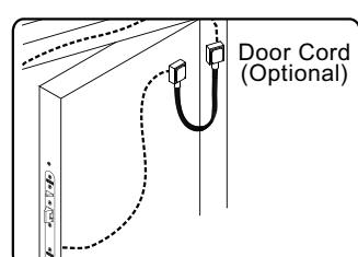
The door cord protects the wiring from damage at the door hinge.
Door Swing Direction
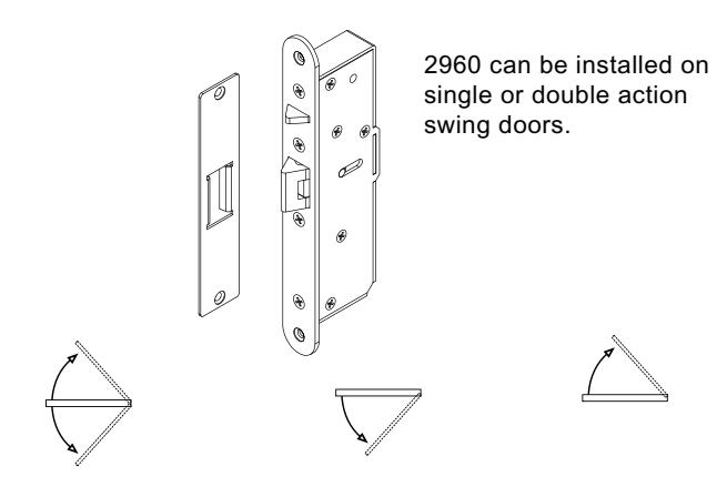
Double Swing Door Single Inswing Door
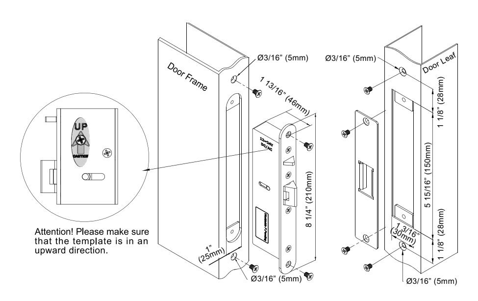
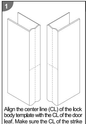
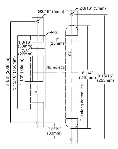
Template
Changing Fail-Safe/Fail-Secure
- 1. Loosen and remove the screw 1.
- 2. Loosen and move the screw 2, and then tighten both screws.
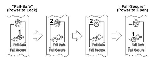
A Caution:
Do not completely loosen screw 2 (as shown in the figure) as the interior solenoid might fall off.
Installing the Crimp Connectors

Use crimper or pliers and press the header of connector down to even position.
Wiring Diagram
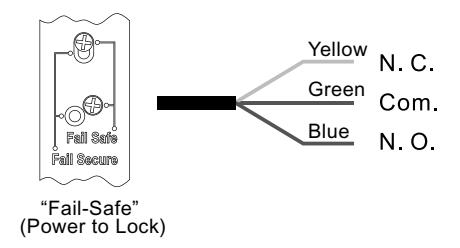
For Fail-Safe Operation
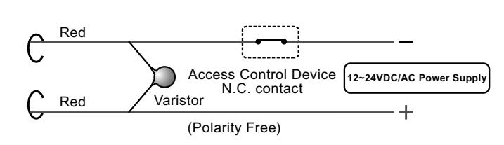
Lock Bolt Sensor Switch Output
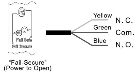
For Fail-Secure Operation
Lock Bolt Sensor Switch Output
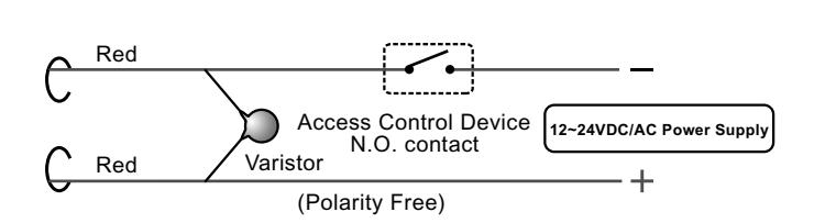
NOTE: The varistor (or diode) must be connected across the terminals of electric locks to protect the electric lock from spikes and surges.