I-SD00472 [9570RC] [125lb Bi-Fold Sliding Door Hardware Set Installation Instructions][4]
Open the original PDF document
View PDF

The 9570RC is for 1-1/8" to 1-3/4" thick panels. Hardware is rated up 125lbs per panel pair. 36" is for 2- Panel Assembly. 48", 60", 72" and 96" are for 4-Panel Assembly.
| Contents: | 2-Pnl | 4-Pnl | |
|---|---|---|---|
| Qty: | Qty: | ||
|
Track (9303HD)
1. Bi-Fold, By-Pass and Pocket Door Box Track |
1 | 1 | |
|
2.
#8 x 1-1/4" PPHW Track Screw |
* | * | |
| Bi-Fold Pivot Set | |||
|
3.
Top Pivot Assembly |
1 | 2 | |
|
4.
Bottom Pivot Assembly |
1 | 2 | |
| 3.5" x 3.5" Hinge (1741) | |||
|
5.
3.5" x 3.5" Hinge (1741) |
3 | 6 | |
|
6.
#9 x ¾" FPHW Hinge Screw |
18 | 36 | |
| Bi-Fold Accessories Parts Bag | |||
|
7.
Wooden Knob |
1 | 2 | |
|
8.
#8 x 1-3/4" TPH Knob Screw |
1 | 2 | |
|
9.
#8 x 2" TPH Knob Screw |
1 | 2 | |
|
10.
Bi-Fold Aligner |
1 | 2 | |
|
11.
#8 x 5/8" PPHW Aligner Screw |
2 | 4 | |
|
12.
Bi-Fold Center Stop Bumper |
1 | 2 | |
| 4-wheel Hanger Parts Bag | |||
|
13.
4-wheel Roller |
1 | 2 | |
|
14.
Hanger Plate |
1 | 2 | |
|
15.
M5.5 x 32mm PPHW Hanger Plate Screw |
2 | 4 | |
*Number of Panels and Track Screws are dependent on the Actual Track Length:
| Actual Track Length | Number of Panels | Number of Track Screws |
|---|---|---|
| 36" | 2 | 4 |
| 48" | 4 | 6 |
| 60" | 4 | 6 |
| 72" | 4 | 6 |
| 96" | 4 | 8 |

1 Prepare the Finished Opening
PANEL HEIGHT = FINISHED OPENING HEIGHT - 2-7/8" ± 1/4"
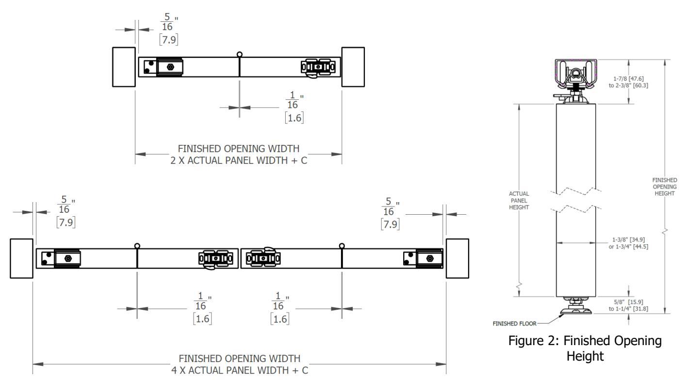
Figure 1: 2-Panel and 4-Panel Finished Opening Width
| Finished Opening Width "C" Values | |||||
|---|---|---|---|---|---|
| 2-Panel | 4-Panel | ||||
| 1-3/8" Thick Panels or Less | 1-3/4" Thick Panels | 1-3/8" Thick Panels or Less | 1-3/4" Thick Panels | ||
| 3/8" | 1/2" | 3/4" | 1" | ||

2 Prepare the Top and Bottom Pivot Assembly
| Bi-Fold Pivot Set (1-159-0010) Contents: |
2-Pnl
Qty: |
4-Pnl
Qty: |
||
|---|---|---|---|---|
| 1. |
Top Pivot Track Bracket -
Top |
1 | 2 | |
| 2. |
Top Pivot Track Bracket -
Bottom |
1 | 2 | |
| 3. | Top Pivot Door Mounting Plate | 1 | 2 | |
| 4. | 1/4"-20 x 1/2" Top Pivot Track Bracket Bolt | 1 | 2 | |
| 5. | 1/4" Internal-External Lock Washer | 1 | 2 | |
| 6. | #8 x 1" PPHW Pivot Mounting Screw | 12 | 24 | |
| 7. | Bottom Pivot Floor Mounting Plate | 1 | 2 | |
| 8. | Bottom Pivot Door Mounting Plate | 1 | 2 | |
| 9. | 5/16"-18 x 1-9/16" Bottom Pivot Adjusting | 1 | 2 | |
| Bolt | ||||
| Figure 3: Top and Bottom Pivot Assembly |

3 Install the Track and Hardware
- Track length should be 1/8" less than the finished opening width
- Place the Top Pivot Track Bracket Top and 4-Wheel Roller loose in the track with the pivot bracket on the pivot side
- Center the track in the opening
- Secure the track with #8 x 1-1/4" PPHW screws
- Install the Top Pivot Track Bracket Bottom, 1/4" Internal-External Lock Washer and 1/4"-20 x 1/2" Top Pivot Track Bracket Bolt onto the Top Pivot Track Bracket - Top
- Move the Top Pivot Bracket Assembly 2-5/16" from the Pivot Side Jamb and loosely hand tighten . Note: This will enable it to slide freely on the track while setting the pivot side panel into the Bottom Pivot Floor Mounting Plate
- At the center of the jamb depth, 2-5/16" from the Pivot Side Jamb, secure the Bottom Pivot Floor Mounting Plate on to the floor with 2ea #8 x 1" PPHW screws as seen in Figure 5
Note: This will allow the Bottom Pivot Floor Mounting Plate to be adjusted after the door panels are placed
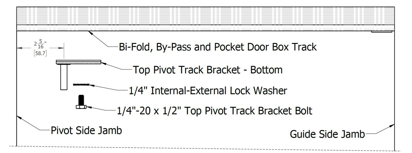
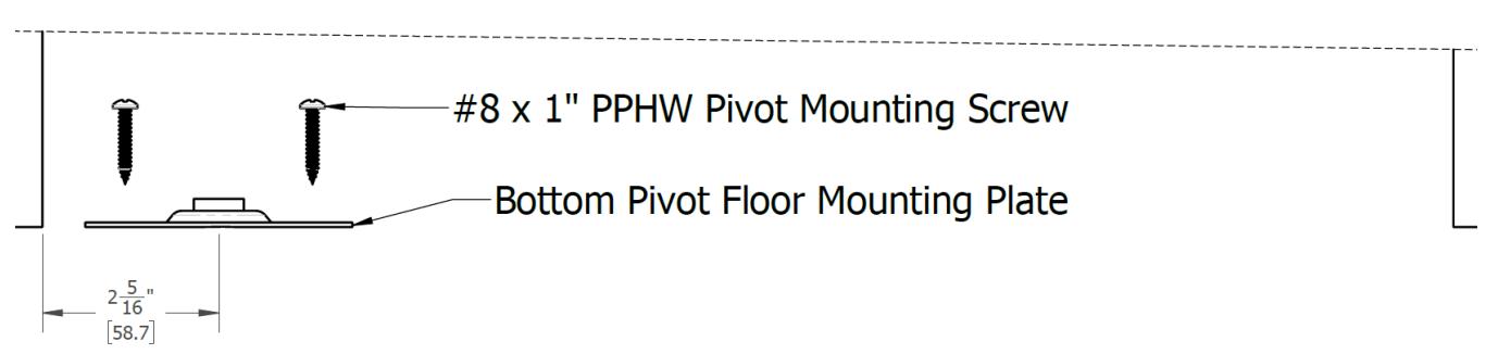
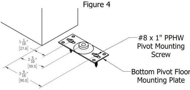
Figure 5

4 Prepare the Panels
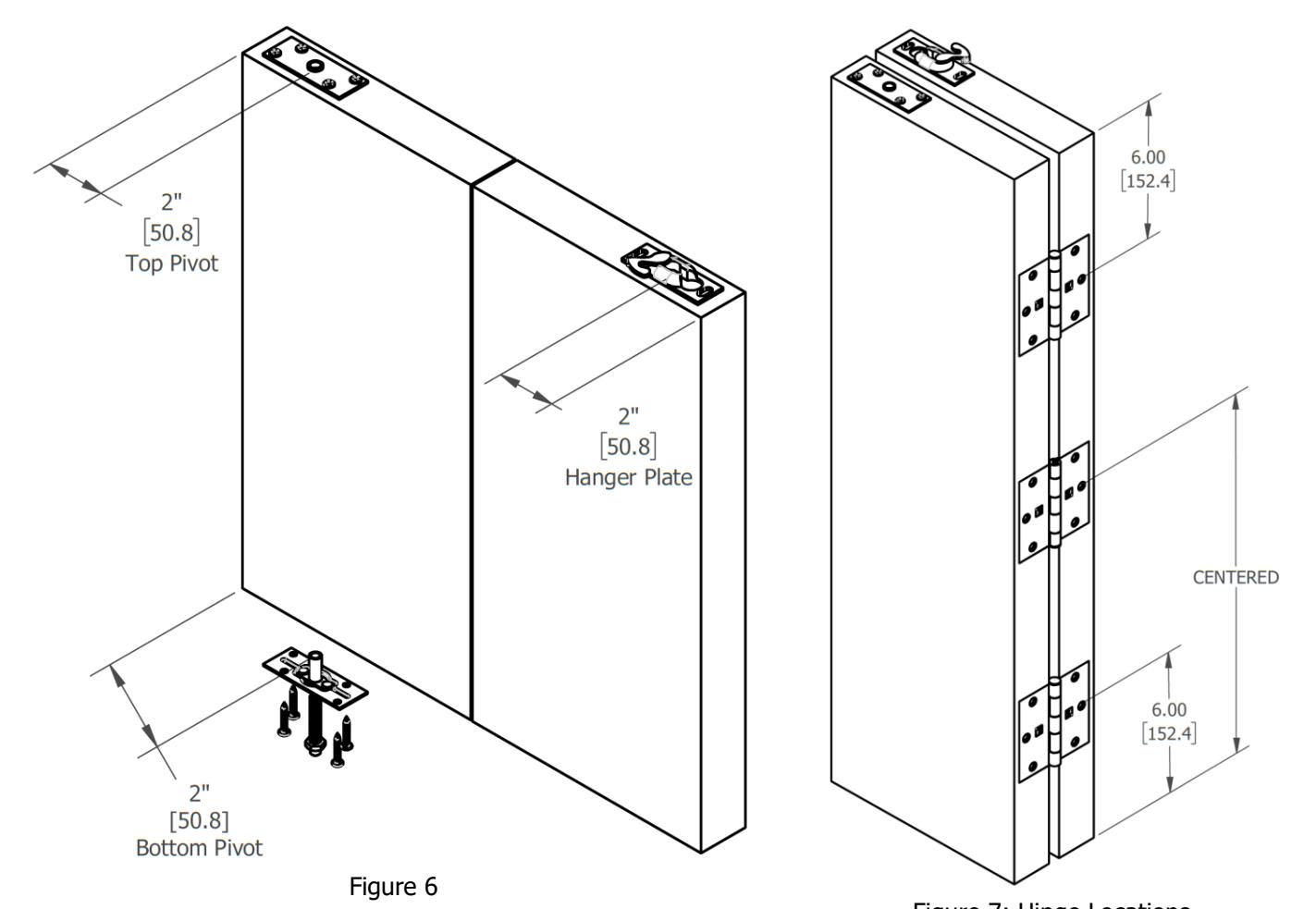
- Drill a 1-3/4" deep 3/8" diameter hole 2" from the pivot side panel edge, at the center of the top and bottom panel edge thickness
- Insert the Bottom Pivot Door Mounting Plate's protruding cylinder in the bottom hole created in the previous step
- Position the Top Pivot Door Mounting Plate 2" from the pivot side panel edge, at the center of the top panel edge thickness
- Secure both the Top and Bottom Pivot Door Mounting Plates with #8 x 1" PPHW Screws
- Position the Hanger Plate 2" from the guide side panel edge, at the center of the top panel edge thickness
- Secure the Hanger Plate with M5.5 x 32mm PPHW Screws
- Mortise the 3.5" x 3.5" Hinges to the panels Note: Ensure that the hinge barrels are on the back side of the door
- Secure the hinges with #9 x ¾" FPHW Screws

5 Hang the Doors
- Fold the doors together and engage the Top Pivot Door Mounting Plate into the Top Pivot Bracket
- Set the Bottom Pivot Adjusting Bolt into the Bottom Pivot Floor Mounting Plate Note: The Top Pivot Assembly must be loose to slide freely on the track towards the Guide Side Jamb. This will safely set the Bottom Pivot Adjusting Bolt into the Bottom Pivot Floor Mounting Plate
- Slide the 4-Wheel Roller's bolt into the Hanger Plate and close the latch
- Move the Top Pivot Assembly left and right until the pivot side panel edge is parallel to the Pivot Side Jamb
- Tighten the Top Pivot Track Bracket Bolt
- Test the bi-fold door
- Adjust the Top and Bottom Pivot Assembly left or right if necessary
- Adjust the Bottom Pivot Adjusting Bolt and 4-Wheel Roller's bolt until the bottom door edge is 3/4" from the finished floor
- Secure the Bottom Pivot Floor Mounting Plate with the remaining 2ea #8 x 1" PPHW screws Note: Make sure to stagger the screws. Either place them on the top left corner hole and bottom left corner hole or vice versa as seen in Figure 3
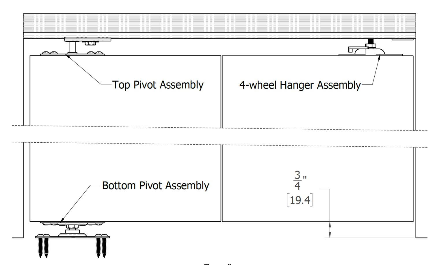
Figure 8

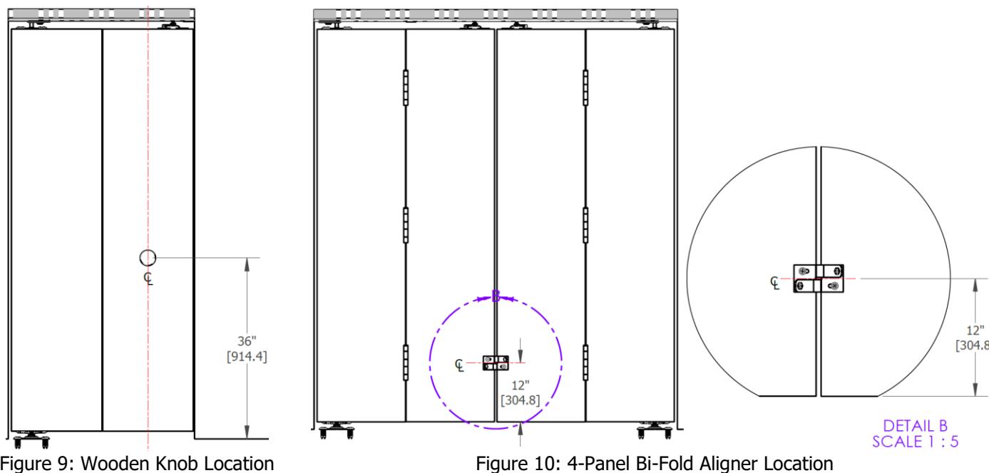
6 Install the Wooden Knob and Bi-Fold Aligner
-
Install the wooden knob at the vertical centerline of the guide side door as seen on
Figure 9
Note: Use #8 x 1-3/4" TPH Knob Screw for 1-3/8" Thick Panels
- Use #8 x 2" TPH Knob Screw for 1-3/4" Thick Panels
- Cut the #8 x 1-3/4" TPH Knob Screw to the appropriate length for 1-1/8" to 1-3/8" Thick Panels
- For 4-Panel Doors, install the Bi-Fold Aligner as seen on Figure 10
7 Attach the Bi-Fold Center Stop Bumper
• Attach the Bi-Fold Center Stop Bumper as seen on Figure 11
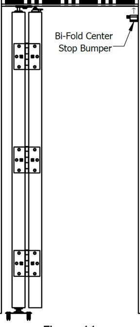
Figure 11