web_FM542_CR_ED4000_ED5000_M61_Alarm_Kit_Instr_lo_FM542
Open the original PDF document
View PDF

|
CYLINDER
LENGTH |
1-1/8" (29) | 1-1/4" (32) | 1-1/2" (38) |
|---|---|---|---|
| COLLAR | NONE | 270F15 | 654F07 |

In U.S.: Corbin Russwin, Inc. 225 Episcopal Road
Phone: 800-543-3658 Technical Product Support: Phone: 888-607-5703
Berlin, CT 06037 USA
In Canada: ASSA ABLOY Door Security Solutions Canada 160 Four Valley Drive Vaughan, Ontario, Canada L4K 4T9 Phone: 800-461-3007
FM 542 11/18
This product can expose you to lead which is known to the state of California to cause cancer and birth defects or other reproductive harm. For more information go to www.P65warnings.ca.gov.
08/2018

Corbin Russwin ASSA ABLOY
EXIT ALARM INSTRUCTIONS
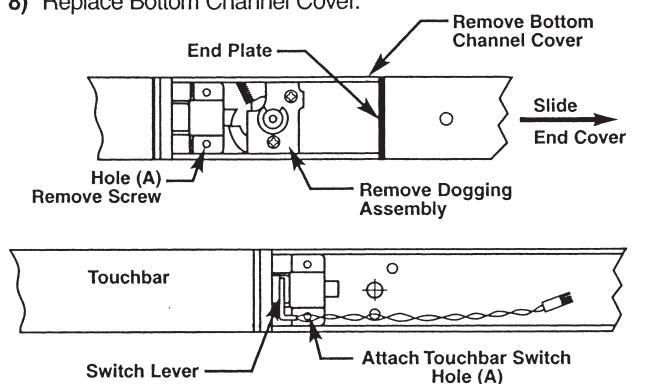
STEP 1 – Install Touchbar Switch Retrofit Applications Only - All Except SVR
- 1) Remove Device from door.
- 2) Remove End Cover and black End Plate. Discard End Plate.
- If Device has dogging, remove dogging assembly with (2) screws and discard.
- 4) Remove Bottom Channel Cover from Device.
- Locate rear touchbar mounting hole (A) as indicated below. Remove screw, if one is assembled, and install in opposite hole
- 6) Remove screw from Touchbar Switch Bracket and align screw hole over touchbar mounting hole (A). Reinstall screw from bottom of channel to secure Switch
- 7) Verify that moving the Touchbar causes the switch to trip. Adjust switch lever as required.
- 8) Replace Bottom Channel Cover.
STEP 2 – Size End Cover
- For NEW installations, follow procedures in Device installation instructions.
- 2) For RETROFIT applications, cut new Alarm End Cover to same length as old End Cover.
- Cut Alarm End Cover on end opposite Cylinder hole as shown
Note: Cover can be cut to a minimum length of 9-1/4" (235 mm), not including thickness of End Plate.

STEP 3 - Assemble Alarm End Cover
- 1) Slide Alarm Housing Assembly into Alarm End Cover, making sure tabs are engaged and LED is inserted into lens.
- Insert Cylinder, with Collar if required, into Alarm End Cover aligning cylinder grooves with locating tabs on housing assembly.
- Note: Cylinder keyway to be positioned towards Touchbar.3) Install Arming Switch Activator over Cylinder so that Activator legs are on each side of toggle switch.
- 4) Secure parts with Alarm Cylinder Nut, making sure Activator rotates freely. Check that rotating the key causes Activator to trip switch in both directions. Bend Activator legs as required.

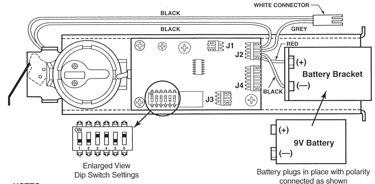
STEP 4 – Install Alarm Assembly
- 1) Install 9V Battery with correct polarity. Verify all connections and switch settings. (See Tables 1, 2 and 3 on next page).
- 2a) ALL EXCEPT SVR
Attach (2) white connectors.
2b) SVR FACTORY-WIRED ONLY
Attach (2) white connectors and (2) red connectors.
- 3) Install Alarm End Plate while sliding Alarm End Cover onto Device. Make sure wires are not pinched or cut.
- 4) Install Device on door and check alarm functions.
- 5) Install Alarm Label on Touchbar or on door above device.


ALARM FUNCTION AS SHIPPED
- 1) Upon arming, LED will flash AMBER and device will allow egress without triggering alarm for 7 seconds. Time Delay is factory preset see Table 1.
- 2) After 7 seconds, alarm will chirp one time and device will be ARMED . The LED will flash RED every 30 seconds, indicating device is ARMED .
- 3) Once device is ARMED, egress will result in an alarm sound that will stop only when device is RE-ARMED by key.
- 4) Low Battery Indicator Alarm will chirp every 10 seconds, indicating battery needs to be replaced.
NOTES:
- Alarm PC Board has Dip Switches DS-1, 2, 3, 4, and 5 factory preset per Tables 1, 2, and 3 shown below.
- Dip Switch DS-6 is for "hard wire" configurations and setting does not affect stand-alone battery operation.
| Passage Time Delay | TABLE 1 | ||
|---|---|---|---|
| DS-1 | DS-2 | Time Delay | |
| When the device is initially ARMED by key, the LED will flash AMBER and allow egress for a time defined in Table 1. | *Off | *Off | 7 Seconds |
| Off | On | 10 Seconds | |
| On | Off | 15 Seconds | |
| On | On | 20 Seconds | |
| Automatic Alarm Reset | TABLE 2 | ||
| The alarm can be set so that it will reset itself after a violation has occurred per Table 2. If the device automatically resets, the indicator light will flash GREEN every 30 seconds instead of RED to indicate a violation | DS-3 | DS-4 | Reset Time |
| Off | Off | 2 Minutes | |
| Off | On | 5 Minutes | |
| On | Off | 10 Minutes | |
| has occurred. | *On | *On | No Auto Reset |
| Armed and Violation LED Color Selection | TABLE 3 | ||
| Device is shipped standard, per Table 3, so that RED LED flashes every 30 seconds when device is ARMED , and flashes GREEN every 30 seconds under auto reset, when door has been violated. | DS-5 |
Armed
LED Color |
Armed Violation
LED Color |
| *Off | Red | Green | |
| On | Groon | Rad | |
Red
Green
* Factory Preset