
47271257
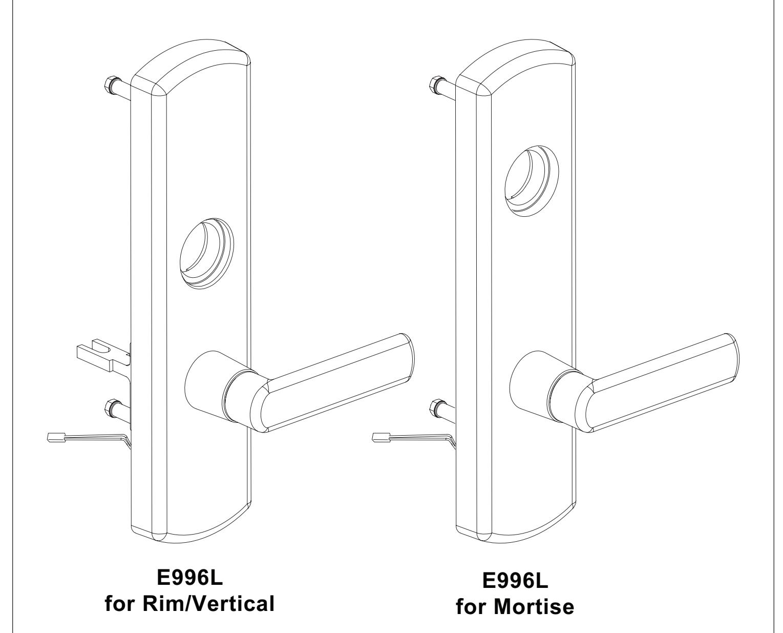
E996L Series
Electric Locking Trim Installation Instructions
! CAUTION
Product is shipped in Fail Safe (FS) configuration. Fail Safe configuration is required by code in some applications (typically fire stairwells). Consult building codes before converting to Fail Secure (FSE) configuration. See page 2 for FS/FSE function information.
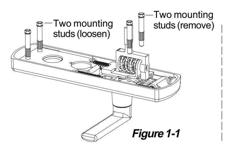
Change function (Fail Safe or Fail Secure) if necessary.
- 1.1. Using a 5/16" wrench, remove two mounting studs nearest the lever and loosen the other two mounting studs (Figure 1-1).
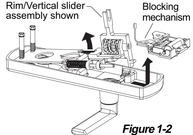
- 1.2. For change in function, lift slider assembly up at an angle and remove blocking mechanism (Figure 1-2). For upgrade kit, remove slider assembly and replace with new slider assembly (Figure 1-2).
- 1.3. Remove the two solenoid screws using 7/64" hex wrench. Flip solenoid to correct direction for FS (fail safe) or FSE (fail secure) as shown below. Route wires through opening as shown and secure solenoid with two screws (Figure 1-3). After tightened, blocking slider must move freely (Figure 1-4).
- 1.4. Route wires through bottom of bracket and into slots as shown below (Figure 1-5).
- 1.5. Reinstall blocking mechanism and place slider assembly back into place.
- 1.6. Secure four mounting studs (Figure 1-1). FS FSE (fail (fail s`afe) secure) slight vertical
Unit unlocks when

IMPORTANT Blocking slider must move freely. movement. plunger side plunger
Figure 1-4
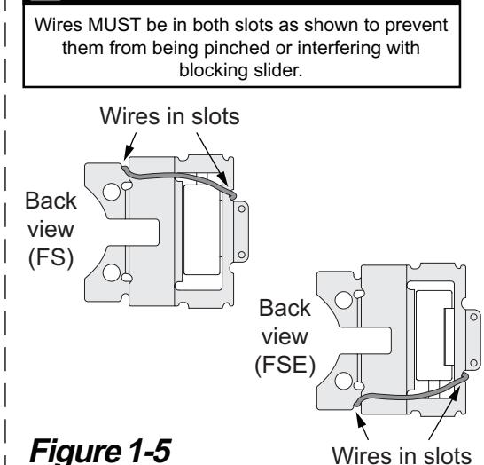
Wires in slots
IMPORTANT
2 Change lever handing of trim if necessary.
2.1. See back side of instruction sheet 921003 or 921006 "To change lever handing".
3 Install cylinder if necessary.
3.1. See front side of instruction sheet 921003 or 921006 (cylinder installation figure).
Unit locks when electric
removed
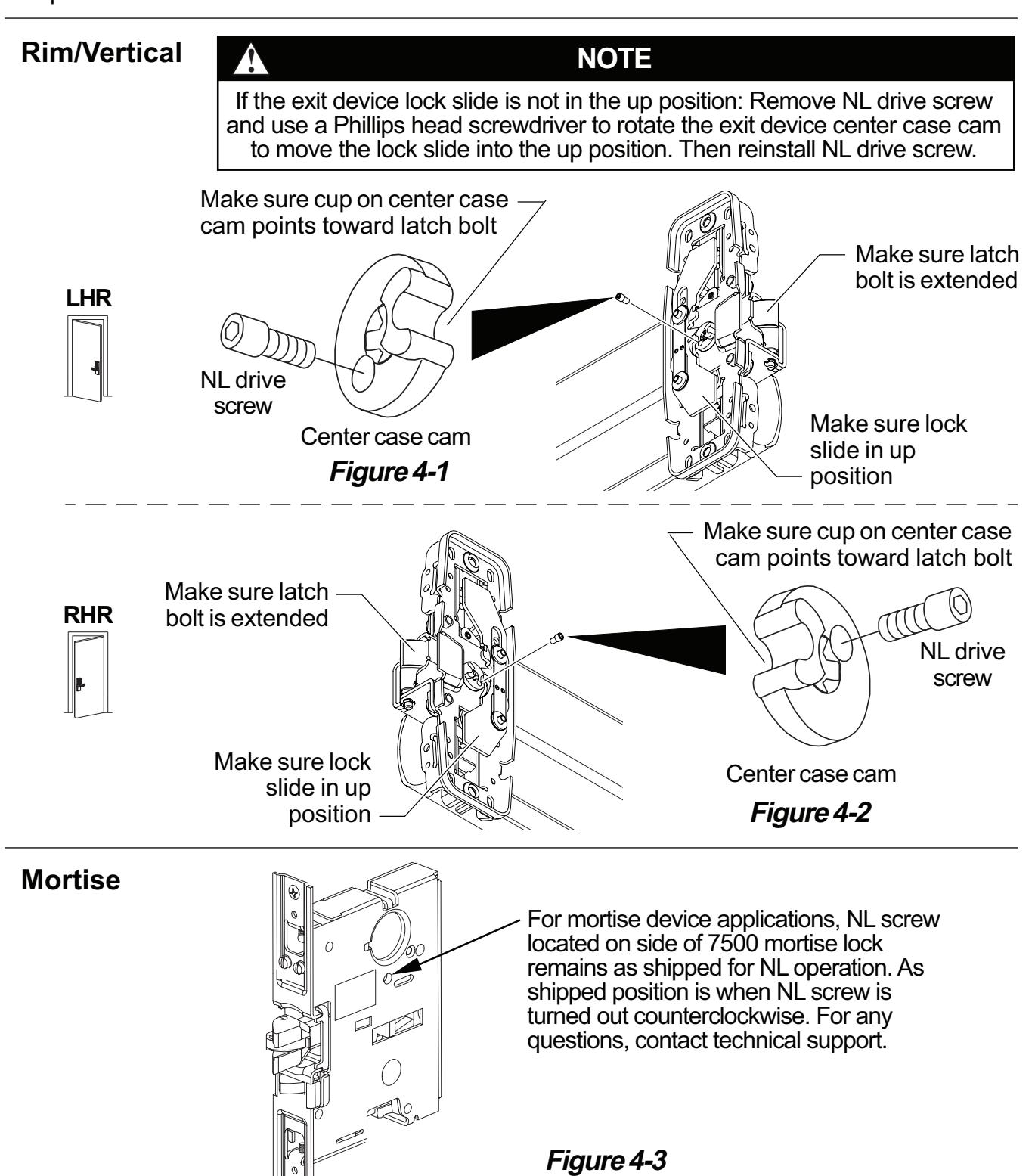
4 Check exit device NL drive screw.
For rim/vertical device applications, make sure the NL drive screw is installed in the exit device center case cam with the exit device lock slide in the up position. See figure 4-1 for LHR applications and Figure 4-2 for RHR applications. (Device is shipped from factory with NL drive screw installed.)
For mortise device applications see Figure 4-3.
Installation of the NL drive screw sets the exit device for NL (night latch) operation, which is required for use with the E996L rim/vertical trim.
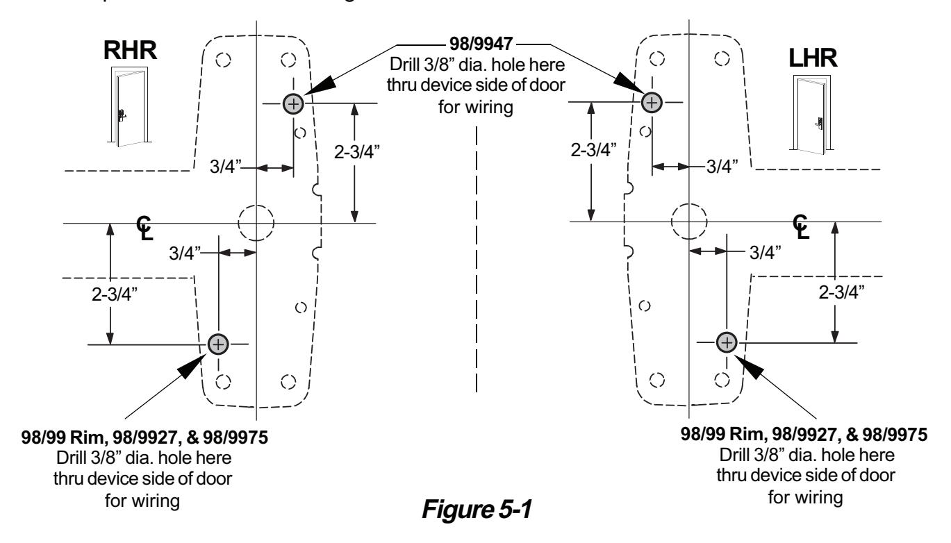
5 Prepare holes and cut-outs on door.
- 5.1. Prepare exit device side of door using instructions and template provided with exit device.
- 5.2. Prepare trim side of door using dimensions on front side of instruction sheet 921003/921006.
6 Locate wire access slots.
Note: Each center case has 4 slots that can be used for wire access. Some slots may be obstructed by optional equipment.
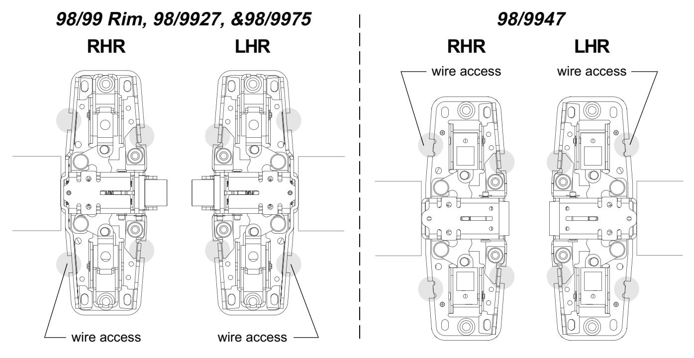
Figure 6-1
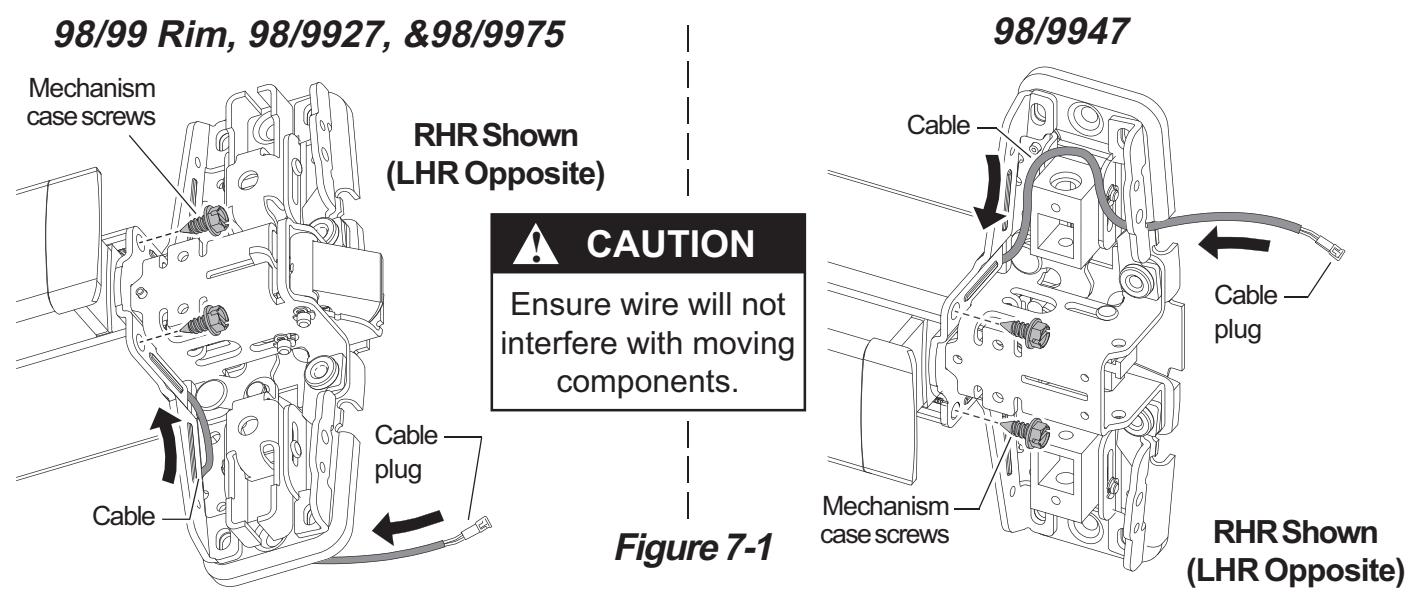
7 Route E996L cable through 98/99 series exit device.
- 7.1. Remove two mechanism case screws (Figure 7-1).
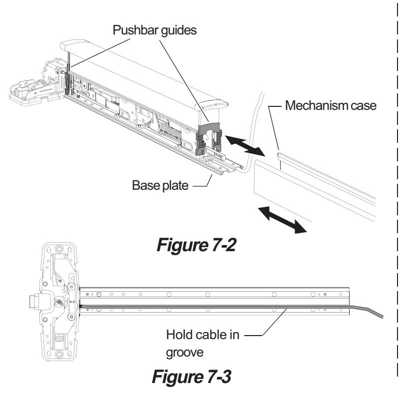
- 7.2. Slide mechanism case off baseplate assembly (Figure 7-2).
- 7.3. Route E996L cable through center case slots as shown (Figure 7-1). Cable plug should be on door side of center case as shown (Figure 7-1).
- 7.4. Place E996L cable in groove on bottom of baseplate (Figure 7-3).
- 7.5. Slide mechanism case back on device. Align two plastic pushbar guides while installing mechanism case (Figure 7-2).
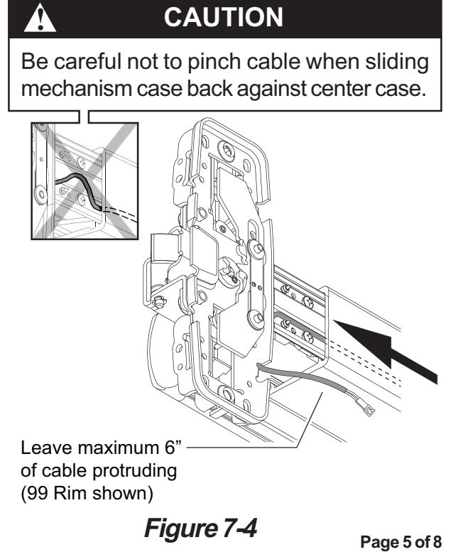
- 7.6. Slide mechanism case back against center case. Leave maximum 6" of cable protruding from center case end of device (Figure 7-4).
- 7.7. Reinstall two mechanism case screws (Figure 7-1).
8 Locate end cap bracket on door and prepare second wiring access hole.
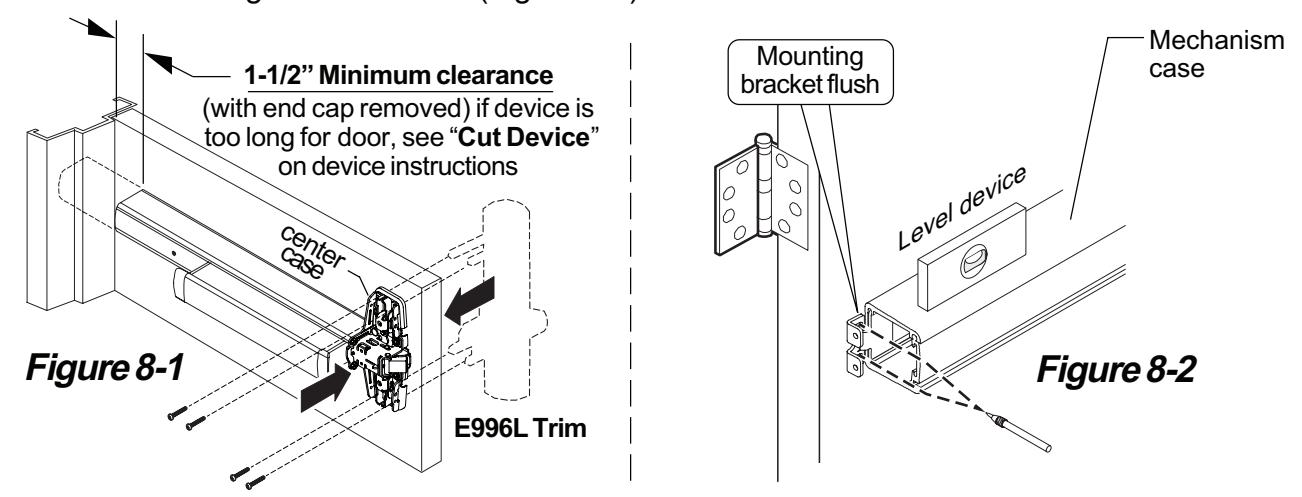
- 8.1. Temporarily attach trim and device to door with 4 screws (Figure 8-1).
- 8.2. Slide mounting bracket in end of mechanism case and level device, then mark two mounting holes on door through bracket holes (Figure 8-2).
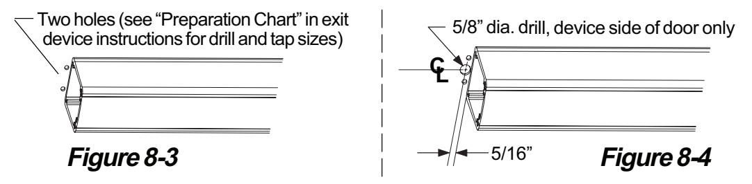
- 8.3. Mark and prepare two holes for mounting bracket screws (Figure 8-3).
- 8.4. Mark and prepare 5/8" hole for wiring access (Figure 8-4).
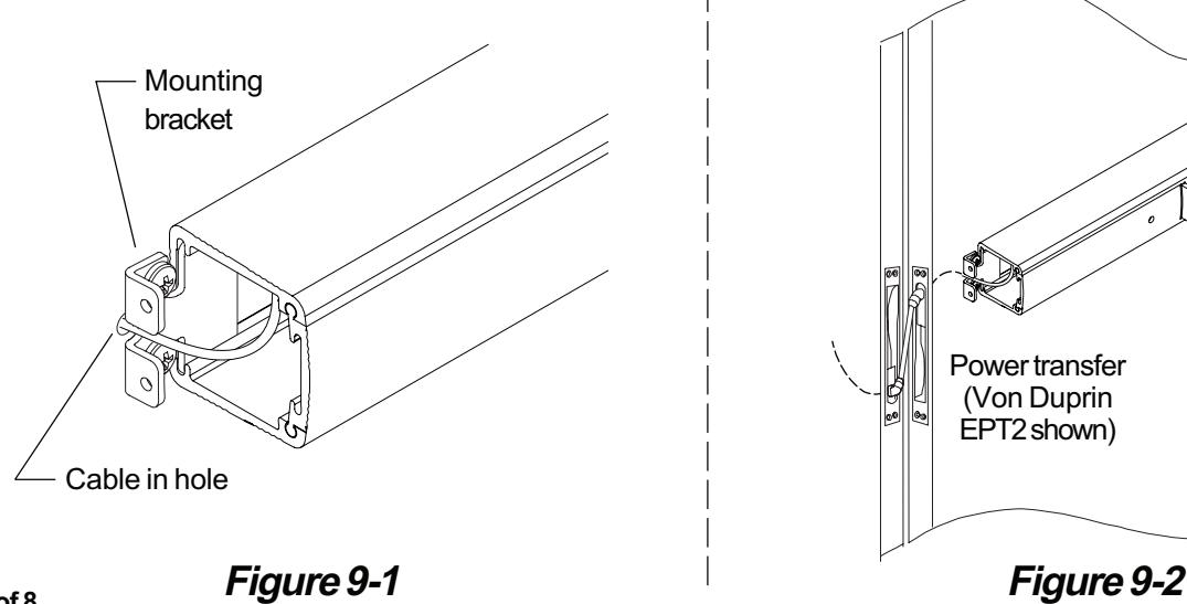
9 Install end cap bracket and route wiring through power transfer.
- 9.1. Install mounting bracket into mechanism case and install two screws loosely (Figure 9-1).
- 9.2. Slide cable into 5/8" wiring access hole under mounting bracket. (Figure 9-1).
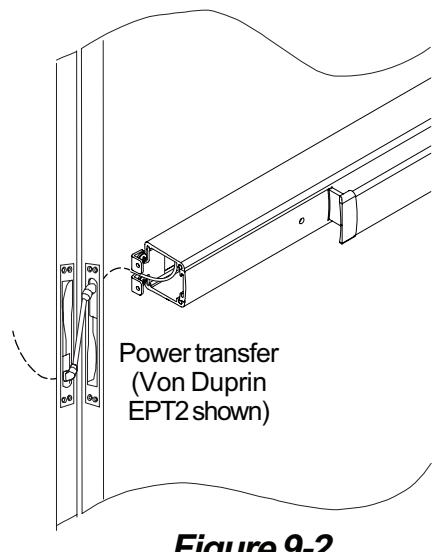
- 9.3. Route cable through door and attach wiring to power transfer. (Figure 9-2).
Note: EPT recommended for new construction; electric hinge or door loop recommended for retrofit.
Page 6 of 8
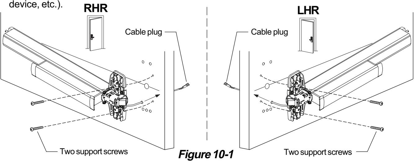
10 Attach center case to door.
- 10.1. Support hinge side of device in mounting bracket.
- 10.2. If trim has been temporarily installed, remove 4 screws in center case and remove trim.
- 10.3. Pull center case away from door and route E996L cable plug through wire access hole in door (Figure 10-1).
- 10.4. For 98/99 Rim, 98/9927, and 98/9975 secure center case to door using two support screws (Figure 10-1) or by some other temporary means (use clamps, have a helper hold the
11 For vertical or mortise devices, install vertical rods or mortise lock in door.
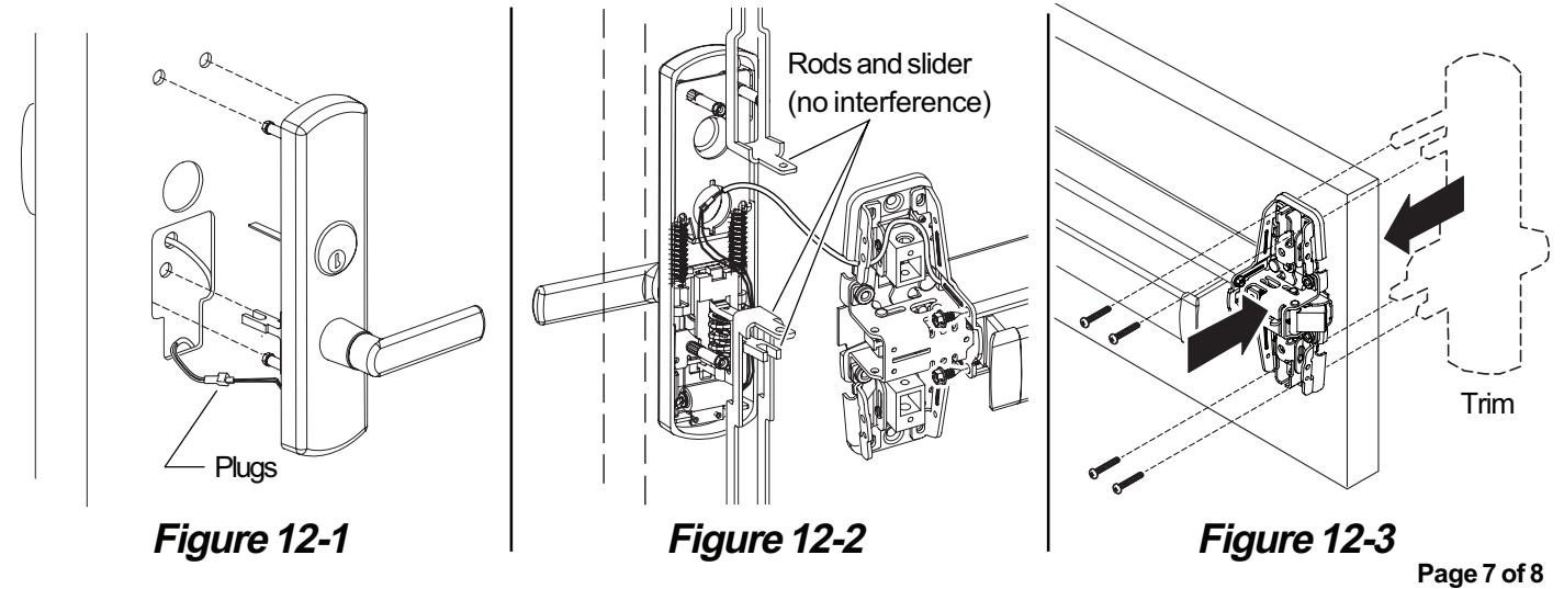
12 Install trim on door.
- 12.1. Connect trim plug and cable plug (Figure 12-1).
- 12.2. Route wires into corner of the cutout near post. Push the wires down into the door to ensure they do not contact the slider (Figure 12-1).
Note: For 98/9947 device, hold trim in door and lift center case away from the door surface while rods and trim remain in place. Route wiring as shown in Figure 12-2. Verify that the wires do not get wrapped around or pinched in rods or slider, then align center case and attach rods.
- 12.3. Attach trim to door using four screws through device center case (Figure 12-3).
- 12.4. Install center case cover (see device instructions if necessary).
13 Basic wiring information.
The two wires are non-polarized 24 VDC input. One wire connects directly to a 24 VDC power source (power supply) and the other wire connects to a control device (card reader, key pad, push button, dry contact, etc.) and then to the power supply. See diagram below.
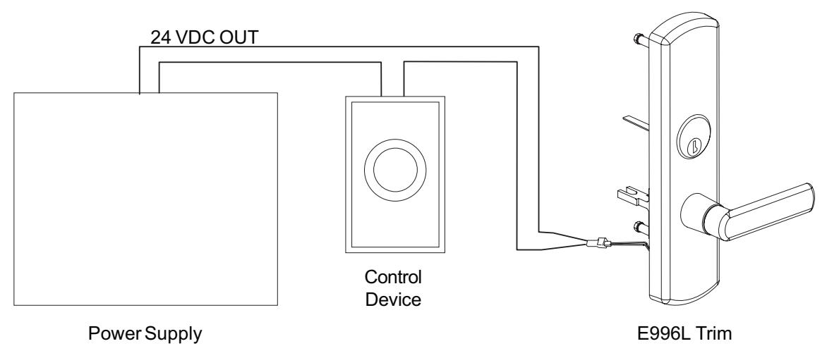
Figure 13-1
14 Test trim function.
For FS (Fail Safe) trim:
- A. With power engaged, the trim will be locked.
- B. Function the control device or disconnect main power from the power supply, the trim will unlock.
- C. When key cylinder is present on trim, with power engaged, check to ensure that the key override feature (night latch) functions properly. Inserting and turning key will temporarily unlock door while trim lever remains rigid. Door locks when key is removed.
For FSE (Fail Secure):
- A. With power engaged, the trim will be unlocked.
- B. Function the control device or disconnect main power from power supply, the trim will lock.
- C. When key cylinder is present on trim, with power disengaged, check to ensure that the key override feature (night latch) functions properly. Inserting and turning key will temporarily unlock door while trim lever remains rigid. Door locks when key is removed.