For Smartphone-friendly version, tap or click here.

47269026-00
98/9952 252L
interactives spécialisées et à des informations spécifiques aux produits.
Printed in U.S.A. 47269026 Rev. 4/19-a
1-877-671-7011 us.allegion.com
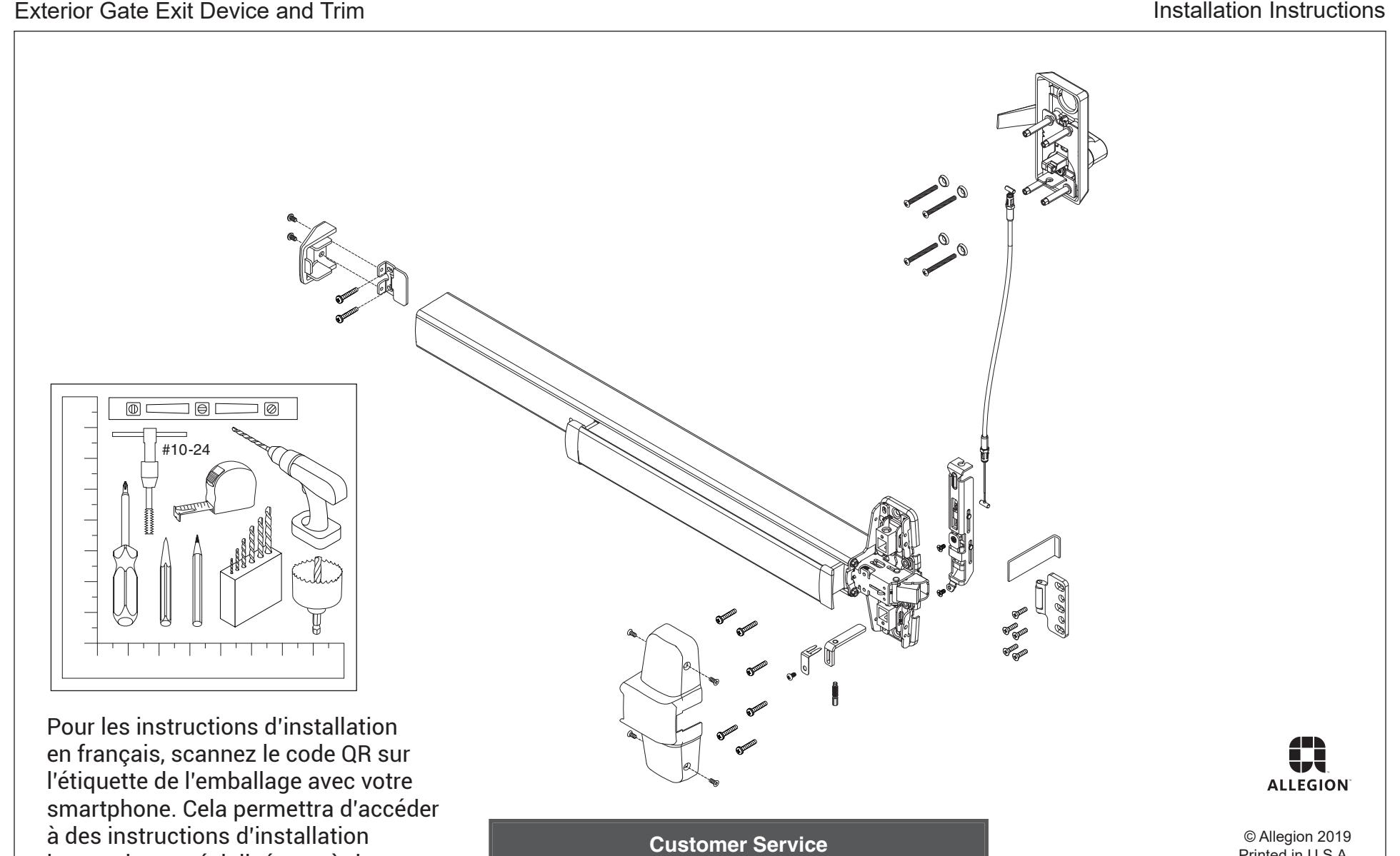
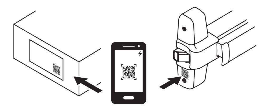
Digital Experience, Please Read!
For the best installation experience, scan the QR code on the product box label with your Smartphone.
This will give you access to specialized interactive installation instructions as well as specific product information.
Which way is your gate handed?
Right Hand Reverse (RHR)
Left Hand Reverse (LHR)
If the gate is Left Hand Reverse (LHR), the trim has to be rehanded as shown in step 2.
If RHR, go to step 3.
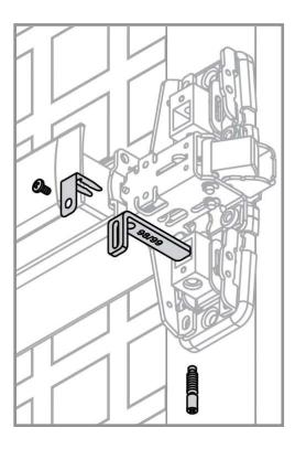
If necessary, rehand trim from RHR to LHR
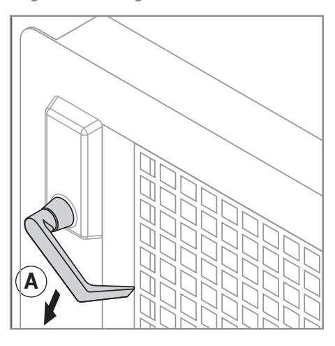
A. Remove Lower studs, cable mount, and spacer.
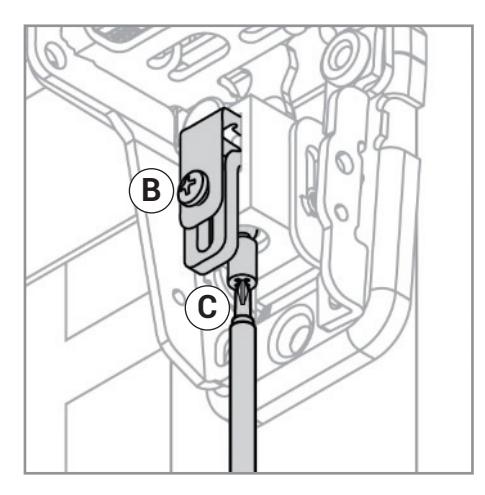
B. Remove retaining clip and set screw, cam, and shear pin.
C. Rotate lever 180 degrees to opposite side and reinstall shear pin and cam.
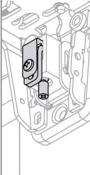
D. Make sure cam is correct orientation. LHR will show "L" on cam. You may need to push up on cable slider to insert cam.
E. Reinstall set screw and retaining clip.
F. Put cable mount and spacer together.
G. Install lower studs.
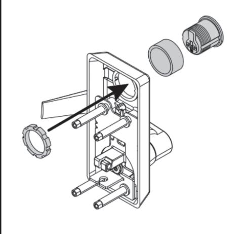
Install cylinder into trim
4
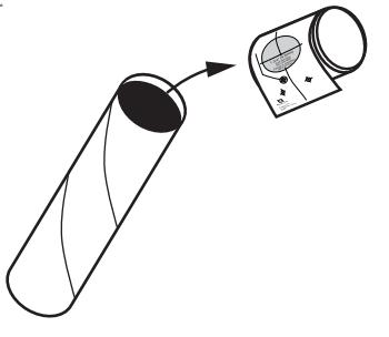
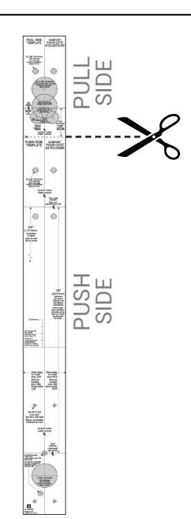
Remove templates from shipping tube and separate.
Cut on bold dotted line between Push and Pull side templates.
NOTE: If required for retrofit, additionally cut Push side template on thin dotted line (Reduce by no more than 2").
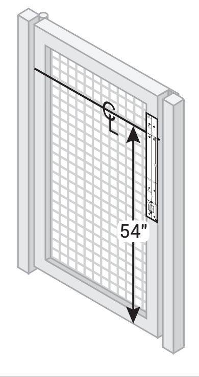
Align push side template and prepare holes and cutout
Left Hand Reverse (LHR) shown
Right Hand Reverse (RHR) opposite
- A. Mark trim centerline 54" from bottom of gate.
- B. Align template and mark holes.
- C. Prepare holes and cutout.
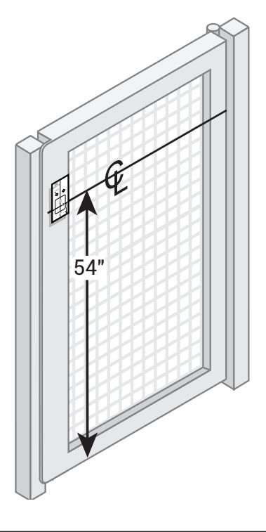
Align pull side template and prepare holes and cutout
- A. Mark trim centerline 54" from bottom of gate.
- B. Align template and mark holes. C. Prepare holes and cutout.
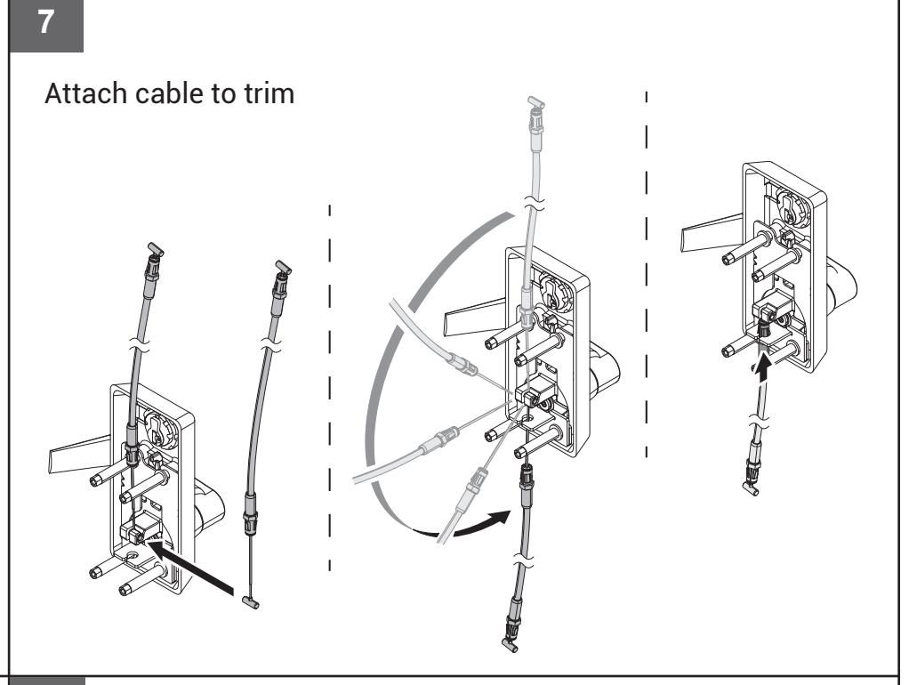
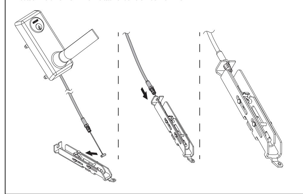
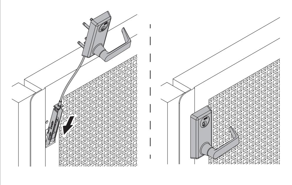
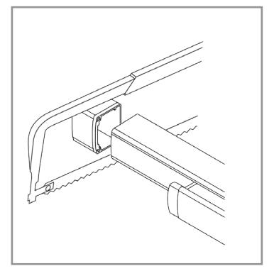
Attach other end of cable to center slide
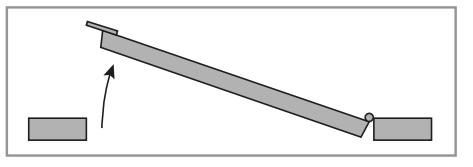
Slide trim assembly into pull side of door
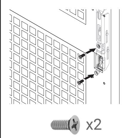
Secure center slide with 2 screws
10 11 12 13
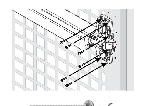
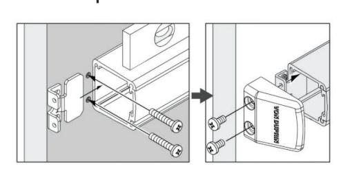
Secure trim with 4 screws and washers
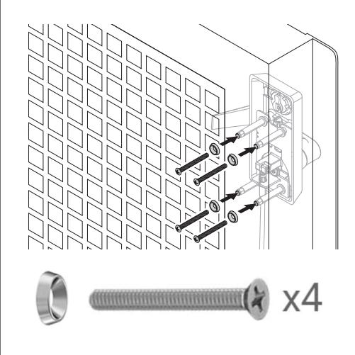
The 4 main screws are required.
The 2 security screws are optional.
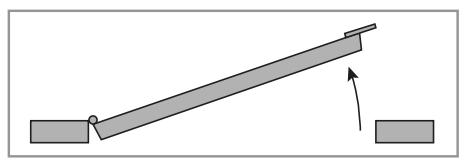
Attach center case to gate Check clearance for end cap
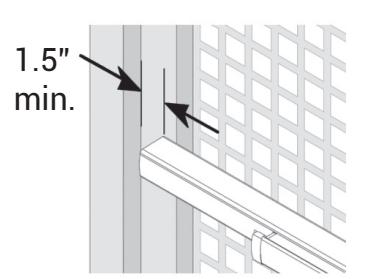
Clearance should be 1.5" minimum.
If clearance is less, you will need to cut the exit device.
14 15 16
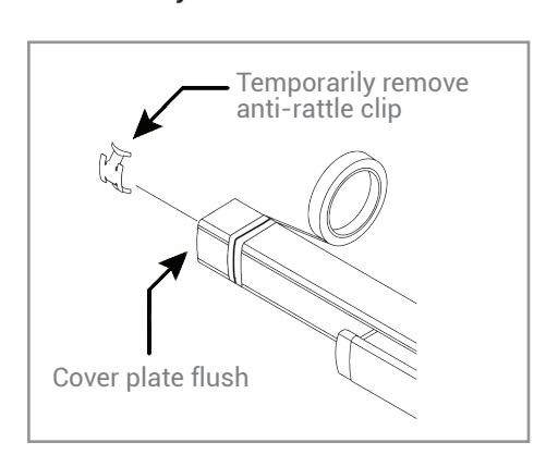
Install end cap bracket and end cap If necessary, cut the exit device Install the lift finger parts

Start screws but do not tighten.
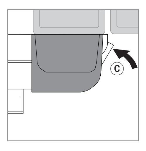
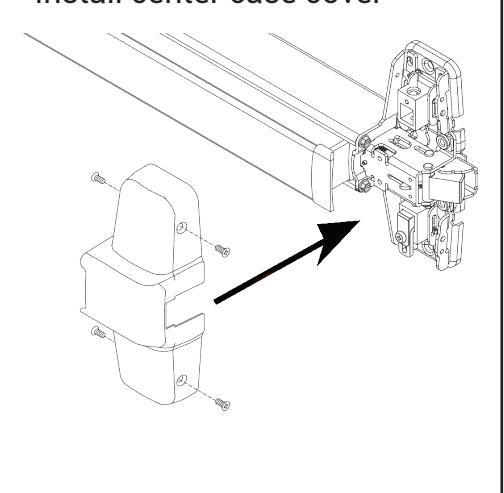
Install center case cover Adjust the lift finger
- A. Hold the trim lever down during adjustment.
- B. Loosen retaining screw.
- C. Turn the bottom adjusting screw clockwise until latchbolt retracts fully.
- D. Tighten retaining screw.
17 18
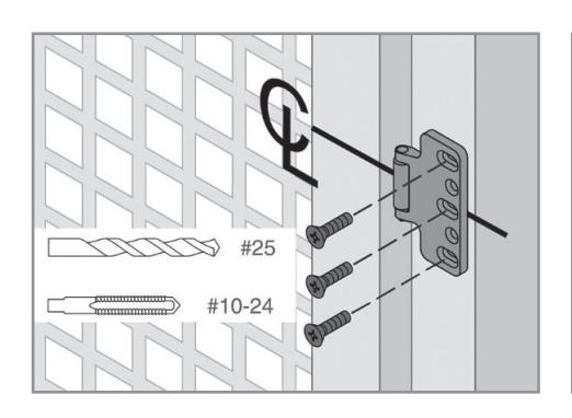
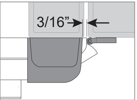
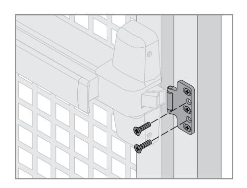
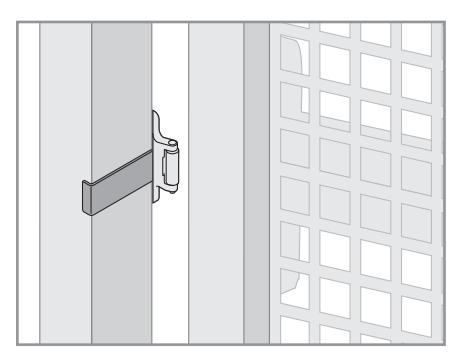
Install strike along center line on Install strike support screws post and adjust as needed
There should be a 3/16" gap between the center case cover and the strike roller.
19 20 21
Install Latchbolt rub plate
Remove adhesive and place along center line of post. The surface should be free from grease and debris to ensure a good bond.
Test door function
- A. Use key in cylinder to lock and unlock the trim, verifying locking function.
- B. Press the pushpad on the exit device and verify that the gate opens properly.
- C. With trim unlocked, pull down on the lever and verify that gate opens properly.
If the product does not function as expected, re-check the installation steps, or call Customer Service at:
1-877-671-7011
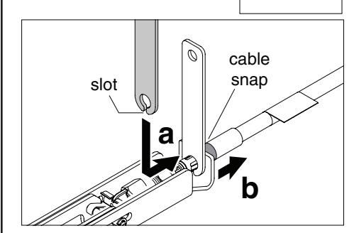
Cable Removal
for removal.
(If the cable was installed in wrong position)
A cable removal tool was included with device. Slot in tool fits over cable, holding tabs down. Pull on cable snap to loosen cable