← Von Duprin

INSTALLATION INSTRUCTIONS
The VDLBMKIT-ED is a field installable latch bolt monitor kit for the Von Duprin 33/35 & 98/99 series.
A.
VDLBMKIT-ED In clude s
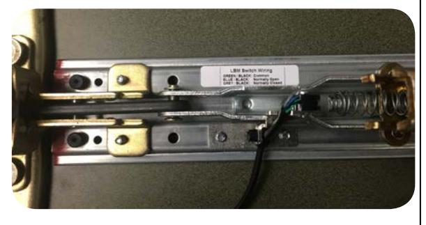
- A. LBM Label
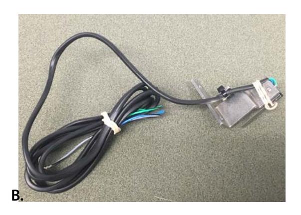
- B. LBM Switch
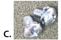
- C. 2 Phillips Screws
S p eci f ic atio n s
- Green/Black Common
- Blue/Black Normally Open (NO)
- Grey/Black Normally Closed (NC)
- .5A 24VAC/DC
To ol s Req uired
• Phillips Screw Driver

1. Remove baserail and head assembly from push pad and housing.
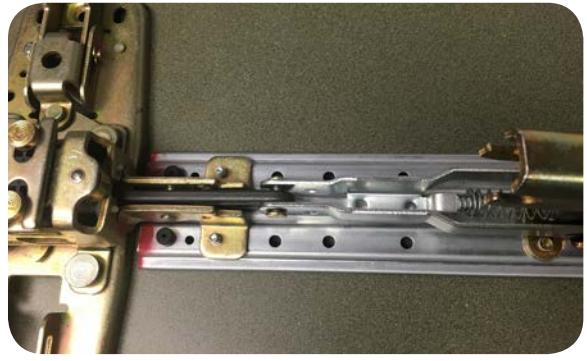
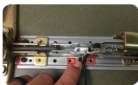
2. Position the LBM switch over the connection rod and line up with 2 screw holes in baserail.
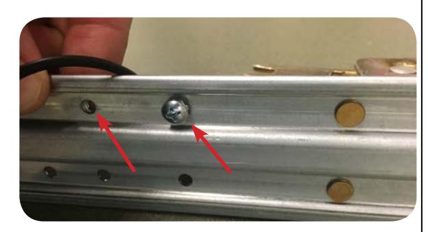
3. Flip baserail over and install 2 screws to secure bracket to baserail.
4. With switch secured remove rubber band so switch is operational.
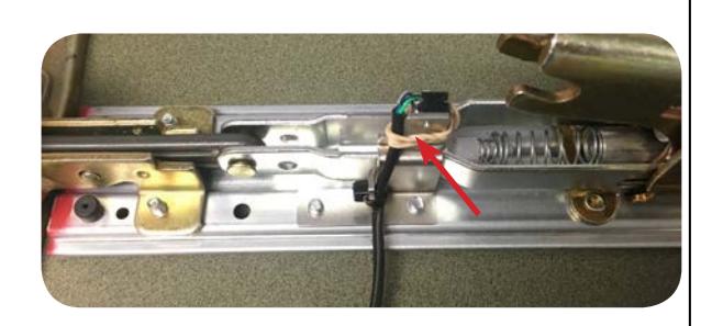
5. Place LBM sticker near switch for wire color code reference.