


801 Avenida Acaso, Camarillo, Ca. 93041 • (805) 494-0622 • Fax: (805) 494-8861 www.sdcsecurity.com • E-mail: service@sdcsecurity.com
INSTALLATION INSTRUCTIONS LR100VDK-EM ELECTRIC LATCH RETRACTION EXTERNAL MODULE VON DUPRIN MODELS: 33, 3327, 3348, 35, 3527, 3548, 98, 9827, 9847, 9857, 9875, 99, 9927, 9947, 9957 & 9975
Step 1 (for Devices without Dogging, refer to Pg. 2, Step 1A) Remove Von Duprin installed mechanical dogging assembly.
When retrofitting to existing vertical rod devices, adjustment of the rods are required for proper assembly of the LR100VDK Kit. Please see the SDC website (www.sdcsecurity.com) for installation tips and photographs of installing.
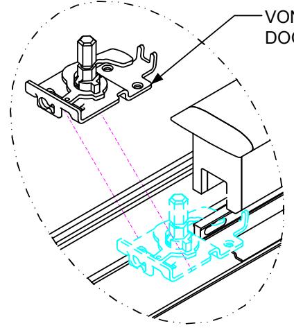
VON DUPRIN MECHANICAL DOGGING ASSEMBLY
ELECTRICAL DATA 24VDC @ 700/200mA
PATENT #8,851,530
Disconnect vertical rods from the Device head
Retrofit Installation Note:
42" or 48" exit devices that have been modified to fit a 36" or smaller opening, may not have the required space to fit the standard E. L. R. assembly. Always verify the distance from the end of the touchpad to the end rail, and if necessary, consult with the factory for appropriate selection.
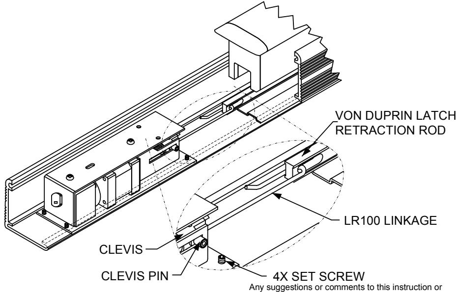
Step 2
Slide the LR100 Electric Latch Retraction assembly into device and attach the linkage to the latch retraction rod. Check for proper position and lock in place by tightening the four set screws.
INSTRUCTIONS CONTINUED ON BACK OF PAGE
NOTE: Retro-Fitting Vertical Rod Devices
Before retro-fitting an electric latch assembly into a vertical device, the following must be done to ensure proper alignment. Disconnect the vertical rods from the device head. Install the electric latch assembly as shown. Once the ELR is properly installed energize it so that the push pad is dogged down, by doing so it will allow for proper alignment for the vertical rods. Finally reconnect the vertical rods to the device and make the proper adjustments.
Step 1A INSTALLATION INSTRUCTIONS LR-1VD CONNECTING ROD FOR USE ON VON DUPRIN DEVICES WITHOUT DOGGING FEATURE
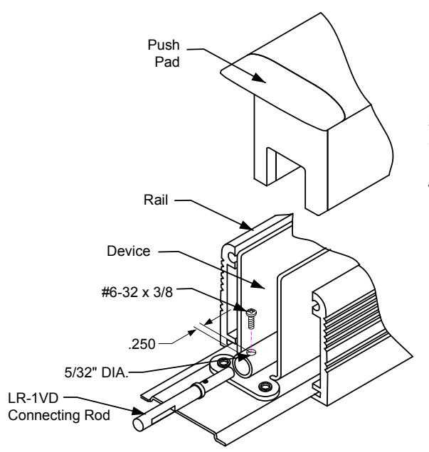
- 1. Remove the rail and push pad from the device
- 2. Drill a 5/32" (.156") diameter hole as shown in illustration.
- 3. Insert and attach the connecting rod with the #6-32 x 3/8" screw provided.
- 4. Refer to Pg. 1, Step 2 to continue.
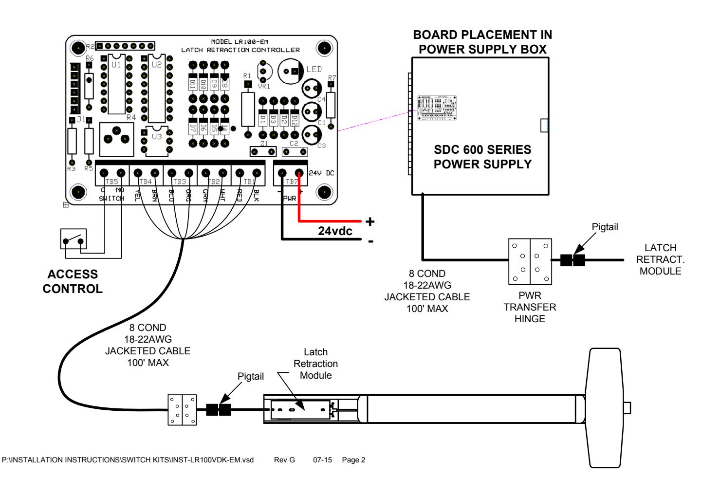
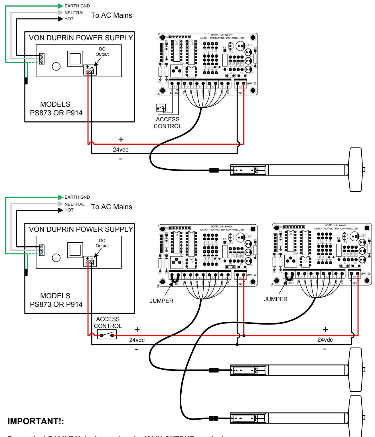
Power the LR100VDK devices using the MAIN OUTPUT terminals. The zone controller cards are not required and can damage the latch retraction units if used.
Verify that the main DC output measures at 24VDC +/- 5%.
The low current draw of each device allows both devices to operate simultaneously without the need for a sequencer.