unicon-cl-series-model-cl10-administrative-operating-instructions.pdf_638374
Open the original PDF document
View PDFUNICONTM CL SERIES
MODEL CL10
ADMINISTRATIVE OPERATING INSTRUCTIONS
Lock Modes
A lock is shipped from the factory with default lock "setup" values and a pre-set PIN for locking and unlocking the lock. This is referred to as Factory Mode .
The lock is shipped with a default factory Super Master User PIN that can be set (i.e., changed) when the lock is in Factory Mode. Once the Super Master User PIN is set, the Super Master User combination can be used to shelve the lock in the event that the Master User combination is lost. Refer to the Super Master Operations (Document # 3109.017) for more detail.
WARNING: The setting of the Super Master User PIN is optional, however, if you do not set the Super Master User PIN before setting the Master User PIN, all Super Master User capabilities will be permanently lost.
The lock is removed from Factory Mode when the Master User PIN gets changed. To remove a lock from an operational mode, one can "shelve" the lock which places it in Shelved Mode . Most lock values are returned to the factory default. Refer to the Shelve Lock operation for more detail.
Personnel Classifications
There are three different classifications of lock personnel:
- Master User The Master User performs the initial lock setup activities and can also shelve the lock. There is a maximum of one Master User per lock. The Master User combination will also lock and unlock the lock.
- Manager User A user added by the Master User. A Manager User can lock and unlock the lock. A Manager User can also retrieve reporting data from the lock if authorized to do so by the Master User.
- Lock User A user who can take temporary ownership of a locker by setting a combination to lock and unlock the lock.
There can be a maximum of 126 users who can open this lock at specific times:
- There can be a maximum of one Master User and 124 Manager Users , programmed and capable of accessing the lock at any given time.
- There can be a maximum of one Lock User (not including the Master or Manager users) programmed and capable of accessing the lock at any given time.
Access Combination Requirements
A valid access combination allows a user to lock or unlock a lock.
Master or Manager User Access Combination
An access combination for the Master User and for Manager Users is eight digits long and consists of a 3-digit User ID + a 5-digit User PIN.
Master or Manager User ID
A User ID is a three-digit number that represents a user. User ID 111 is reserved for the Master User. A maximum of 125 user IDs are available in the lock (Master User ID + 124 other user IDs.) All operations performed by users require the entry of the User's ID as the first three digits of the combination. User IDs are assigned by the Master User or by a Supervisor.
Master or Manager User PIN
A User Personal Identifier Number (PIN) is five digits. A User PIN can be defined to any combination of numbers allowed by the keypad. A PIN can also be changed at a later time.
Lock User Access Combination
The Lock User Access Combination is a 4-7 digit variable length combination that is set as each new Lock User takes ownership of the unit (locker, cabinet, etc.) that needs to be secured. The access combination can then be used to lock and unlock the lock until the current Lock User relinquishes ownership of the lock (by leaving it in an open state) and a new Lock User sets a new access combination.
Note: The Lock User does not have an actual assigned User ID like the Master User and Manager Users, but is identified as User 200 for operations recorded in the Audit trail of the lock.
Personnel Activity Chart
The following chart shows the activities that can be performed by each type of user.
| Tollowing origin original and addivided and | / | . • | \ \ \ \ \ \ \ \ \ \ \ \ \ \ \ \ \ \ \ | |
|---|---|---|---|---|
| Activity | No. | J. J. J. J. J. J. J. J. J. J. J. J. J. J | / 🔊 | |
| Set Master User PIN (p.7) | #1 | 1 | ||
| Change PIN (p.11) | #1 | 1 | 1 | N/A |
| Set Lock User Access Combination (p.12) | #1 | N/A | N/A | 1 |
| Shelve Lock - Master User (p.11) | #3 | 1 | ||
| Add Manager Users (p.10) | #4 | 1 | ||
| Delete Manager Users (p.10) | #5 | 1 | ||
| Set Lock ID (p.8) | ##1 | 1 | ||
| Toggle Sound On/Off (p.8) | ##5 | 1 | ||
| Toggle Daylight Savings Time (p.12) | ###1 | 1 | ||
| Change Reporting Capabilities (p.8) | ###2 | 1 | ||
| Lock/Unlock - Master/Mgr Combo (p.11) | 1 | 1 | N/A | |
| Lock/Unlock - Lock User Combo (p.12) | N/A | N/A | 1 | |
| Upload Data to Lock* (p.13) | #2 | 1 | ||
| Download Data from Lock* (p.15) | #2 | 1 | ✓ |
* Software Based Operations
GETTING STARTED
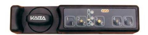
Lock Operating Conventions
- The power source for the Unicon CL Lock Series is two CR-2 Lithium 3V batteries.
- The lock is activated for operation when a keypad button is pressed. If any additional keystrokes for an operation are not completed within the allotted time of 15 seconds between keystrokes, operation abort is indicated by simultaneous green and red flashes G R with a beep 8.
- The 2 , 3 , and 4 keys on the keypad play dual roles. When pressed quickly and released, they serve as the 2, 3, and 4 keys. When pressed and held until the yellow LED displays, these keys represent the alternate symbol found on the keypad ( ¸, , and # respectively.)
The " 2 " key when pressed and held until the yellow LED displays represents the ¸ key. The ¸ key is used to clear an operation or combination entry. Two simultaneous green and red flashes are displayed after yellow flash if successful.
The " 3 " key when pressed and held until the yellow LED displays represents the (shift arrow) key. Once the yellow light appears, it will stay on until the next key is selected or until the operation times out (15 seconds).
The " 4 " key when pressed and held until the yellow LED displays represents the # key. The # key is used for keypad operations or can be used as the end delimiter for a combination (4-7 digits) when a new Lock User combination is being set. Once the yellow light appears, it will stay on until the next key is selected or until the operation times out (15 seconds).
Please note the following operational differences based on the type of bolt you have installed:
• Dead Bolt (Manual Locking) Technology:
There is a " locked " position and an " unlocked " positon for the knob on the lock that is directly related to the manual retraction or extension of the bolt. The knob must be turned in a clockwise (CW) direction to the "unlocked" position to retract the bolt and unlock the lock. Once the knob has been turned counter-clockwise (CCW) back to the "locked" position to extend the bolt and the lock has been put into a "locked" state with a combination entry, a "lock closed" audit record will be recorded indicating that the lock bolt is in the locked position and the lock is secured (locked).
• Spring Latch Bolt (Auto Locking) Technology:
There is a " locked " position and an " unlocked " positon for the knob on the lock that is directly related to the manual retraction or extension of the bolt. The knob must be turned in a clockwise (CW) direction to the "unlocked" position to retract the bolt and unlock the lock. Once the knob is released and the lock has been put into a "locked" state with a combination entry, a "lock closed" audit record will be recorded indicating that the lock bolt is in the locked position and the lock is secured (locked).
Lock Responses
- If sound is toggled "off", no beeps 8 will sound.
- After each keystroke a green flash G is displayed with a beep 8 . If the lock does not respond, the key was not pressed properly.
- After each accepted step of an operation, simultaneous green and red flashes G R display with a beep 8, prompting you to enter additional information for the next step of the operation.
- After you have completed all the steps of an operation, two simultaneous green and red flashes display with beeps G R 8 G R 8 if the operation is successful. Three red flashes R R R display with beeps 8 if the operation is unsuccessful, and you will need to re-key the operation that caused the error.
-
If a valid combination is entered to lock or unlock the lock, response will be as follows:
- · If a valid combination is entered to lock or unlock the lock, the lock will respond with one green flash G and a beep 8 to indicate that a valid combination has been entered. If unlocking the lock, one long green flash G displays with a beep 8 to indicate that the motor has fired and the lock is unlocked. If locking the lock, a long red flash R is displayed when the knob is returned to the closed position.
- · If a valid combination is entered to open the lock but the motor does not fire (motor fire error), the lock will respond with one green flash G and a beep 8 to indicate that a valid combination has been entered but will then display three red flashes R R R with simultaneous beeps 8 to indicate an error firing the motor.
- A low battery condition is indicated by ten fast yellow flashes after a valid combination has been entered. Normal operation and responses occur after that, as described above. For instructions on how to change batteries, see the following section on Lock Maintenance.
- A keystroke error or invalid combination is indicated by three red flashes R R R with simultaneous beeps 8.
- After three consecutive failed entry attempts (invalid combinations), the lock will be disabled for three minutes. Slow red flashes R display with beeps 8approx. every 2 seconds during this period. Any additional failed entry attempts (after the first three consecutive attempts) result in the lock disabling for three minutes after each failed entry attempt.
- When new batteries are installed properly , the lock will indicate this "powered" condition with simultaneous red, green, and yellow flashes with a beep 8 followed by two simultaneous red and green flashes with beeps 8.
- If new batteries are not installed properly or if batteries are almost dead , the lock may indicate this condition with six quick red flashes R R R R R R with simultaneous beeps 8. The batteries must be reinserted properly or replaced.
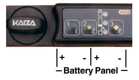
Lock Maintenance
Once you have receive the "battery Low" indication of ten fast yellow flashes after a valid combination entry, you should change the batteries in a reasonable amount of time. Remove the two screws from the battery panel and then remove the panel. Remove the CR-2 Lithium 3V batteries and replace with high quality, name brand batteries (Energizer® or Duracell®.) The negative (-) end of the battery should be inserted into the battery cavity first.
WARNING: The lock MUST NOT be sprayed with water or any cleaning liquid. Recommended cleaning is to wipe down the lock using a damp cloth or a towelette. Alcohol is an acceptable disinfectant for medical environments.
Initial Lock Operation
To test successful installation of the lock before you begin lock setup, perform the following operation.
WARNING: The container door should remain open until testing is complete.
To Lock/Unlock Using the Master/Manager Pre-Set PINs
Your lock has been shipped so that any valid Master or Manager User ID for the lock model followed by the factory pre-set PIN for that User ID will lock or unlock the lock.
Lock the Lock - Master/Manager Pre-Set
- 1. If necessary, turn the lock knob counter clockwise (CCW) to the "locked" position.
- 2. Press and hold the key until the yellow light Y displays.
- 3. Enter any valid three-digit User ID for the lock model followed by the default factory PIN for the User ID. ( For User ID 111 the default PIN is " 12345 ". For all other Users IDs the default PIN is " 55255 ". ) If the combination is entered successfully, the lock displays one green flash G with a beep 8 to indicate that a valid combination has been entered. One long green flash G displays with a beep 8 to indicate that the motor has fired and the lock is in the "locked" state. A long red flash R is displayed to indicate that the knob is in the closed position and the lock is locked.
Note: A "combination locked state" audit record is written at this point followed by a "lock close" audit record if the knob is in the "locked" position. If the knob is not fully turned CCW to the "locked" position, the long red light R will not display at the end of the operation and the "lock close" record will not be written.
Unlock the Lock - Master/Manager Pre-Set
- 1. Press and hold the key until the yellow light Y displays.
- 2. Enter any valid three-digit User ID for the lock model followed by the default factory PIN for the User ID. ( For User ID 111 the default PIN is " 12345 ". For all other Users IDs the default PIN is " 55255 ". )
If the combination is entered successfully, the lock displays one green flash G with a beep 8 to indicate that a valid combination has been entered.
One long green flash G displays with a beep 8 to indicate that the motor has fired and the lock is unlocked.
Note: A "lock open" audit record is written at this point.
3. Turn the lock knob clockwise (CW) to the "unlocked" position to open the secured unit (cabinet, cart, drawer, etc.)
Practice locking and unlocking the lock several times with the pre-set PINs before you set a new combination.
To Lock/Unlock Using the Lock User Pre-Set Combination
Your lock has been shipped so that the factory pre-set access combination for the Lock User will lock or unlock the lock.
Lock the Lock - Lock User Pre-Set
- 1. If necessary, turn the lock knob counter clockwise (CCW) to the "locked" position.
- 2. Enter the default factory access combination of 5525 for the Lock User.
- 3. Press and hold until yellow light Y displays. If the combination is entered successfully, the lock displays one green flash G with a beep 8 to indicate that a valid combination has been entered. One long green flash G displays with a beep 8 to indicate that the motor has fired and the lock is in the "locked" state. A long red flash R is displayed to indicate that the knob is in the closed position and the lock is locked.
Note: A "lock close" audit record is written at this point if the knob is in the "locked" position. If the knob is not fully turned CCW to the "locked" position, the long red light R will not display at the end of the operation and the "lock close" record will not be written.
Unlock the Lock - Lock User Pre-Set
1. Enter the default factory access combination of 5525 for the Lock User. If the combination is entered successfully, the lock displays one green flash G with a beep 8 to indicate that a valid combination has been entered. One long green flash G displays with a beep 8 to indicate that the motor has fired and the lock is in the "unlocked" state.
Note: A "lock open" audit record is written at this point.
2. Turn the lock knob clockwise (CW) to the "unlocked" position to open the secured unit (cabinet, cart, drawer, etc.)
Practice locking and unlocking the lock several times with the pre-set combination before setting a new combination. To set a new lock user combination, see the section in this manual on Lock User Operations or you can refer to the Unicon CL10 Lock User Operations (P/N # 3111.017).
Lock Setup
The lock is shipped with a default factory Super Master User PIN that can be set (i.e., changed) when the lock is in Factory Mode. Once the Super Master User PIN is set, the Super Master User combination can be used to shelve the lock in the event that the Master User combination is lost.
Warning: The setting of the Super Master User PIN is optional, however, if you do not set the Super Master User PIN before setting the Manager User PIN, all Super Master User capabilities will be permanently lost.
If you do not wish to define a Super Master User combination for your lock, proceed to the following page to complete the lock setup activities. Otherwise, refer to the Super Master Operations sheet for instruction on setting the Super Master PIN.
The following lock setup activities need to be performed by the Master User to configure the lock for operations when the lock is in Factory Mode or has been Shelved.
- 1. Set Master User PIN (p.7)
- 2. Set Lock ID for reporting purposes (p.8)
- 3. Toggle sound off (Optional p.8)
- 4. Change reporting capabilities for lock personnel (Optional p.8)
Set Master User PIN
Note: The default PIN assigned to the Master User is "12345". The Master User must change this default PIN before any lock operations can be performed.
Once you have successfully opened the lock using the Master User's factory combination, the Master User must change the default Master User PIN by completing the following steps:
1. Press # Y and then 1 . G R 8
- 2. Enter the three-digit Master User ID 111 followed by the default Master User PIN 12345 . G R 8
- 3. Enter the three-digit Master User ID 111 followed by the new Master User PIN. G R 8
- 4. Enter the three-digit Master User ID 111 followed by the new Master User PIN again for verification. G R 8 G R 8
- 5. Record the new PIN and store it in a secure place.
Note: Once the Master User PIN has been set, the factory pre-set combinations will no longer open the lock.
Set Lock ID
If you do not want to assign an ID to the lock, the default is "0000".
Note: We recommend that you set a unique Lock ID for each lock so that the lock's information can easily be identified for reporting purposes.
- 1. Press # Y , # Y and then 1 . G R 8
- 2. Enter the Master User combination. G R 8
- 3. Enter a four-digit number for the lock ID. G R 8
- 4. Enter the number again for verification. G R 8 G R 8
Toggle Sound On/Off
The Master User can toggle the sound "on" or "off". If "on", one beep sounds each time the lock LED flashes.
Note: The default value for the lock sound is "on". This toggle can be changed at any time except when the lock is in shelved mode or when the lock is disabled.
- 1. Press # Y , # Y and then 5 . G R 8
- 2. Enter the Master User combination. G R 8 G R 8
Change Reporting Capabilities
The default reporting mode of the lock enables all administrative lock personnel (Master User and Manager User) to retrieve audit records or to retrieve user information. However, the Master User can restrict these reporting capabilities.
To change the reporting capabilities of lock personnel, complete the following steps:
- 1. Press # Y , # Y , # Y and then 2 . G R 8
- 2. Enter the Master User combination. G R 8
- 3. Enter 1 to allow only the Master User and Manager Users to retrieve reporting information; or enter 2 to allow only the Master User to retrieve reporting information. G R 8
- 4. Enter the one-digit number you entered in Step 3 again for verification. G R 8 G R 8
Lock Startup Operations
With the lock set up, you are now ready for startup operations. The following operations should be performed to enable full capabilities of the lock. The instructions for performing these operations are located in the following Lock Operations section of the manual.
Master User
1. Add Manager User(s) to the lock.
Manager User(s)
1. Change default user PIN (p. 10 - Change PIN operation)
LOCK OPERATIONS
Operations found in this section are those that can be completed as needed in the course of normal lock operation after the lock has been set up.
G = Green Flash R = Red Flash Y = Yellow Flash 8 = Beep
Administrative User Operations
The following operations are those that should be completed by the Master and/or Manager Users for administrative purposes.
Add Manager User(s)
The Master User can add a Manager User to the lock
Note: A maximum of 124 Manager Users can be added to the lock.
- 1. Press # Y and then 4 . G R 8
- 2. Enter the Master User combination. G R 8
- 3. Enter the new Manager User ID. G R 8
- 4. Enter the new Manager User ID again for verification. G R 8
- 5. If additional Manager Users are to be added, repeat Steps 3-4 until all Manager Users have been added.
- 6. Enter 111 to end the operation. G R 8 G R 8
Note: The default PIN assigned to a new Manager User ID is "55255". This default PIN must be changed by the User before any lock operations can be performed. Refer to the "Change PIN" section for instructions on changing a User PIN.
Delete Manager User(s)
Note: A Manager User can only be deleted by the person who created the User (i.e., the Master User.)
- 1. Press # Y and then 5 . G R 8
- 2. Enter the Master User combination. G R 8
- 3. Enter the Manager User ID to be deleted. G R 8
- 4. Enter the Manager User ID to be deleted again for verification. G R 8
- 5. If additional Manager Users are to be deleted, repeat Steps 3-4 until all Manager Users have been deleted.
- 6. Enter 111 to end the operation. G R 8 G R 8
Change PIN
A user (Master or Manager User) PIN can be changed at any time (however, a User ID can never be changed.)
Caution: Before changing a PIN, open the container door to allow testing with the new PIN.
1. Press # Y and then 1 . G R 8
2. Enter the combination (User ID + PIN) of the user for which the PIN is to be changed. G R 8
Note: The default PIN for a Manager User is "55255". For security puposes, the Master User PIN should not ever be changed back to the default PIN of "12345".
- 3. Enter the new combination (User ID + PIN) for the user. G R 8
- 4. Enter the new combination (User ID + PIN) for the user again for verification. G R 8 G R 8
- 5. Record the new PIN and store it in a secure place.
Unlock with Master/Manager Combination
- 1. Press Y .
- 2. Enter valid Master or Manager combination. G 8 , long G 8
- 3. Turn the lock knob clockwise (CW) to the "unlocked" position and open the door.
Note: A "lock open" audit record is written at this point.
Lock with Master/Manager Combination
- 1. Close door and turn the lock knob counterclockwise (CCW) to the "locked" position.
- 2. Press Y .
- 3. Enter a valid Master or Manager combination. G 8, long G 8, long R 8
Note: A "combination locked state" audit record is written at this point followed by a "lock close" audit record if the knob is in the "locked" position. If the knob is not fully turned CCW to the "locked" position, the long red light R will not display at the end of the operation and the "lock close" record will not be written.
Shelve Lock using Master User Combination
To remove a lock from an operational mode, you can "shelve" the lock. This operation places the lock in Shelved Mode where most lock information is returned to the factory default settings. The only information retained from the operational mode is the audit information. If the Super Master is active, it is also unaffected.
- 1. Press # Y and then 3 . G R 8
- 2. Enter the Master User combination. G R 8
- 3. Enter 5 . G R 8
- 4. Enter 5 again for verification. G 8 G 8 G R 8 G R 8
The lock will now open by entering any of the default factory combinations for the lock. (For User ID 111 the default PIN is " 12345 ". For all other Users IDs the default PIN is " 55255 ". The default Lock User access combination is "5525 ". ) You should test the lock by locking and unlocking the lock with one of these combinations.
Toggle Daylight Savings Time
The date and time in the lock can only be programmed from the PC software, but this operation enables the Master User to "toggle" the Daylight Savings Time (DST) setting at the lock, moving the clock ahead one hour or back by one hour.
- 1. Press # Y , # Y , # Y and then 1 . G R 8
- 2. Enter the Master User Combination.
The clock in the lock will be set ahead one hour or back one hour depending on what the previous DST setting was.
2 long green flashes with beeps G 8 G 8 = Moved back 1 hour
4 long green flashes with beeps G 8 G 8 G 8 G 8 = Moved ahead 1 hour
Lock User Operations
The following operations are those that are available for the Lock User.
Set Lock User Access Combination and Secure Lock
- 1. Close door and turn the lock knob counterclockwise (CCW) to the "locked" position.
- 2. Enter a 4-7 digit combination.
- 3. Press # Y .
- 4. Enter the 4-7 digit combination again for verification.
- 5. Press Y . G 8, long G 8, long R 8
Note: A "combination locked state" audit record is written at this point followed by a "lock close" audit record if the knob is in the "locked" position. If the knob is not fully turned CCW to the "locked" position, the long red light R will not display at the end of the operation and the "lock close" record will not be written.
Unlock with Lock User Access Combination
- 1. Enter the 4-7 digit user combination. G 8 , long G 8
- 2. Turn the lock knob clockwise (CW) to the "unlocked" position and open the door.
Note: A "lock open" audit record is written at this point.
Relock with Lock User Access Combination
- 1. Close door and turn the lock knob counterclockwise (CCW) to the "locked" position.
- 2. Enter the 4-7 digit lock user combination.
- 3. Press Y . G 8, long G 8, long R 8
Note: A "combination locked state" audit record is written at this point followed by a "lock close" audit record if the knob is in the "locked" position. If the knob is not fully turned CCW to the "locked" position, the long red light R will not display at the end of the operation and the "lock close" record will not be written.
SOFTWARE BASED LOCK OPERATIONS
Upload Data to Lock
As an alternative to defining setup data and user data manually at the lock, certain types of data can be defined at the PC using the Unicon CL Series Software and the information can then be uploaded (transferred) to the lock via a Smart Key.
Caution: If you are using the software to program the lock, you should not also be programming the lock manually at the lock (except perhaps in case of emergency where someone needs to be immediately deleted from a lock.) If you do update the lock manually, you must then update the same information at the PC. Data synchronization issues will occur if the data at the PC and the data at the lock are not kept the same.
Program Lock
If you choose the "Program the Lock" menu option from the Unicon CL Series PC software, you can define the following data in a Unicon CL10 lock:
- Lock ID
- Sound ON/OFF
- Reporting Capabilities
- Users
- Date & Time
- Time Windows
Note: The Program Lock operation requires a teal colored (blue green) programming key fob that has been properly prepared at the PC using the Unicon CL Series Software.
To program the lock, complete the following steps:
- 1. Press # Y and then 2 . G R 8
- 2. Enter the Master User combination. Short red flashes with beeps R 8 begin to display. From the time these flashes begin, you have 20 seconds to properly insert the prepared red reporting key fob into the lock key fob reader. If you do not properly insert the key fob within the 20 second period, short red flashes followed by three red flashes display with beeps R 8 R 8 R 8 to indicate an error and you will need to re-key the operation. If the reporting key fob has not been properly initialized, three red flashes display with beeps R 8 R 8 R 8.
- 3. Ensure that the key fob remains connected to the key reader until the lock has completed downloading the reporting data. Upon completion, two simultaneous green and red flashes display with beeps G R 8 G R 8 indicating that the programming of the lock is complete.
Add/Delete Manager Users
As an alternative to manually adding and deleting Manager Users at the lock, they can be added to and deleted from the system at the PC using the Unicon CL Series Software. The user data can then be transferred to the lock via a teal colored programming key fob.
Note: The Add/Delete Manager Users operation requires a teal colored (blue green) programming key fob that has been properly prepared at the PC using the Unicon CL Series Software.
The process for adding and deleting user information is the same as that for programming the lock. (The only difference is that the teal colored programming key fob has been initialized to "add and delete users" rather than "program the lock".) To Add/Delete Users, perform Steps 1-3 in the previous "Program Lock" section.
Upload Time
The current time can be retrieved from the PC using the Unicon CL Series Software and then uploaded to the lock via a programming key fob.
Note: The Upload Access Schedules operation requires a teal colored (blue green) programming key fob that has been properly prepared at the PC using the Unicon CL Series Software.
The process for uploading time to the lock is the same as that for programming the lock. (The only difference is that the teal colored programming key has been initialized to "upload the time" rather than "program the lock".) To Upload Time, perform Steps 1-3 in the previous "Program Lock" section.
Download Data from Lock
There are two types of data that can be "downloaded" (retrieved) from the Unicon CL10 locks.
Note: Data cannot be retrieved from the lock when in Shelved Mode.
Retrieve Audit Records
The lock's audit feature will track the following types of lock transactions in sequential order of occurrence:
- lock date/time set
- users added/deleted
- PIN activated/changed
- lock opened
- lock closed
- combination locked state
- wrong try penalty
- lock shelved
- audit report retrieved
- user table report retrieved
Each audit record will include a description of the event, the user who initiated the activity (if applicable) and the date and time stamp. The number of audit records stored by the lock is 400. If you have purchased the Unicon CL Series Software, the audit trail data stored in the lock can be downloaded from the lock and taken to the PC for reporting.
Note: The retrieve audit records operation requires a red reporting key fob that has been initialized using the PC software to retrieve audit records. When an audit is retrieved, it will overwrite any previously existing audit data that is in the key fob.
- 1. Press # Y and then 2 . G R 8
- 2. Enter the combination. Short red flashes with beeps R 8 begin to display. From the time these flashes begin, you have 20 seconds to properly insert the prepared red reporting key fob into the lock key fob reader. If you do not properly insert the key fob within the 20 second period, short red flashes followed by three red flashes display with beeps R 8 R 8 R 8 to indicate an error and you will need to re-key the operation. If the reporting key fob has not been properly initialized, three red flashes display with beeps R 8 R 8 R 8.
- 3. Ensure that the key fob remains connected to the key reader until the lock has completed downloading the reporting data. Upon completion, two simultaneous green and red flashes display with beeps G R 8 G R 8 indicating that the audit data download is complete.
4. Return the key fob to the Unicon CL Series Software PC to be read. Refer to the software documentation for instructions on reading the reporting key.
Retrieve User Table
The lock's User information reporting feature will allow retrieval of status information for all administrative users in the lock.
Note: The Retrieve User information operation requires a red reporting key fob that has been initialized using the PC software to retrieve User information. When a user table is retrieved, it will overwrite any previously existing user data that is in the key fob.
The process for retrieving User Table information is the same as that for retrieving audit information (The only difference is that the red reporting key fob has been initialized to retrieve User Table information rather than Audit information). To retrieve User Table information, perform Steps 1-4 in the previous "Retrieve Audit Records" section.
Notice: Information in this document is subject to change without notice. Kaba Mas shall not be liable for technical or editorial errors or omissions contained herein; nor for incidental or consequential damages resulting from the furnishing, performance or use of this material.
© 2007 Kaba Mas Corporation. All rights reserved.
PowerStar Technology, Auditcon, and Smart Key are registered trademarks of Kaba Mas Corporation in the United States and/or other countries.
This product is covered by one or more of the following U.S. patents:
4,803,860 5,170,431 5,265,452 5,271,253 5,410,301 5,451,934 5,488,358 5,488,660 5,493,279 5,511,401 5,590,917 5,592,838 5,709,114 5,774,058 5,774,059 5,870,914 5,873,276 5,881,589 5,893,283 5,896,026 D366,822 D388,308 D388,309
Kaba Mas Corporation 749 W. Short Street, Lexington, KY 40508 USA Phone: (859) 253-4744 FAX: (859) 255-2655 Technical Support: (800) 950-4744 www.kaba-mas.com