old mlrk1-mrk8
Open the original PDF document
View PDF


MLRK1-MRK/DH
INSERT INSTRUCTIONS
The Command Access MLRK1-MRK is a field installable motorized latch-retraction kit for:
- MLRK1-MRK Marks M9900 & M8800 series devices
- MLRK1-DH Design Hardware 1000 series device
B.

C.
D.
E.

F.

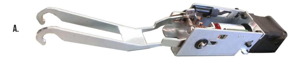
- KIT INCLUDES 1- 60280 Motor Mount w/ MM4T series module
- 2- 40706 Phillips head screws
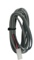
- 1- 50030 8' Lead w/ VD Connector
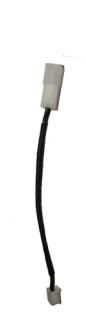
- 1- 50944 MM4T Socket Lead
- 1- 40707 Thread locking Flat tip Set Screw 8/32"
- 1- 40114 Dogging Hole Cap
TOOLS REQUIRED · Cordless Drill
- (M8800) 8/32 Tap
- (M8800) 2mm Hex Wrench
SPECIFICATIONS
- INPUT VOLTAGE: 24VDC +/- 10%
- WIRE GAUGE: MINIMUM 18 GAUGE
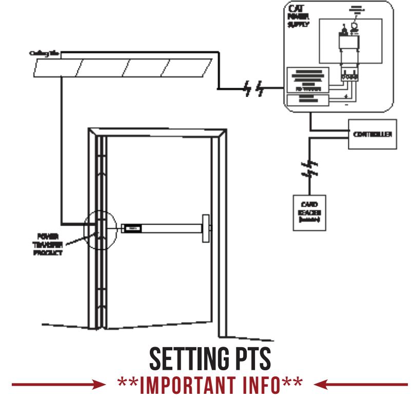
- DIRECT WIRE RUN NO RELAYS OR ACCESS CONTROL UNITS IN-BETWEEN POWER SUPPLY & MODULE
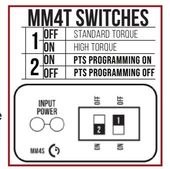
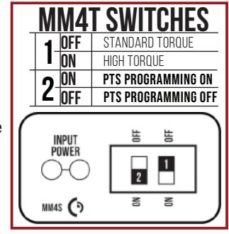
STANDARD TORQUE MODE
AVERAGE LATCH RETRACTION CURRENT: 900 MA AVERAGE HOLDING CURRENT: 215 MA
HIGH TORQUE MODE
AVERAGE LATCH RETRACTION CURRENT: 2 AMP AVERAGE HOLDING CURRENT: 250 MA
RECOMMENDED POWER SUPPLIES:
ALL COMMAND ACCESS EXIT DEVICES & FIELD INSTALLABLE KITS HAVE BEEN THOROUGHLY CYCLE TESTED WITH COMMAND ACCESS POWER SUPPLIES AT OUR FACTORY. IF YOU PLAN ON LISING A NON-COMMAND POWER SLIPPLY IT MUST BE A FILTERED & REGUL ATED LINEAR POWER SLIPPLY
TECHNICAL INFORMATION

MAKE SURE TO SET PTS BEFORE FINISHING INSTALLATION
- STEP 1 - Select your preferred torque mode (ships in standard torque). Press the device push pad to the desired setting. (We recommend to fully depress and release 5%, giving the device room for changing door conditions.)
- STEP 2 While depressing the push pad, apply power. (i.e. presenting the credential to the reader).
- STEP 3 Continue to keep the pad depressed, the device will beep 6 times. After the beeps have stopped, release the pad and the adjustment is now complete. If not to your liking repeat the 3 steps.
TROUBLESHOOTING & DIAGNOSTICS
| BEEPS | EXPLANATION | SOLUTION |
|---|---|---|
| 2 Beeps | Over Voltage | > 30V unit will shut down. Check voltage & adjust to 24 V. |
| 3 Beeps | Under Voltage | < 20V unit will shut down. Check voltage & adjust to 24 V. |
| 4 Beeps | Failed Sensor | Verify all 3 sensor wires are installed correctly. Replace sensor if problem persists by contacting office. |
| 5 Beeps | Retraction or dogging failure | After 1st fail: 5 beeps then immediately attempts to retract again. After 2nd fail: 5 beeps with pause in-between for 30 seconds then device attempts to retract again. After 3rd fail: 5 beeps every 7 minutes, device will not attempt to retract. To Reset: Depress bar for 5 seconds at any time. |
| 6 Beeps | PUSH TO SET | Device is recording it's new position and power mode after the 6th beep. |

*FOR MM4T *Latch bolt adjustment- If the latch bolt is not retracting far enough, turn the dial clockwise with a small flat blade screw driver. If the latch bolt is retracting too far causing the device to chatter and drop-out, turn the dial counter-clockwise until the chatter and drop-outs stop and the desired location is achieved.
I n s ta l l at i o n I n s t r u c t i o n s

M9900 O n ly - Fo r M 8 8 0 0 s k i p t o p a g e 7
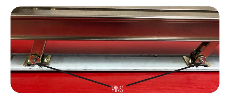
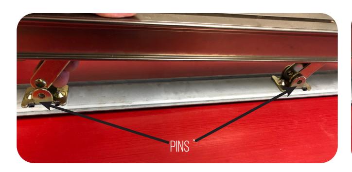
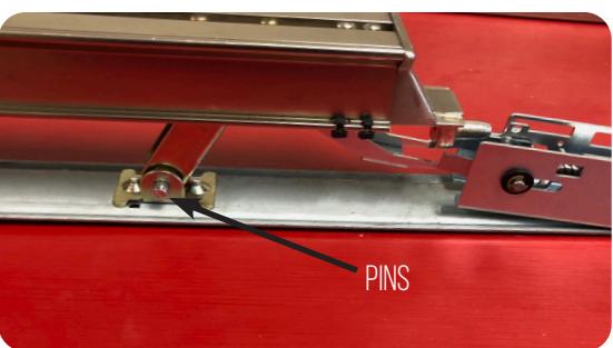
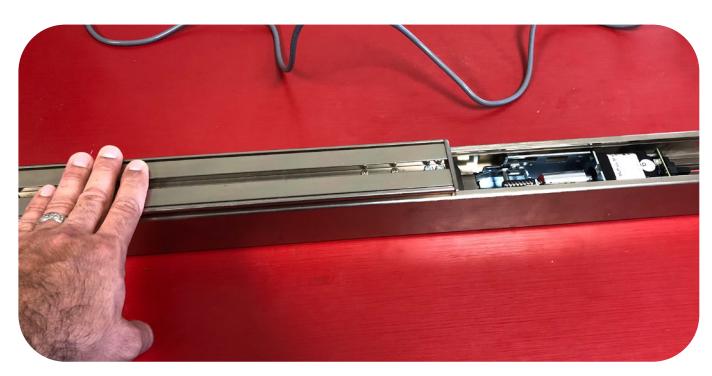
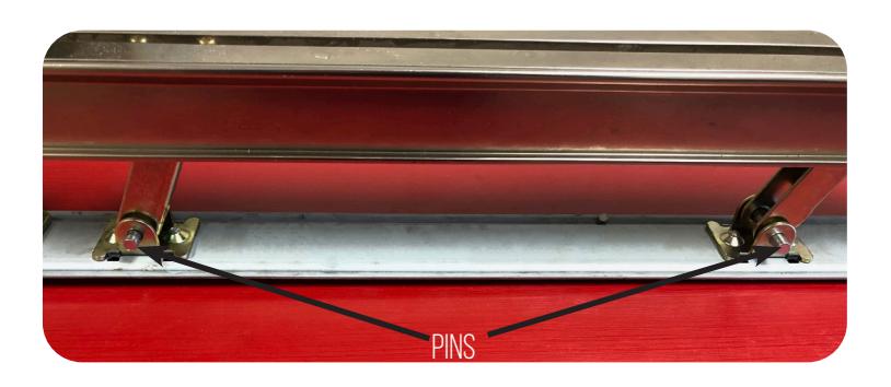
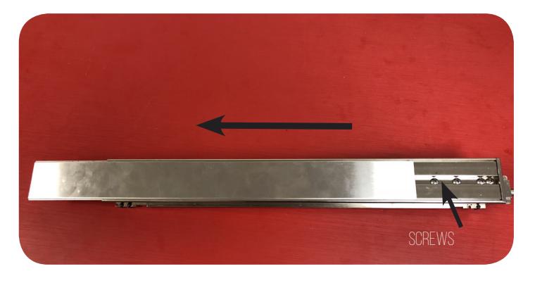
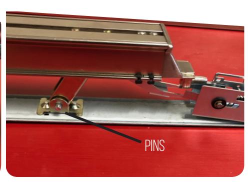
Remove head cover & Slide off housing, exposing the baserail. 1. Remove (2) Pins securing push pad to baserail. 2.
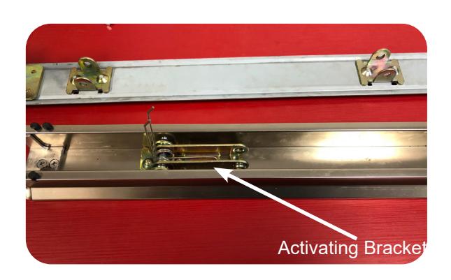
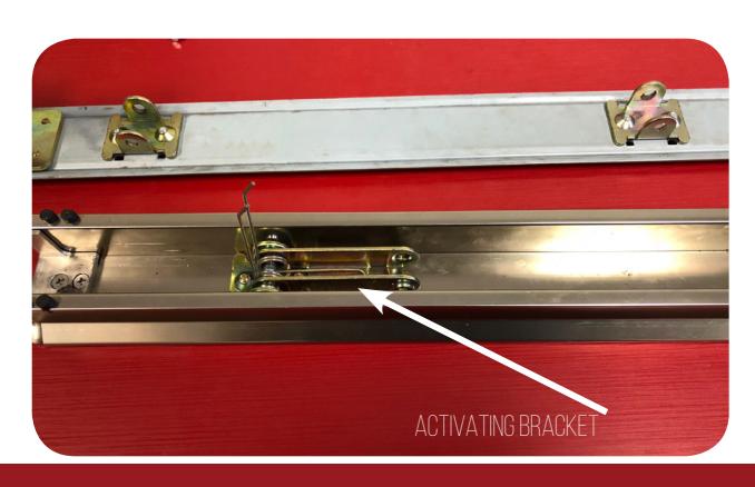
Flip over push pad, exposing activating brackets. 3. Pull activating bracket over onto spring and hold in place. 4.
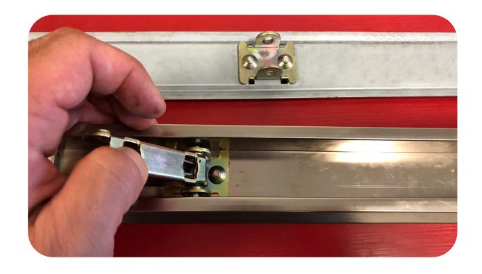
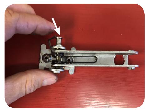
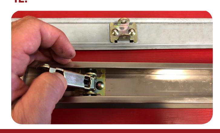
5. Holding activating bracket in place, grab motor kit & hook onto the pin on the outside of the activating bracket. Next, rotate motor kit 180 degrees to the back of the push pad.
CONTINUED

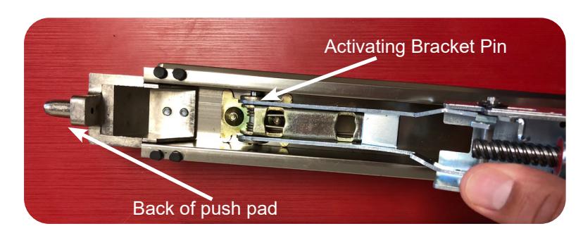
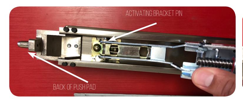
6. Flip pushpad over with kit hooked in & Reinstall (2) pins to secure push pad to baserail.
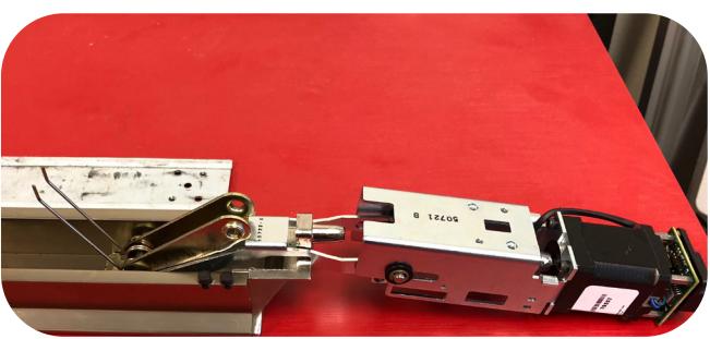
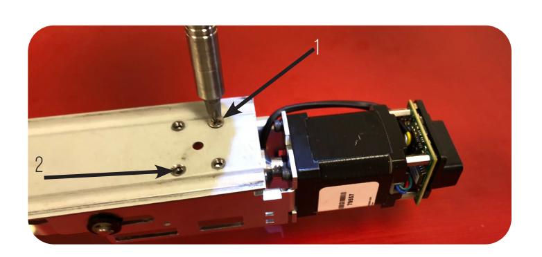
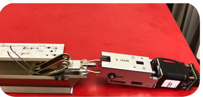
Flip baserail & push pad over to secure motor mount with (2) screws provided. 7. 8.
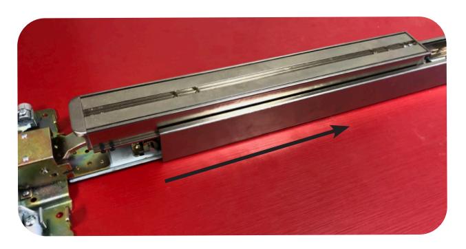
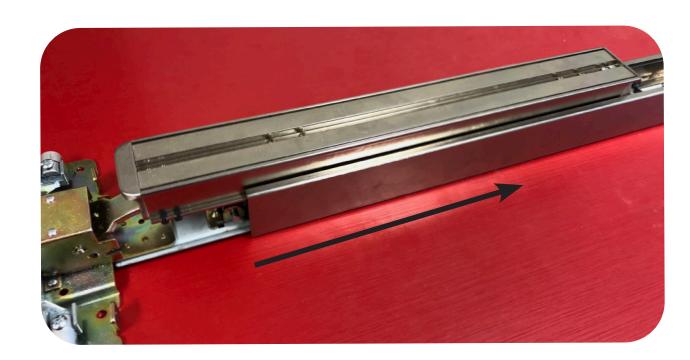
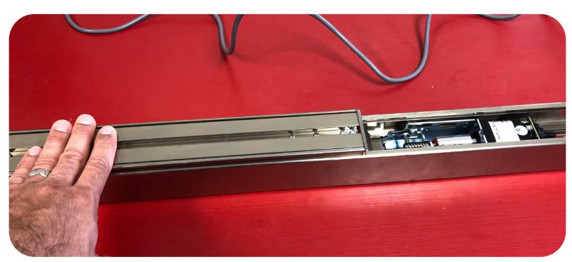
Slide baserail into housing making sure the baserail slides into the correct channel.
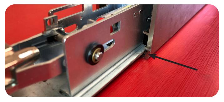
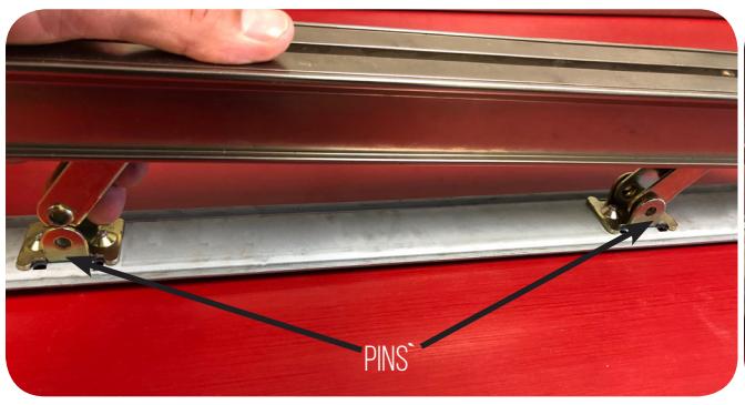
9. Make sure the (2) pins securing the push pad are centered or they will get caught on the housing.
Next, plug into power supply and test device. Once power is achieved, 10. follow steps for set the push to set (PTS) found on page 2.
CONTINUED

M8800 Installation Only
Remove head cover & Slide off housing exposing the baserail. 1. Remove (2) Pins securing push pad to baserail. 2.
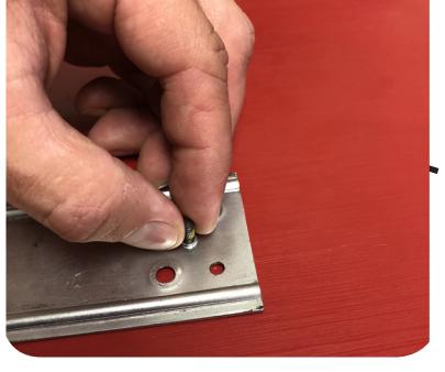
Using 8/32" tap, tap center hole on baserail in-between 4 holes. 3. 4.
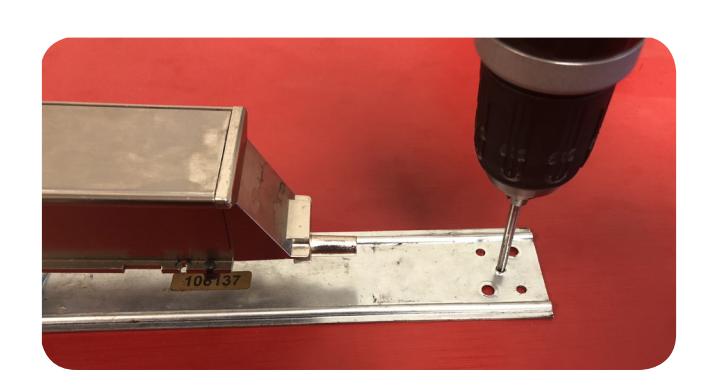
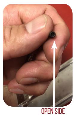
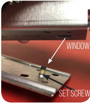
Install thread locking flat tip set screw into center hole by hand. OPEN SIDE facing down.
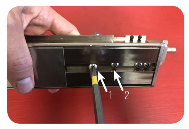
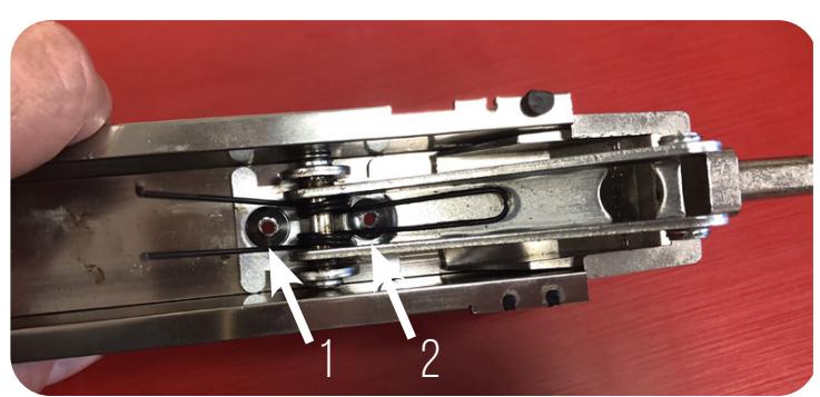
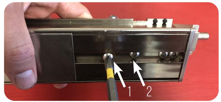
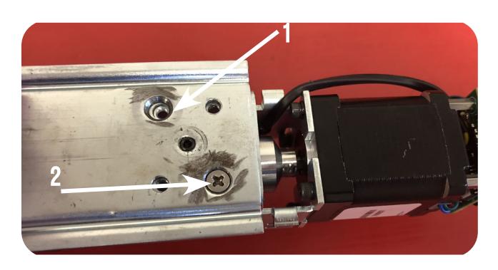
5. Flip the push pad over & remove both screws securing the FRONT push pad end cap.
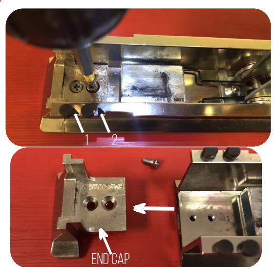

6. SLIDE PUSH PAD COVER OFF JUST ENOUGH TO REVEAL BACK (4) SCREWS ON PUSH PAD.
7. REMOVE (2) SCREWS ON THE LEFT TO REMOVE BACK ACTIVATING BRACKET.
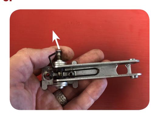
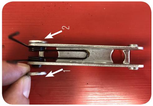
REMOVE PIN FROM ACTIVATING BRACKET THEN REMOVE THE (2) SPACERS ON EACH SIDE & DISCARD. NEXT, RE-INSERT PIN INTO ACTIVATING BRACKET.
9. PLACE BACK ACTIVATING BRACKET BACK INTO THE PUSH PAD & LINE UP WITH EXISTING SCREW HOLES.
(2) screws on the left to secure back activating bracket to push pad.
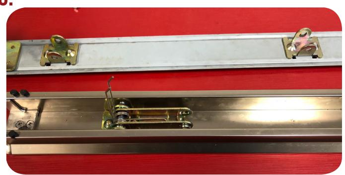
11. FLIP OVER PUSH PAD EXPOSING ACTIVATING BRACKETS.
12. PULL BACK ACTIVATING BRACKET OVER ON TO SPRING AND HOLD IN PLACE.

13. HOLDING ACTIVATING BRACKET IN PLACE, GRAB MOTOR KIT & HOOK ONTO THE PIN ON THE OUTSIDE OF THE ACTIVATING BRACKET. NEXT, ROTATE MOTOR KIT 180 DEGREES TO THE BACK OF THE PUSH PAD.
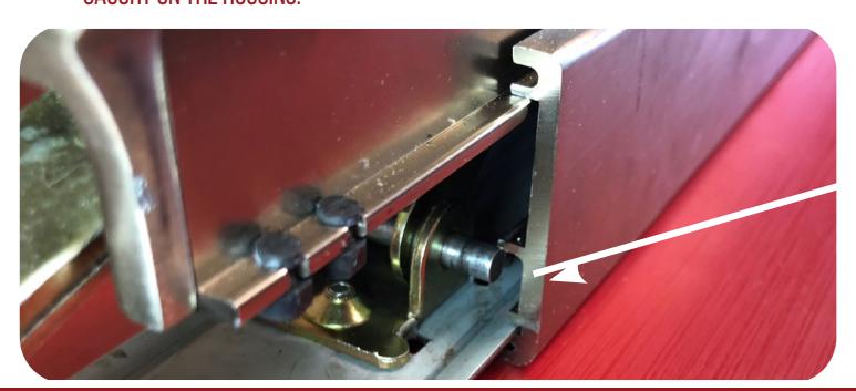
14. FLIP PUSH PAD OVER WITH KIT HOOKED IN & RE-INSTALL (2) PINS TO SECURE PUSH PAD TO BASERAIL. MAKE SURE OPENING ON THE BOTTOM OF THE MOTOR BRACKET LINES UP WITH SET SCREW IN BASERAIL.
17. MAKE SURE THE (2) PINS SECURING PUSH PAD ARE CENTERED OR THEY WILL GET CAUGHT ON THE HOUSING.
baserail into housing making sure the baserail slides into the correct channel.
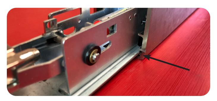
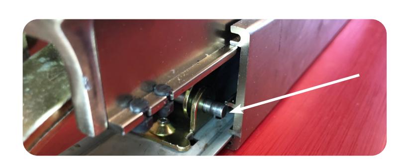
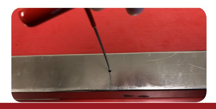
18. ONCE THE BASERAIL IS BACK INTO THE HOUSING FLIP OVER THE DEVICE & LINE UP HOLE WITH SET SCREW IN BASERAIL. LOOSEN (COUNTER CLOCKWISE) UNTIL THE SCREW IS FLUSH WITH HOUSING.

NEXT, PLUG INTO POWER SUPPLY AND TEST DEVICE. ONCE POWER IS ACHIEVED, FOLLOW STEPS FOR SET THE PUSH TO SET (PTS), REMEMBERING TO TURN THE PROGRAMMING SWITCH TO THE OFF POSITION WHEN COMPLETED.
SETTING PTS → **IMPORTANT INFO** <</p>
MAKE SURE TO SET PTS BEFORE FINISHING INSTALLATION
- STFP 1 - Select your preferred torque mode (ships in standard torque). Press the device push pad to the desired setting. (We recommend to fully depress and release 5%, giving the device room for changing door conditions.)
- STEP 2 - While depressing the push pad, apply power. (i.e. presenting the credential to the reader).
- STEP 3 Continue to keep the pad depressed, the device will beep 6 times. After the beeps have stopped, release the pad and the adjustment is now complete. If not to your liking repeat the 3 steps.
TROUBLESHOOTING & DIAGNOSTICS
| BEEPS | EXPLANATION | SOLUTION |
|---|---|---|
| 2 Beeps | Over Voltage | > 30V unit will shut down. Check voltage & adjust to 24 V. |
| 3 Beeps | Under Voltage | < 20V unit will shut down. Check voltage & adjust to 24 V. |
| 4 Beeps | Failed Sensor | Verify all 3 sensor wires are installed correctly. Replace sensor if problem persists by contacting office. |
| 5 Beeps | Retraction or dogging failure | After 1st fail: 5 beeps then immediately attempts to retract again. After 2nd fail: 5 beeps with pause in-between for 30 seconds then device attempts to retract again. After 3rd fail: 5 beeps every 7 minutes, device will not attempt to retract. To Reset: Depress bar for 5 seconds at any time. |
| 6 Beeps | PUSH TO SET | Device is recording it's new position and power mode after the 6th beep. |

*FOR MM4T *Latch bolt adjustment- If the latch bolt is not retracting far enough, turn the dial clockwise with a small flat blade screw driver. If the latch bolt is retracting too far causing the device to chatter and drop-out, turn the dial counter-clockwise until the chatter and drop-outs stop and the desired location is achieved.