models-cl10-cl20-wood-spring-latch-bolt-installation.pdf_638370
Open the original PDF document
View PDF

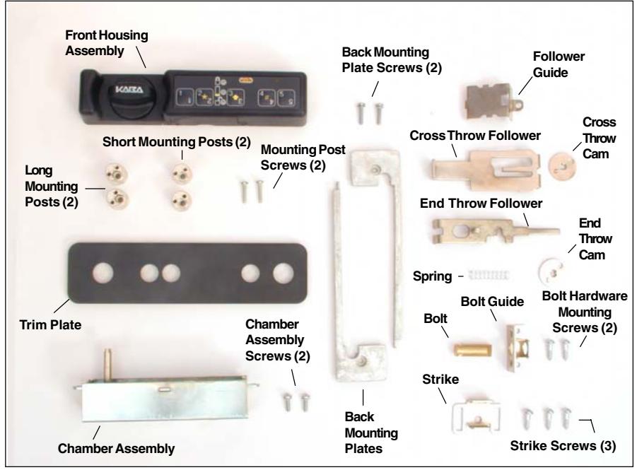
Figure 1 - Unicon CL10/CL20 Wood Spring Latch Bolt Lock Parts
These installation instructions are intended for a standard install. Please refer to the Kaba Mas web site for installation variations.
Prepare for New Installation of the Lock (If Required)
- 1. Use the template provided to prepare the mounting surface for lock installation. Complete steps A, B, and
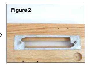
- 2. Check the width and length of the drilled lock mounting hole to ensure that the back mounting plates will fit correctly. (Figure 2)
Basic Tools and Materials Needed
- Drill (variable speed is best)
- 1" drill bit or 1" hole saw
- 1/16" (1.6mm) drill bit
- Scribe, awl, center punch, or sharp instrument for marking holes
- Small flat head screwdriver
- Small Phillips head screwdriver (recommend magnetized tip)
- Jig saw (Keyhole saw or coping saw optional)
- Fine cut wood file and rasp
- Pencil
- Tape measure or ruler
- Tape
- ESD wrist band
WARNING: Kaba Mas locks are protected from 25,000 V Electrostatic Discharge (ESD) damage when correctly installed. Follow these precautions to avoid ESD damage when installing the lock:
- . Do not touch the circuit board wthin the front housing assembly.
- . Use an ESD wrist band grounded to the lock or container during installation.
Figure 4
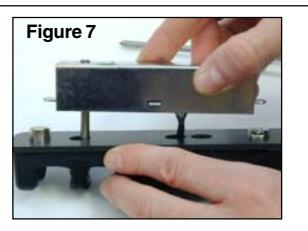
5. Insert the spindle shaft into the front housing. (Figure 7)
Note: You may have to turn the knob to engage the spindle. Do not push the cable back through into the front housing assembly. Ensure that the cable stays in place under the chamber.
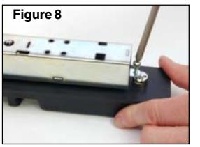
6. Install the 4-40 x 3/8" rear mounting screw (away from the spindle) to attach the chamber to the front housing. (Figure 8)
7. Place the assembly through the opening in the door with the knob toward the bolt location. (Figure 9)
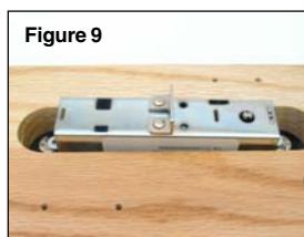
Figure 1
********* For an End Throw Installation:
(See back of sheet for Cross Throw.)
- 8. Place the cam (marked by an E on the back surface) onto the control shaft, with the post closest to the bolt location. (Figure 10)
- 10. Pivot the follower guide down

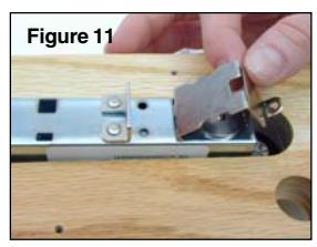
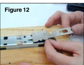
halfway and insert the follower into the slot. (Figure 12)
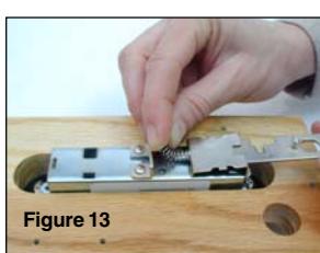
11. Feed the spring onto the back of the follower and set against the riveted bracket. (Figure 13)
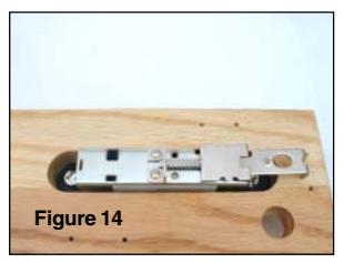
12. Move the follower forward until it engages the cam post. (Figure 14)
Install Lock
1. Place mounting posts on housing assembly and attach with 1/2" thread forming screws (without star washers.) (Figure 4) For 1/2" thick mounting surfaces, use the short mounting posts. For 5/8"-7/8" thick mounting surfaces, use the long mounting
Note: Ensure that the screw holes of the mounting posts align with the screw holes in the front housing assembly.
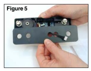
2. Orient the trim plate to the correct position in alignment with the housing assembly, and feed the cable through the middle hole. (Figure 5) Place the flat side toward the front housing assembly.
- Figure 6
- 3. Place the trim plate over the mounting posts.
- 4. Plug the cable into the chamber assembly, (Figure 6)
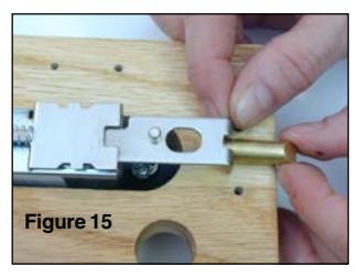
13. Insert the bolt into the bolt guide, with the beveled edge facing away from the mounting surface. (Figure 15)
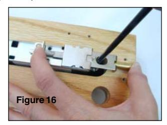
- 14. Push the follower back and hold. While using a magnetic screwdriver, insert the screw through the follower. Screw through the follower guide and chamber with the remaining 4-40 x 3/8" screw to secure the follower assembly. (Figure 16)
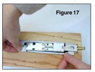
- 15. Insert the back mounting plates. (Figure 17)
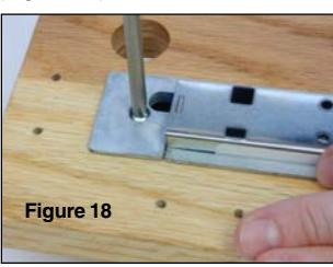
16. Secure back mounting plates with 4-40 x 1/2" screws. (Figure 18)
****************************************************************************** For a Cross Throw Installation: (See front of sheet for End Throw.)
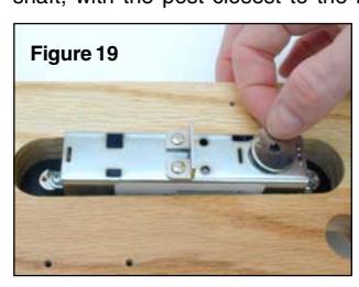
8. Place the cam (marked by a C on the back surface) onto the control shaft, with the post closest to the bolt location. (Figure 19)
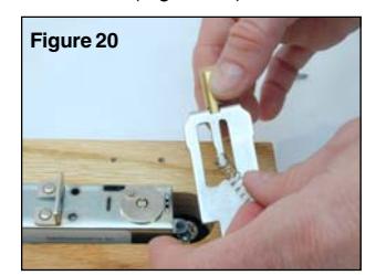
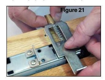
- 10. Place the legs of the follower over the bolt with the tapered side up and put the spring on the follower. (Figure 20)
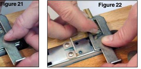
- 11. Place the follower over the chamber and cam with the follower legs engaging the bolt. (Figures 21 & 22)
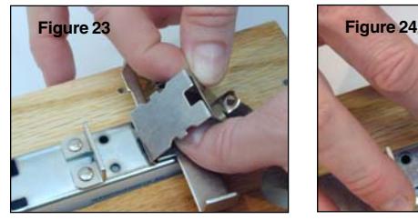
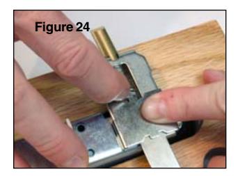
11. Insert follower guide into the slot on the chamber and pivot the follower guide down to position/retain the follower while compressing the spring to engage the notch on the follower guide. (Figures 23 & 24)
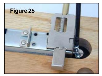
- 12. Screw through the follower guide and chamber with the remaining 4-40 x 3/8" screw to secure the follower assembly. (Figure 25)
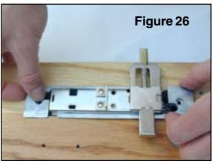
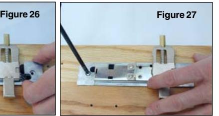
- 13. Insert the back mounting plates. (Figure 26)
- 14. Secure back mounting plates with the 4-40 x 1/2" screws. (Figure 27)
Install Bolt Hardware (If Required)
1. Insert the bolt into the bolt guide with the tapered side up.
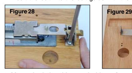
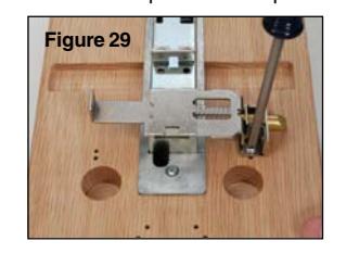
2. Mount the bolt guide onto inside surface using 2 Phillips head wood screws. (Figure 28 - End Throw, Figure 29 - Cross Throw)
Install Strike (If Required)
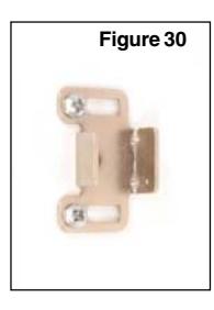
- 1. Install the strike using the two chrome Phillips head wood screws. (Figure 30)
- 2. Once adjusted, secure the center of the strike with the third chrome Phillips head wood screw.
Install Batteries
- 1. Remove the two screws from the battery panel and then remove the panel. (Figure 31)
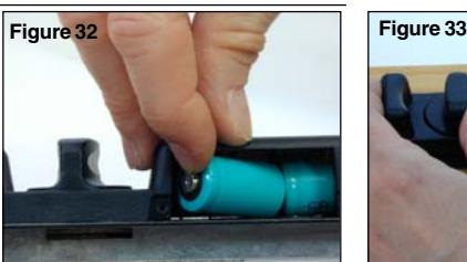
- 2. Install two fresh, high quality, name brand (Energizer® or Duracell®) CR-2 lithium batteries. (Figure 32)
Note: The negative end of the battery should be inserted into the battery cavity first.
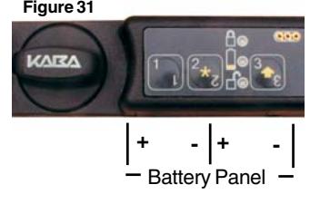
- 3. While the lock is locked, turn the knob forcefully to adjust the KABA logo to the horizontal position. (Figure 31)
- 4. Test opening of the lock with the default combination for the model you are installing: Model CL10 - "5525", Model CL20 - "111 12345".
Note: For the Model CL10, you must test the lock by toggling between locked and unlocked. To unlock, simply enter the default lock user combination of "5525". To lock the lock, enter the default lock user combination of "5525". Then press and hold the key until the yellow
light Y displays.
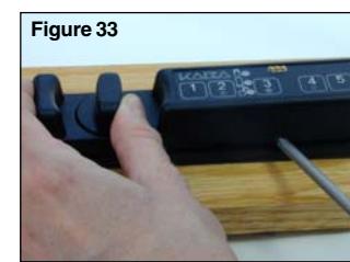
5. Reattach the battery panel (Figure 33) and test the lock once more with the default combination.
© 2006-2007 Kaba Mas Corporation. All rights reserved. Product warranty information can be found at: www.kaba-mas.com
Kaba Mas Corporation 749 W. Short Street, Lexington, KY 40508 USA Phone: (859) 253-4744 FAX: (859) 255-2655 Customer Service: (800) 950-4744