installation-of-la-gard-dial (1).pdf_419470
Open the original PDF document
View PDFLA GARD DIAL
installation of la gard dial
Read guide completely before beginning installation.
Installation instructions are the same for the entire range of LA GARD dials.
Safeguards for Mounting
- 1. Complete all welds to the safe prior to installation of the dial.
- 2.Keep metal dust, filings, etc. away from the dial.
- 3. Never oil, grease, lubricate or paint the dial.
- 1. If required, locate, drill and tap the two holes for mounting the Dial Assembly to the outside of the safe door. Use the installation template available on-line at www.kaba-mas.com.
- 2. Attach the lock assembly to the door using the three mounting screws provided. Tighten the mounting screws to a torque setting of 30 in./lbs. (3.4 N•m.) Remove the lock back cover, if applicable.
Note: Ensure the lock assembly spindle hole is properly aligned with the spindle through hole in the safe door.
- 4. Measure total mounting thickness (door thickness + mounting plate). (Figure 1.)
- 5. To cut the spindle to the proper length, add the following to the total mounting thickness:
- 0.875" (22.2mm) for 3-wheel mechanical locks
- 1.000" (25.4mm) for 4 wheel mechanical locks
- 1.125" (28.6mm) for mechanical redundant locks
- 6. Mount the dial ring centered on the through hole, and attach to the safe door using the two mounting screws supplied with the dial assembly. The opening index reference mark must be in the twelve o'clock position. (Figure 2.)
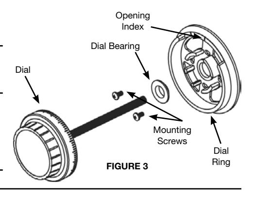
- 7. Place the dial bearing onto the dial ring. (Figure 3.)
- 8. Insert the spindle through the spindle hole in the front of the door.
- 9. With the bolt retracted, carefully thread (clockwise) the spindle into the drive cam of the lock assembly until tight.
Note: It is recommended the lock bolt remain in the retracted position throughout the installation procedure. To ensure this, keep one finger over the bolt while installing the dial spindle into the lock cam.
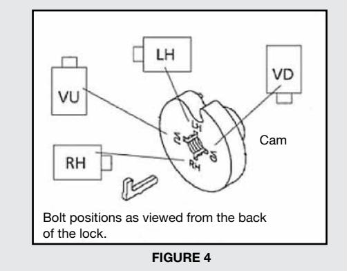
- 10. Next, rotate (counterclockwise) at least 1/2 turn until the groove in the spindle is aligned with the correct spline position. (Refer to the Spline Key Position Chart - Figure 4.)
- 11. Insert the spline key fully into the cam from the back of the lock assembly by tapping it into place.
Important Note: Ensure the spline key is seated against the spindle.
12. Either reinstall the back cover or insert spindle cover (3390 model).
Spline Key Position Chart
The lock may be mounted in four positions - align the spindle groove with the corresponding cam position. The positions are marked as follows:
- RH (right hand)
- Lock bolt points right as you view the lock from the back side of the door.
- • LH (left hand)
- Lock bolt points left as you view the lock from the back side of the door.
- • VU (vertical up)
- Lock bolt points upward.
- • VD (vertical down)
- Lock bolt points downward.
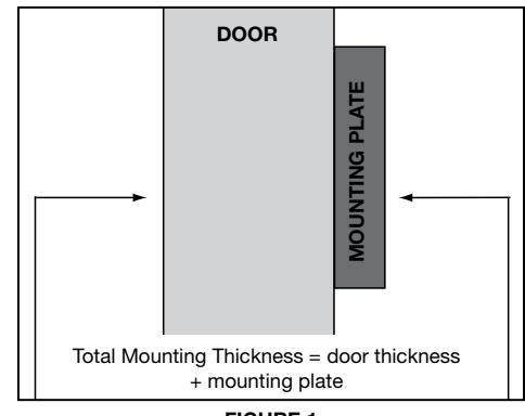

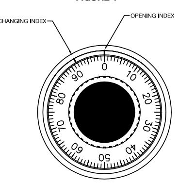
Figure 2