installation-instructions-for-unicon-cl-series-locks-model-cl20-metal-dead-bolt-installation.pdf_638352
Open the original PDF document
View PDF

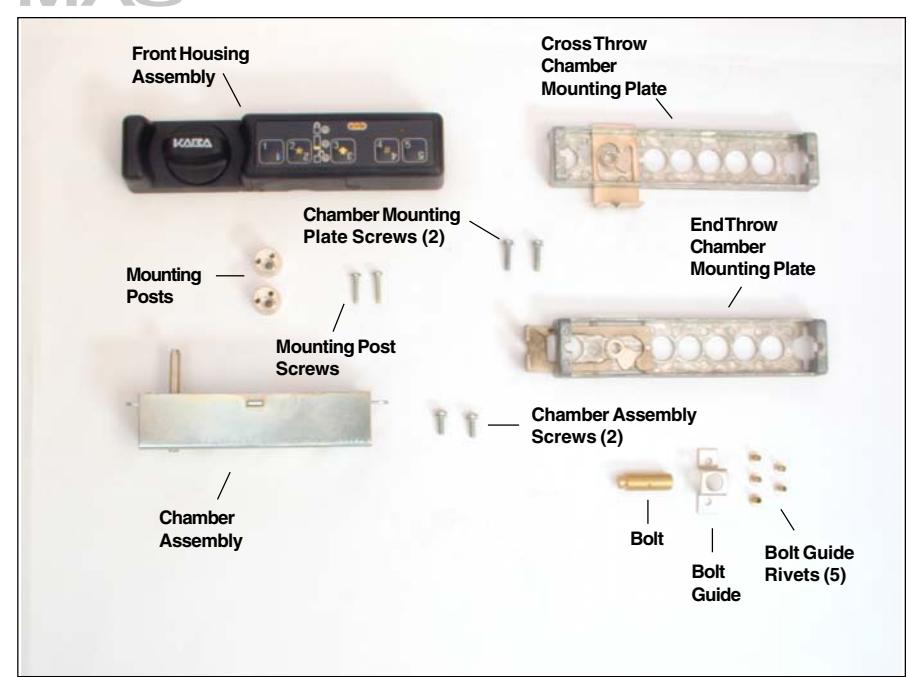
Figure 1 - Unicon CL20 Metal Dead Bolt Lock Parts
These installation instructions are intended for a standard install. Please refer to the Kaba Mas web site for installation variations.
Prepare for New Installation of the Lock (If Required)
- 1. Verify the position fo the strike (if applicable) before preparing the mounting surface for installation.
- 2. Use the template provided to prepare the mounting surface for lock installation. Complete steps A, B, and C.
Install Bolt Hardware (If Required)
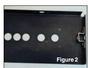
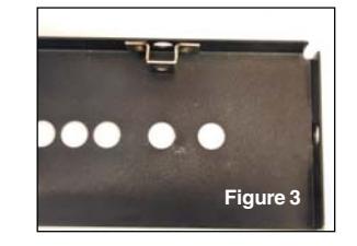
1. Mount bolt guide onto inside surface using rivets provided. (Figure 2 -End Throw, Figure 3 - Cross Throw)
Basic Tools and Materials Needed
- Drill (variable speed is best)
- 1" drill bit or 1" hole saw
- 1/8" (3mm) drill bit
- 5/16" (8mm) drill bit or step drill
- 7/16" (11mm) drill bit or step drill
- Scribe, awl, center punch, or sharp instrument for marking holes
- Fine round metal file or or deburring tool to remove all sharp edges
- Small Phillips head screwdriver (recommend magnetized tip)
- Pencil
- Tape measure or ruler
- Tape
- ESD wrist band
WARNING: Kaba Mas locks are protected from 25,000 V Electrostatic Discharge (ESD) damage when correctly installed. Follow these precautions to avoid ESD damage when installing the lock:
- . Do not touch the circuit board wthin the front housing assembly.
- . Use an ESD wrist band grounded to the lock or container during installation.
- 4. Ensure that the follower is still in the locked position (pulled forward) and align the holes in the back mounting plate with the holes in the mounting surface.
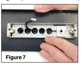
- 5. Orient the front housing assembly to the correct position in alignment with the mounting surface, and feed the cable through the middle hole of the mounting surface and the back mounting plate while also aligning the posts with the holes. (Figure 7)
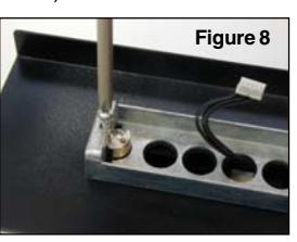
- 6. Install the rear 4-40 x 1/2" mounting screw (away from the spindle) to attach the chamber plate to the front housing. (Figure 8)
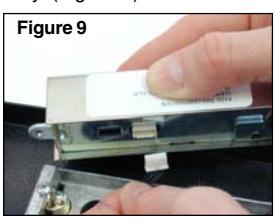
- 7. Plug the cable from the front housing assembly into the chamber assembly. (Figure 9)
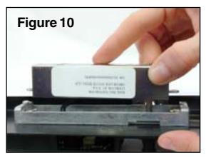
8. Insert the spindle shaft into the front housing through the chamber plate. (Figure 10)
Note: You may have to turn the knob to engage the spindle.
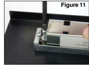
- 9. Install the rear 4-40 x 3/8" mounting screw (away from the spindle) to attach the chamber to the front housing. (Figure 11)
- 10. Install the front 4-40 x 3/8" mounting screw (closest to the bolt) to attach the chamber to the front housing. (Figure 12)
Figure 12
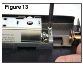
11. Install the front 4-40 x 1/2" mounting screw (next to the bolt) to attach the chamber plate to the front housing. (Figure 13)
Install Lock
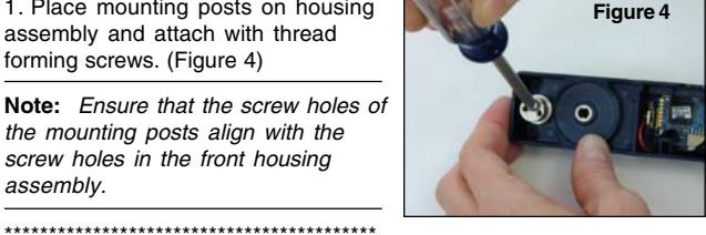
1. Place mounting posts on housing assembly and attach with thread forming screws. (Figure 4)
Note: Ensure that the screw holes of the mounting posts align with the screw holes in the front housing assembly.
For an End Throw Installation:
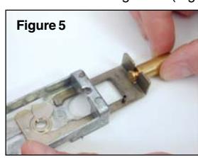
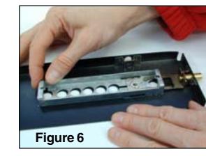
- 2. Pull the follower all the way forward to the locked position and place the bolt in the follower. (Figure 5)
- 3. Place the back plate assembly with bolt on the inside mounting surface of the cabinet or container and slide the assembly to place the bolt into the bolt guide. (Figure 6)
******************************************* For a Cross Throw Installation:
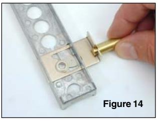
- 2. Pull the follower all the way forward to the locked position and place the bolt in the follower. (Figure 14)
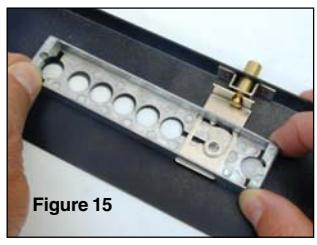
- 3. Place the back plate assembly with bolt on the inside mounting surface of the cabinet or container and slide the assembly to place the bolt into the bolt guide. (Figure 15)
4. Ensure that the follower is still in the locked position (pulled forward) and align the holes in the back mounting plate with the holes in the mounting surface.
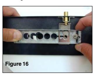
- 5. Orient the front housing assembly to the correct position in alignment with the mounting surface, and feed the cable through the middle hole of the mounting surface and the back mounting plate while also aligning the posts with the holes. (Figure 16)
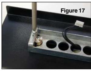
- 6. Install the rear 4-40 x 1/2" mounting screw (away from the spindle) to attach the chamber plate to the front housing. (Figure 17)
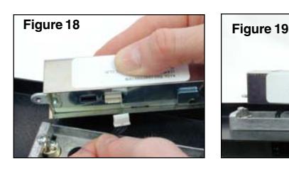
- 7. Plug the cable from the front housing assembly into the chamber assembly. (Figure 18)
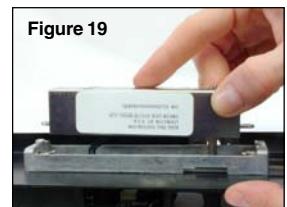
8. Insert the spindle shaft into the front housing through the chamber plate. (Figure 19)
Note: You may have to turn the knob to engage the spindle.
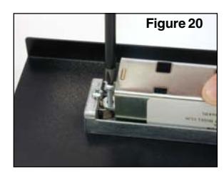
9. Install the rear 4-40 x 3/8" mounting screw (away from the spindle) to attach the chamber to the front housing. (Figure 20)
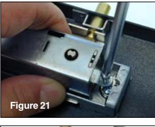
- 10. Install the front 4-40 x 3/8" mounting screw (closest to the bolt) to attach the chamber to the front housing. (Figure 21)
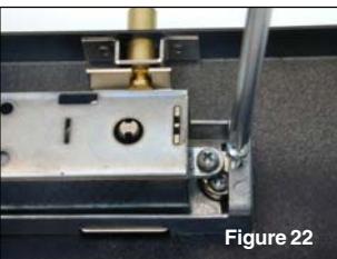
- 11. Install the front 4-40 x 1/2" mounting screw (next to the bolt) to attach the chamber plate to the front housing. (Figure 22)
Install Batteries
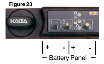
- 1. Remove the two screws from the battery panel and then remove the panel. (Figure 23)
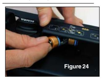
- 2. Install two fresh, high quality, name brand (Energizer® or Duracell®) CR-2 lithium batteries. (Figure 24)
Note: The negative end of the battery should be inserted into the battery cavity first.
- 3. Test opening of lock with default combination of "111 12345".
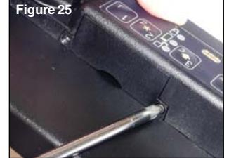
- 4. Reattach the battery panel (Figure 25) and test the lock once more with the default combination.
- 5. Turn the knob to adjust the KABA logo to the horizontal position. (Figure 23)
© 2006 Kaba Mas Corporation. All rights reserved. Product warranty information can be found at: www.kaba-mas.com
Kaba Mas Corporation 749 W. Short Street, Lexington, KY 40508 USA Phone: (859) 253-4744 FAX: (859) 255-2655 Customer Service: (800) 950-4744