i-ed01571 (1)
Open the original PDF document
View PDF

DEVICES COVERED IN THIS DOCUMENT:
45MC, 45MN, 45MB and 45MD MORTISE LOCK EXIT DEVICE TRIM
| Fasteners and Other Parts Included | Quantity | Purpose |
|---|---|---|
| ¼"-20 x ¾" Pan Head Machine Screws | 2 | Through-bolting to wood or metal doors |
| Handing Pin | 1 | Used to set handing for trim |
| Cylinder Wave Spring (not shown) | 1 | Helps fasten cylinder to mortise body |
| Cylinder Spacing Ring (not shown) | 1 | Helps fasten cylinder to mortise body |
1. PREPARE DOOR
The Hager Exit device is designed to fit a door and frame prepared for a Mortise Lock per ANSI/BHMA A156.115-2016. The holes and cutouts specifically for the Hager Mortise Lock Exit Device are shown in the template T-ED01545 and in the Door Preparation Drawing S-ED01546. See www.hagerco.com for additional information.
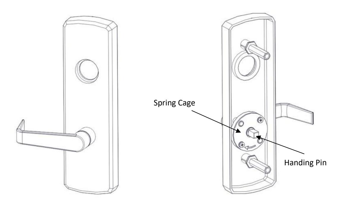
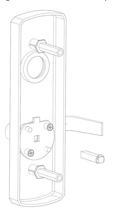
2. HAND TRIM (MB AND MC TRIM ONLY)
Make sure the handle is oriented to the side of the escutcheon that corresponds with the door handing. Make sure the spring cage is oriented so the arrow is pointing in the direction of the desired handle rotation. If it is not oriented properly, remove the two screws and rotate the spring cage 180 degrees and reinstall the screws. Install the handing pin.
Rev 4, Rev Date: 4/21/22 Page 1 of 3

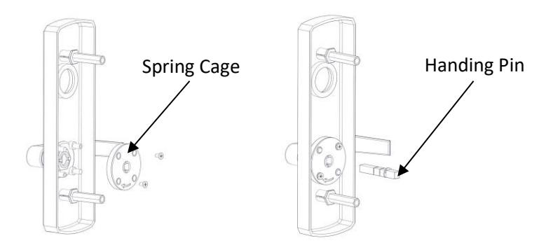
3. HAND TRIM (MN AND MD TRIM ONLY)
For handing the MN and MD trim there is no spring cage. Position the handle in the proper orientation and install the handing pin.
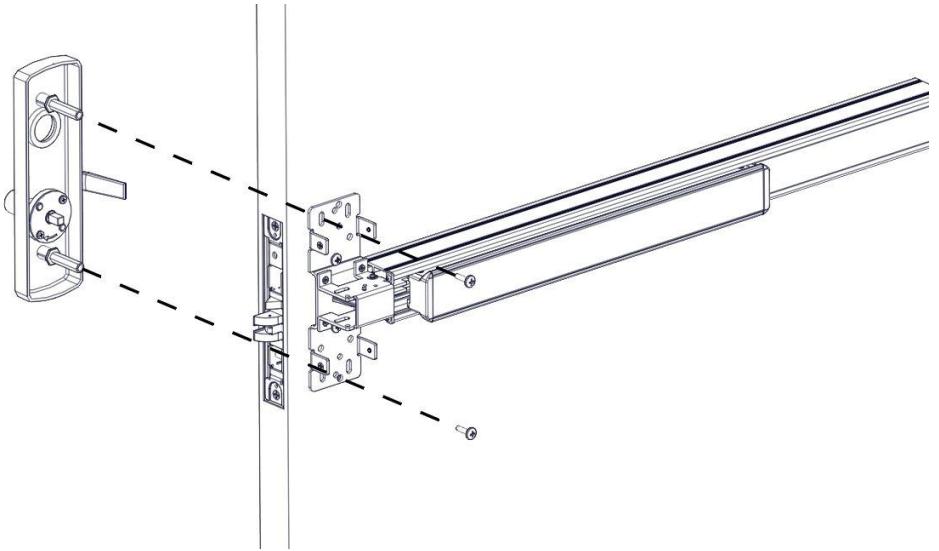
4. INSTALL TRIM
Install the trim on the pull side of the door insuring that the handing pin is properly inserted into the lock body. The handing pin only interacts with the lock body for the MC and MB trim. Use the supplied screws to bolt the trim to the door through the exit device chassis.
Rev 4, Rev Date: 4/21/22 Page 2 of 3

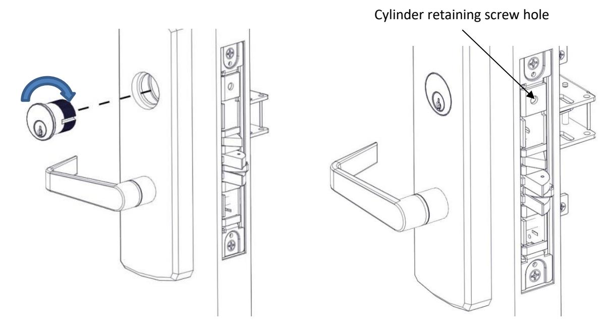
5. INSTALL MORTISE CYLINDER (MC AND MN TRIM ONLY)
Loosen the cylinder retaining screw to allow the cylinder to be threaded into the lock case by inserting a screw driver with a #2 tip in the hole on the mortise lock body. Install the mortise cylinder in the trim. Screw the cylinder into the lock body. The keyway must end up on the bottom of the cylinder housing. Secure the cylinder by tightening the retaining screw. A 1-5/8" long cylinder is required for these functions.
Rev 4, Rev Date: 4/21/22 Page 3 of 3