i-ea00281-acm
Open the original PDF document
View PDFHS4 ACCESS POWER CONTROLLERS Installation Instructions I-EA00281
2-679-0997, 2-679-0998
Overview:
Hager kits are pre-assembled and consist of enclosure/backplane with factory installed power supply/charger(s) and sub-assemblies. These kits also accommodate various combinations of HS4 modules for up to twelve (12) doors in a single enclosure.
Specifications:
Inputs:
- Input Ratings: 12VDC @ 0.4A or 24VDC @ 0.2A.
-
Power supply input options:
- a) One (1) common power input (board and lock power).
- b) Two (2) isolated power inputs (one (1) for board power and one (1) for lock/hardware power).
-
Four (4) 2-679-0997 or Eight (8) 2-679-0998 Access Control System trigger inputs:
- a) Normally open (NO) inputs.
- b) Open collector sink inputs.
- c) Any combination of the above.
Outputs:
-
Four (4) 2-679-0997 or Eight (8) 2-679-0998 independently controlled outputs:
- a) Fail-Safe and/or Fail-Secure power outputs.
- b) Dry form "C" 5A rated relay outputs.
- c) Any combination of the above.
Outputs (cont'd):
Four (4) 2-679-0997 or Eight (8) 2-679-0998 auxiliary power outputs (unswitched).
Fuse Ratings:
- Output ratings: 2-679-0997 2.5A each, 2-679-0998 3.5A each.
- Main fuse is rated at 10A.
- Note: Operating temperature range should be 0 to 49°C.
Fire Alarm Disconnect:
-
Fire Alarm disconnect (latching or non-latching) is individually selectable for any or all of the four (4) or eight (8) outputs. Fire Alarm disconnect input options:
- a) Normally open (NO) or normally closed (NC) dry contact input.
- b) Polarity reversal input from FACP signaling circuit.
- FACP output relay (form "C" contact rated @ 1A/28VDC, not evaluated by UL).
LED Indicators:
- Red LEDs indicate outputs are triggered (relays energized).
- Green LED indicates when FACP disconnect is triggered.

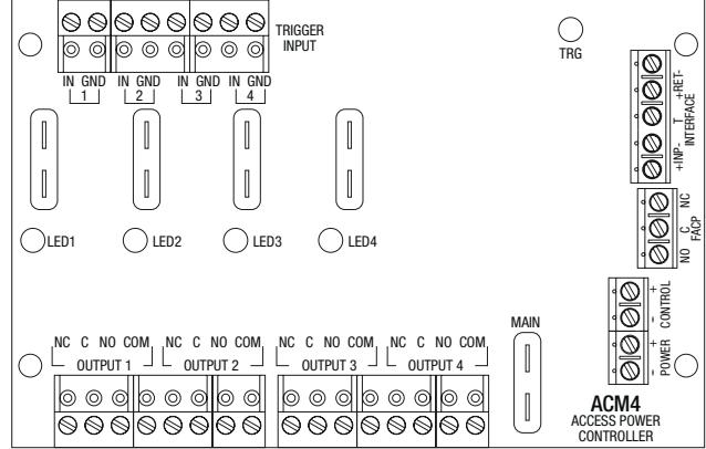
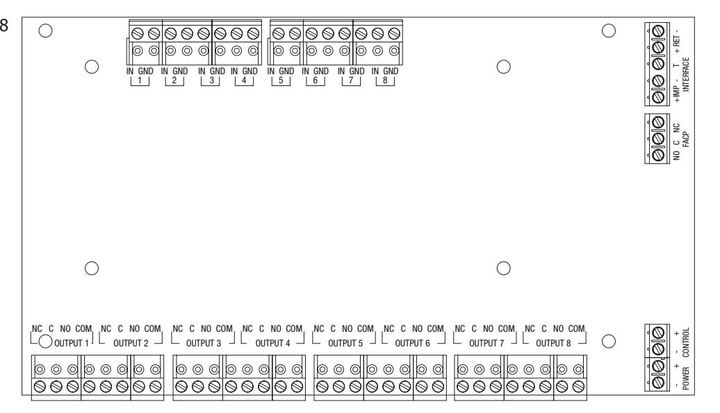
Fig. 2 - 2-679-0998
Rev - , Rev Date: 08/19/19

HS4 ACCESS POWER CONTROLLERS Installation Instructions I-EA00281
2-679-0997, 2-679-0998 :
1. Output options (Fig. 1-2, pg. 1):
The unit will provide either four (4) or eight (8) switched power outputs, four (4) or eight (8) dry form "C" outputs, or any combination of both switched power and form "C" outputs.
- (a) Fail-Safe Switched Power outputs: Connect the positive (+) input of the access control devices to terminal marked [NC]. Connect the negative (–) input of the access control devices to terminal marked [COM].
-
(b) Fail-Secure Switched Power outputs: Connect the positive (+) input of the access control devices to terminal marked [NO]. Connect the negative (–) input of the access control devices to terminal marked [COM].
- (c) Form "C" outputs: Remove corresponding output fuses (1-4) of 2-679-0997 or (1-8) of 2-679-0998 board.
- 2. Auxiliary Power outputs (unswitched): Connect access control devices that require constant power to terminals marked [C] positive (+) and [COM] negative (–). Outputs can be used to provide power for card readers, keypads etc.
- 3. Input trigger options:
- (a) Normally Open [NO] input trigger: Inputs 1-4 or 1-8 are activated by normally open or open collector sink inputs. Connect access control panel outputs, keypads, push buttons, REX PIRs, etc. to terminals marked [IN] and [GND].
- (b) Open Collector Sink inputs: Connect the access control panel open collector sink positive (+) to terminals marked [IN] and the negative (–) to terminals marked [GND].
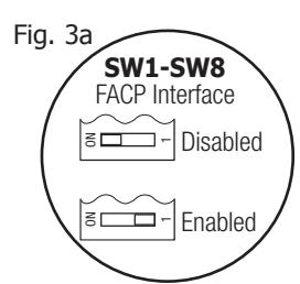
- 4. Fire Alarm Interface options (Fig. 3a, pg. 2): A normally closed [NC] or normally open [NO] input trigger trigger from a fire alarm control panel or a polarity reversal input from an FACP signaling circuit will affect selected outputs. To enable FACP Disconnect for an output turn the corresponding switch(es) [SW1-SW4/SW8] OFF on 2-679-0997/2-679-0998 board. To disable FACP disconnect for an output turn the corresponding switch(es) [SW1-SW4/SW8] ON the 2-679-0997/2-679-0998 board.
- (a) Normally Open [NO] input: For non-latching hook-up refer to Fig. 6, pg. 3. For latching hook-up refer to Fig. 7, pg. 3.
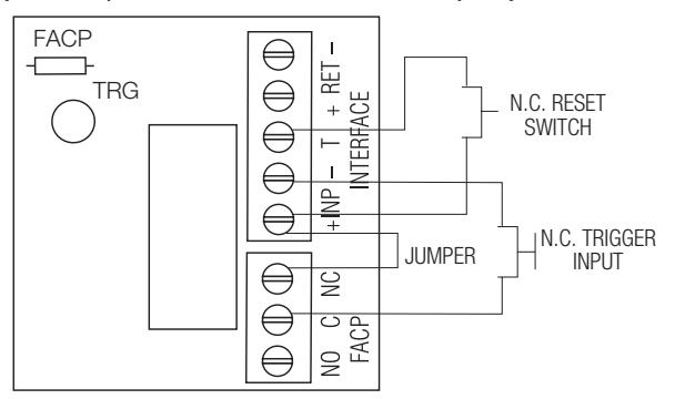
- (b) Normally Closed [NC] input: For non-latching hook-up refer to Fig. 8, pg. 3. For latching hook-up refer to Fig. 9, pg. 3.
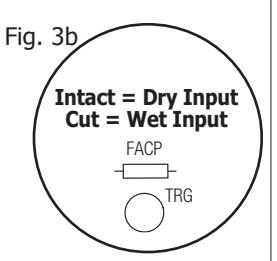
- (c) FACP Signaling Circuit input trigger: Connect the positive (+) and negative (–) from the FACP signaling circuit output to the terminals marked [+ INP –]. Connect the FACP EOL to the terminals marked [+ RET -] (polarity is referenced in an alarm condition). Jumper located next to TRG LED must be cut (Fig. 3b, pg. 2).
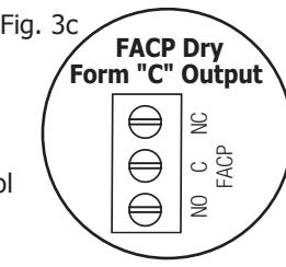
- 5. FACP Dry form "C" output (Not evaluated by UL) (Fig. 3c, pg. 2): FACP form "C" contacts can be used to trigger reporting or signaling devices. These contacts switch upon a fire alarm input trigger to the 2-679-0997/2-679-0998 board(s).
- 6. Fire Alarm Disconnect: To enable Fire Alarm Disconnect set DIP switch [Shutdown] to ON position. To disable Fire Alarm Disconnect set DIP switch [Shutdown] to OFF position.
- 7. Multiple power supply inputs (Fig. 4, pg. 3) (Not evaluated by UL): When using an additional Listed external power supply, jumpers J1 and J2 located on corresponding 2-679-0997/2-679-0998 board must be cut (Fig. 4, pg. 3). Connect external Listed power-limited access control power supply to the terminals marked [– Control +] (These terminals are paralleled to the [– Power +] terminals). When using DC power supplies, polarity must be observed. All field wiring connections must be made employing suitable gauge CM or FPL jacketed wire (or equivalent substitute).
LED Diagnostics:
| LED | ON | OFF |
|---|---|---|
| LED 1- LED 8 (Red) |
Output relay(s) energized.
Output relay(s) de-energized. |
|
| Trg (Green) | FACP input triggered (alarm condition). | FACP normal (non-alarm condition). |
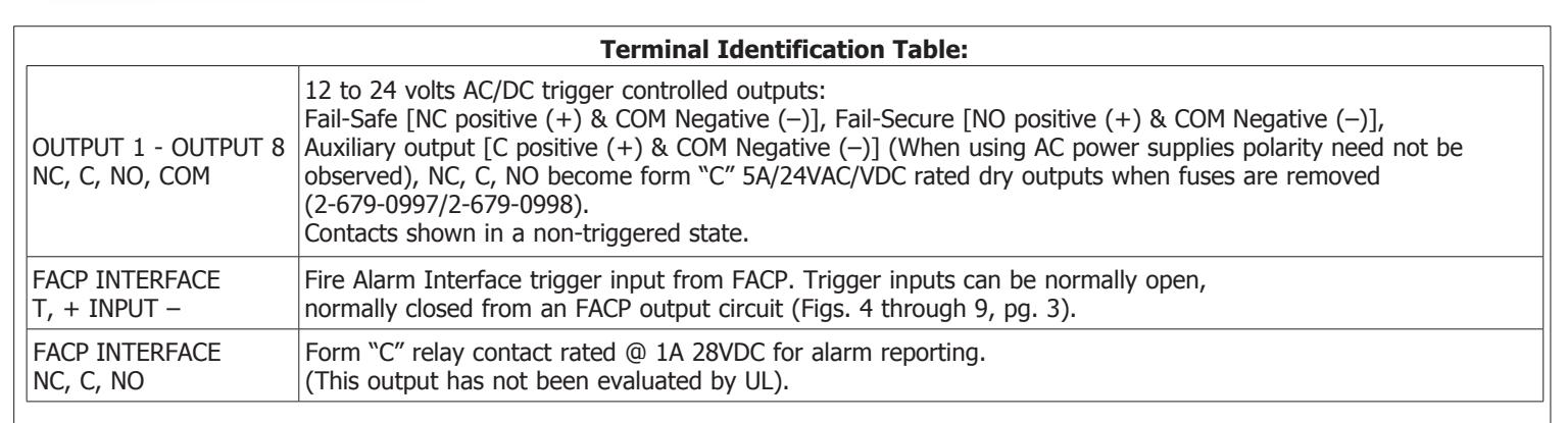
Terminal Identification Table:
| Terminal Legend | Function/Description |
|---|---|
| – Power + | 12VDC or 24VDC input from power supply board. |
| – Control + |
These terminals can be connected to a separate UL Listed power supply to provide
isolated operating power for the 2-679-0997/2-679-0998 (jumpers J1 and J2 must be removed). |
|
TRIGGER
INPUT 1 - INPUT 8 IN, GND |
From normally open and/or open collector sink trigger inputs
(request to exit buttons, exit pir's, etc.). |

Hook-Up Diagrams:
power supply inputs: (polarity is referenced in alarm condition):
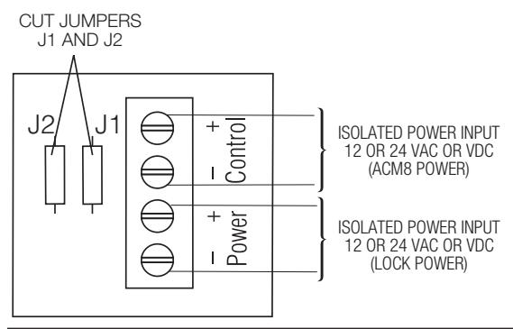
Fig. 4 - Optional hook-up using two (2) isolated Fig. 5 - Polarity reversal input from FACP signaling circuit output
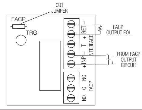
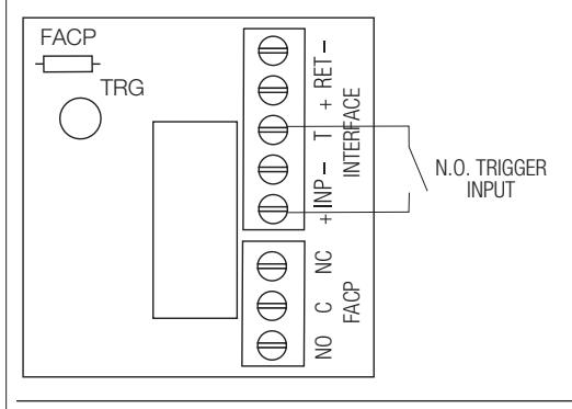
Fig. 6 - Normally Open: Non-Latching FACP trigger input: Fig. 7 - Normally Open FACP Latching trigger input with reset (This output has not been evaluated by UL):
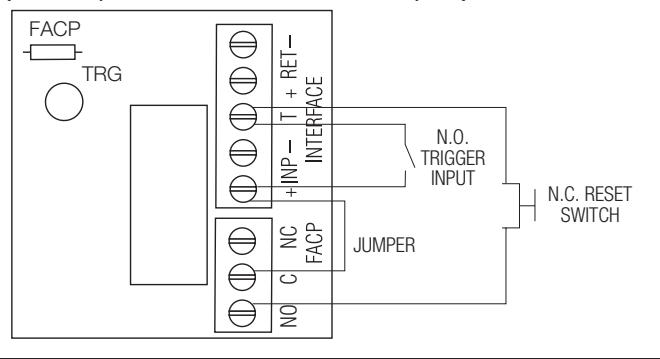
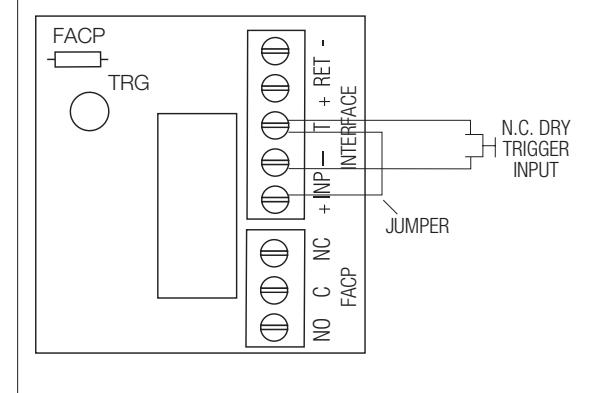
Fig. 8 - Normally Closed Non-Latching FACP trigger input: Fig. 9 - Normally Closed Latching FACP trigger input with reset (This output has not been evaluated by UL):

HS4 ACCESS POWER CONTROLLERS Installation Instructions I-EA00281
| Notes: |
|---|
| Installing Company: Service Rep. Name: |
| Address: Phone #: |