i-cl00796-rev05
Open the original PDF document
View PDF

5400 Series Non-Hold Open Door Closer
Installation Instructions
Adjustable 2-5 I-CL00796 Rev. 5 4-12-2023
DOOR CLOSER ADJUSTMENTS
NOTE : Closing arcs("CLOSE"and"LATCH") are controlled by two(2)separate speed adjusting valves. Adjust the CLOSING speed at first and then adjust the LATCHING speed.
-
1. "CLOSING" speed adjustment is accomplished by full rotations of the speed adjusting valve.
- -Turn the speed adjusting valve CLOCKWISE for a SLOWER closing speed.
- -Turn the speed adjusting valve COUNTER-CLOCKWISE for a FASTER closing speed.
-
2 "LATCH" speed adjustment is accomplished by full rotations of the speed adjusting valve.
- -Turn the speed adjusting screw CLOCKWISE for a SLOWER closing speed.
- -Turn the speed adjusting screw COUNTER-CLOCKWISE for a FASTER closing speed.
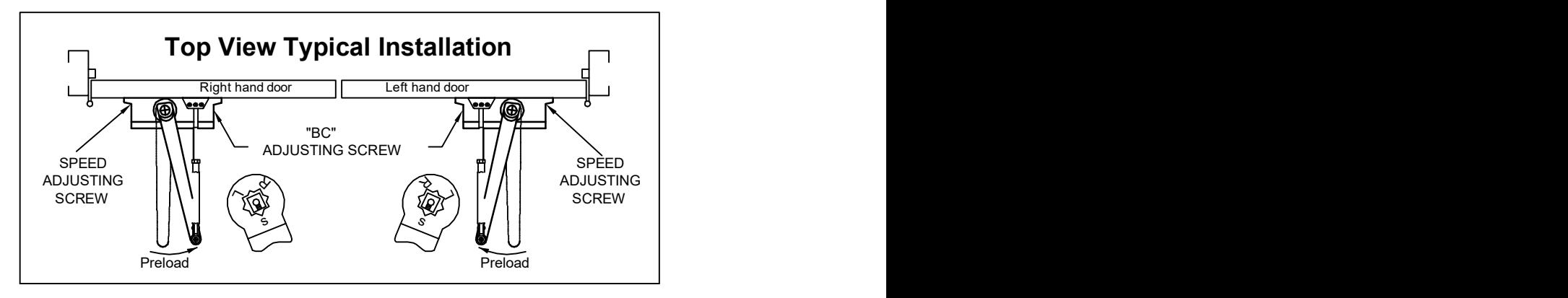
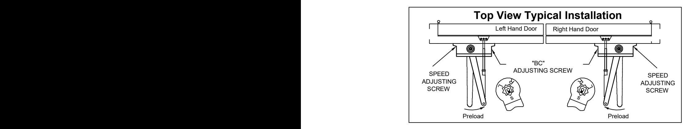
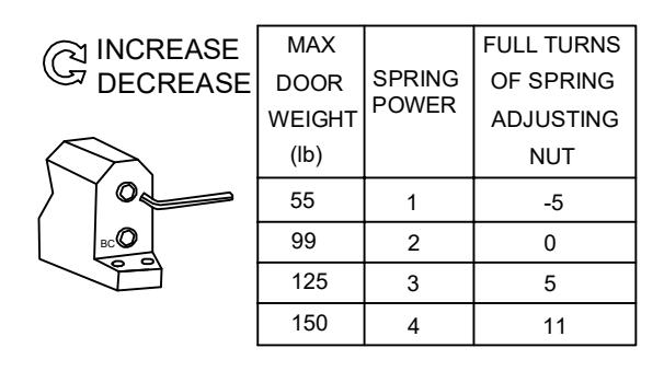
BACKCHECK ADJUSTMENT
NOTE: These instructions apply only to closers equipped with backcheck action. To increase backcheck intensity, turn "BC" valve clockwise. To decrease backcheck intensity, turn "BC" Valve counter-clockwise.
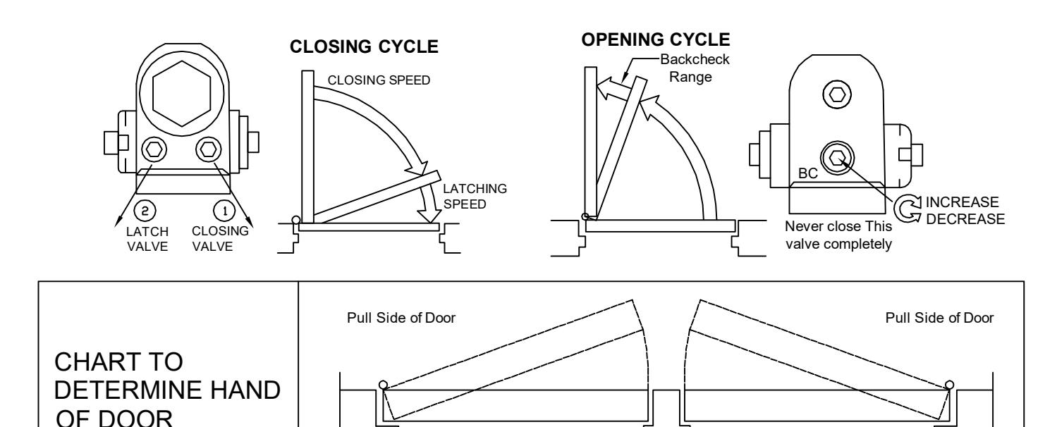
THIS IS A LEFT HAND DOOR
Push Side of Door
Push Side of Door
THIS IS A RIGHT HAND DOOR

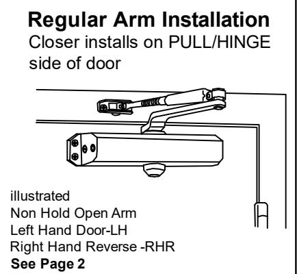
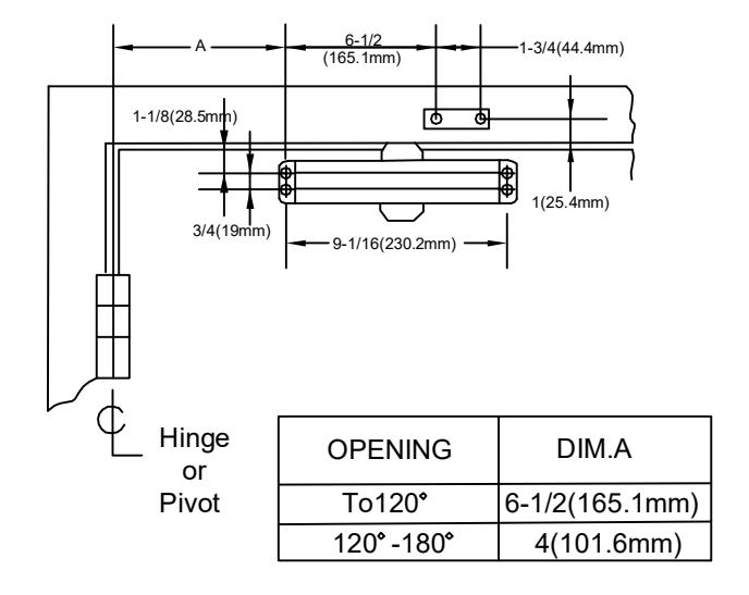
REGULAR ARM (PULL SIDE) Mounting TO 180° OPENINGS.
*ADJUST SPRING TENSION ACCORDING TO THE DOOR WIDTH & WEIGHT
|
IN
C R EA S E |
MA
X |
FU
LL T UR NS |
|
|
C
S D E R EA E |
DO
O R |
SP
RI NG |
O
F SP RI NG |
|
W
EI G HT |
PO
W ER |
ST
G AD JU IN |
|
|
(lb
) |
NU
T |
||
| 99 | 2 | -5 | |
| BC |
12
5 |
3 | 0 |
|
15
0 |
4 | 5 | |
|
19
8 |
5 | 11 | |
NOTE: MAX 16 TURNS FROM MINIMUM SETTING
- Right hand door shown
- Left hand door opposite
- Dimensions are in inches(mm)
- Do not scale drawing
INSTALLATION SEQUENCE
- 1. Select door opening angle and use dimensions shown above. Mark four (4) holes on door leaf for closer body and two (2) holes on frame for arm shoe.
- 2. Drill pilot holes in door leaf and frame for #14 all-purpose screws for wood door/frame. Or drill and tap for 1/4-20 machine screws for metal door/frame
- 3. Install forearm/arm shoe assembly to frame using provided screws.
- 4. Mount closer on door using provided screws. SPEED ADJUSTING VALVE MUST BE POSITIONED TOWARD HINGE EDGE
- 5. Install main arm to top pinion shaft, perpendicular to door. Secure tightly with provided arm screw/washer assembly.
- 6. Adjust length of forearm so that forearm is perpendicular to frame when assembled to preloaded main arm (see below iIlustration). Secure forearm to main arm with provided screw/washer assembly
- 7. Snap pinion cap over shaft at bottom of closer. If the slim cover is packed, please fix it by provided screws.
- 8. Adjust the door closer, following instructions as shown on page 1.

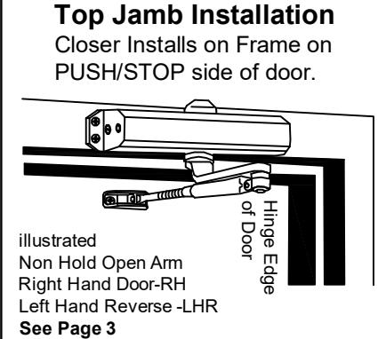
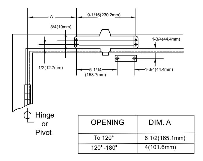
TOP JAMB (PUSH SIDE) Mounting TO 180° OPENINGS.
*ADJUST SPRING TENSION ACCORDING TO THE DOOR WIDTH & WEIGHT
|
IN
C R EA S E |
MA
X |
FU
LL T UR NS |
|
|---|---|---|---|
|
D
EC R EA S E |
DO
O R |
SP
RI NG |
O
F SP RI NG |
|
W
EI GH T |
PO
W ER |
AD
JU ST IN G |
|
|
(lb
) |
NU
T |
||
| 99 | 2 | -5 | |
| BC |
12
5 |
3 | 0 |
|
15
0 |
4 | 5 | |
|
19
8 |
5 | 11 |
NOTE: MAX 16 TURNS FROM MINIMUM SETTING
- Left hand door shown
- Right hand door opposite
- Dimensions are in inches(mm)
- Do not scale drawing
INSTALLATION SEQUENCE
- 1. Select door opening angle and use dimensions shown above. Mark four (4) holes on door frame for closer body and two (2) holes on door leaf for arm shoe.
- 2. Drill pilot holes in door leaf and frame for #14 all-purpose screws for wood door/frame. Or drill and tap for 1/4-20 machine screws for metal door/frame
- 3. Install forearm/arm shoe assembly to door leaf using provided screws.
- 4. Mount closer on door frame using provided screws. SPEED ADJUSTING VALVE MUST BE POSITIONED TOWARD HINGE EDGE
- 5. Install main arm to bottom pinion shaft, perpendicular to door frame. Secure it tightly with provided arm screw/washerassembly.
- 6. Adjust length of forearm so that forearm is perpendicular to door leaf when assembled to preloaded main arm (see below iIlustration). Secure forearm to main arm with provided screw/washer assembly
- 7. Snap pinion cap over shaft at top of closer. If the slim cover is packed, please fix it by provided screws.
- 8. Adjust the door closer, following instructions as shown on page 1.

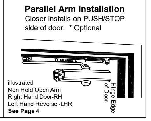
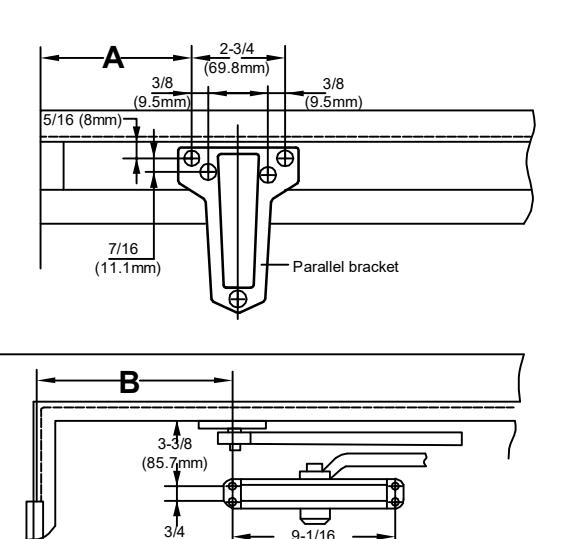
PARALLEL ARM (PUSH SIDE) Mounting TO 180° OPENINGS.
Left hand door shown
¢ L Hinge or Pivot
• Right hand door opposite
(19mm)
- Dimensions are in inches (mm)
- Do not scale drawing
*ADJUST SPRING TENSION ACCORDING TO THE DOOR WIDTH & WEIGHT
*NOTE: MAX 16 TURNS FROM MINIMUM SETTING
| OPENING | DIM.A | DIM.B |
|---|---|---|
| To 120° |
10 3/4
(273mm) |
6 15/16
(176.2mm) |
| 120°-180° |
8 3/4
(222.2mm) |
4 3/4
(120.6mm) |
INSTALLATION SEQUENCE
- 1. Select door opening angle and use dimensions shown above. Mark four (4) holes on door for door closer and four(4) holes underside of frame for paralle I bracket.
- 2. Drill pilot holes in door leaf and frame for #14 all-purpose screws for wood door/frame. Or drill and tap for 1/4-20 machine screws for metal door/frame.
- 3. Mount closer on door using provided screws.
SPEED ADJUSTING VALVE MUST BE POSITIONED AWAY FROM HINGE EDGE
- 4. Install parallel Arm Bracket to frame using provided screws.
- 5. Using a wrench on the square shaft at bottom of closer, rotate shaft approximately 45 degrees toward hinge edge of door. Hold and place main arm on top shaft of closer at proper index mark as illustrated.
FOR LEFT HAND DOOR "L"(illustration "A"). FOR RIGHT HAND DOOR "R"(illustration "B"). Tighten arm screw with Lock-washer securely.
- 6. Remove arm shoe from forearm and discard. Install rod end of forearm to bracket using provided screw/washer assembly. 7. Adjust length of adjustable forearm so that main arm is parallel to frame.
-
8. Adjust the door closer, following instuctions as shown on page 1.
- Parallel arm Installation Left hand door A5° Right hand door Speed screws (A)