hinges-brochure
Open the original PDF document
View PDFCOMMERCIAL HINGES
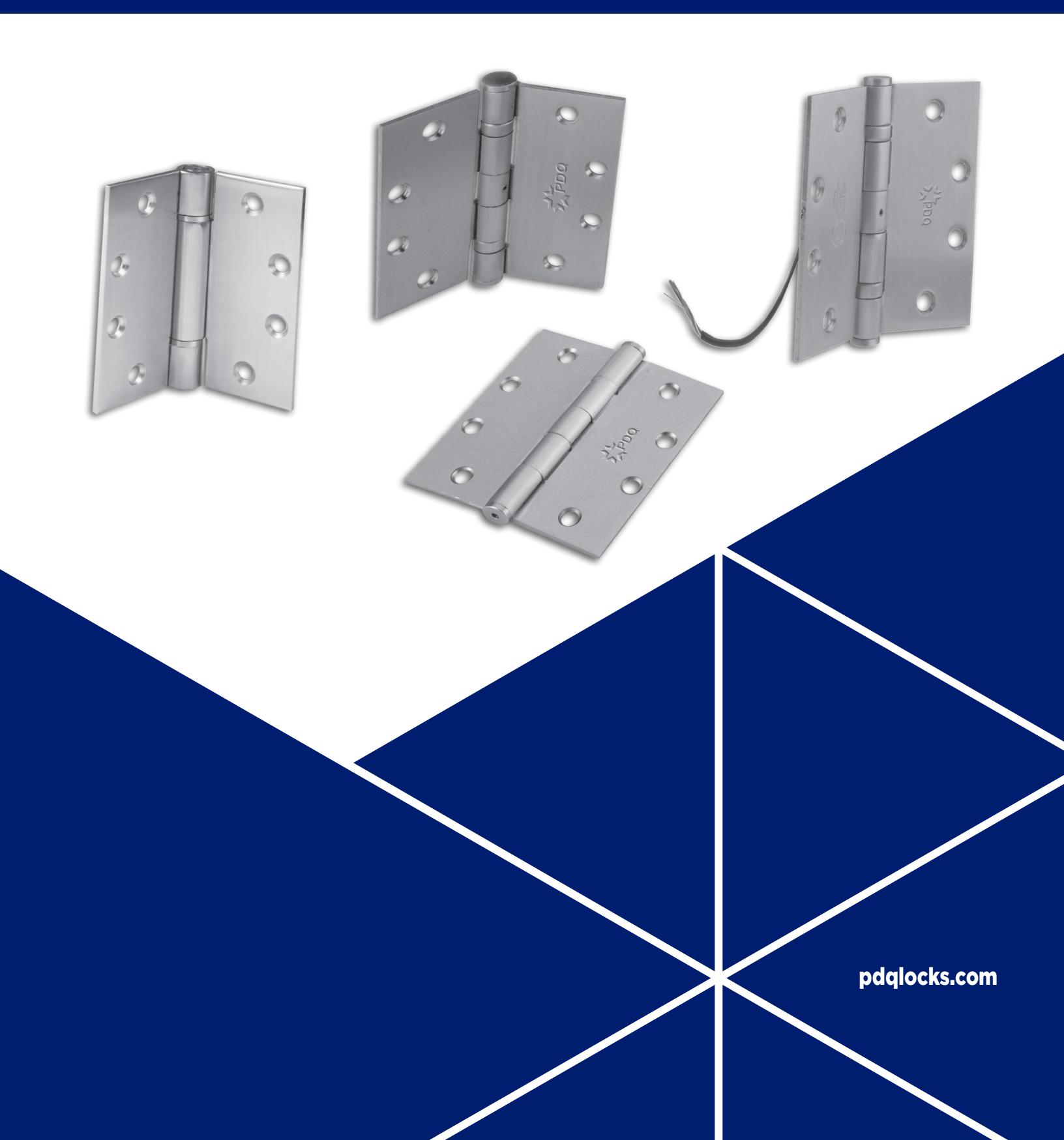
Table of Contents
| FEATURES AND SPECIFICATIONS2 | |
|---|---|
| ANSI/BHMA FULL MORTISE BUTT HINGES3-4 | |
| SPRING HINGES4 | |
| ELECTRIFIED HINGES5 | |
| HOW TO ORDER GUIDE5 | |
| QUICK REFERENCE GUIDE6 | |
| RECOMMENDED NUMBER OF HINGES, HINGE LOCATIONS, HINGES WIDTHS | 7 |
| HINGE WIDTH FORMULA, TYPICAL DOOR WEIGHTS | 8 |
| HINGE SELECTION FOR LABELED FIRE DOORS9-10 | |
| HANDING AND FINISHES10 | |
| CROSS REFERENCE | 11 |
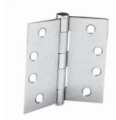

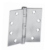
2 BALL BEARING STANDARD WEIGHT
4 BALL BEARING HEAVY WEIGHT
SPRING HINGE STANDARD WEIGHT
POWER TRANSFER STANDARD OR HEAVY WEIGHT
Features
-
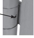
NON-REMOVABLE
Included with all 2 and 4 ball bearing, std and heavy weight hinges.
- PIN (NRP): Groove in pin accepts set screw in center barrel.
FRAME
• Set screw secured using a 3/32" hex (allen) wrench and is not accessible when door is closed.
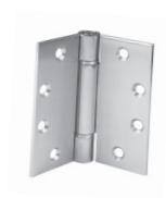
TYPE: • Full Mortise. Hinge leaves are mortised into the door and frame.

• Provides 1/16" of clearance between both leaves when the hinge is in the closed position.

Specifications
MATERIALS: • STEEL — Applications: Interior doors, non-corrosive environments.
• STAINLESS STEEL — Applications: Exterior, doors, corrosive environments
PACKAGING: • Qty of Hinges Per Individual Carton:
3ea for Plain, 2 Ball Bearing and 4 Ball Bearing Hinges
3ea for Spring Hinges 1ea for Electrified Hinges • Qty of Hinges Per Master Carton:
48ea for Plain, 2 Ball Bearing and 4 Ball Bearing Hinges
FASTENERS: • All hinges packed with Machine Screws (12-24 x 1/2" FHMS)
and Wood Screws (12 x 1-1/4" FHWS)
CERTIFICATIONS, • Conforms with the requirements of NFPA 80-2013, Section 6.4.3.1.
LISTINGS, COMPLIANCES: • Certified to ANSI/BHMA A156.1-2006:
— Grade 1, 4 Ball Bearing (HB) 2,500,000 cycles — Grade 2, 2 Ball Bearing (BB) 1,500,000 cycles — Grade 3, Plain Bearing (PL) 350,000 cycles
• UL 10C Listed:
— SH Series Spring Hinges
— EL Series Electrified Hinges
WARRANTY: • Five (5) year limited warranty

|
FULL MORTISE
HINGES |
DESCRIPTION |
FINISH
ANSI (US) |
PDQ HINGE MODEL |
|---|---|---|---|
| PLAIN B | EARING | ||
| 5 Knuckle | 600 (P) | 35 ST PL 4040 600 | |
| 0 H 0 |
Base Material: Steel with Steel Pin
Size: 4" x 4" |
652 (26D) | 35 ST PL 4040 652 |
|
Hinge Weight: Standard
Frequency of Use: Low Thickness: .130" 3 .005" ANSI 8133 |
|||
| 5 Knuckle | 600 (P) | 35 ST PL 4545 600 | |
| 9 4 9 |
Base Material: Steel with Steel Pin
Size: 4-1/2" x 4-1/2" |
613 (10B) | 35 ST PL 4545 613 |
| ° H ° | Hinge Weight: Standard | 619(US15) | 35 ST PL 4545 619 |
|
Frequency of Use: Low
Thickness: .130" 3 .005" |
652 (26D) | 35 ST PL 4545 652 | |
| ANSI 8133 | |||
| 2 BALL E | 25 CT DD 4540 C52 NDD | ||
| 5 Knuckle Base Material: Steel with Steel Pin Size: 4-1/2" x 4" Hinge Weight: Standard Frequency of Use: Medium Thickness: .134" 3 .005" ANSI A8112 | 652 (26D) | 35 ST BB 4540 652 NRP | |
| 5 Knuckle | 600 (P) | 35 ST BB 4545 600 NRP | |
| 0 9 9 | Base Material: Steel with Steel Pin | 605 (3) | 35 ST BB 4545 605 NRP |
|
Size: 4-1/2" x 4-1/2 "
Hinge Weight: Standard |
613 (10B) | 35 ST BB 4545 613 NRP | |
|
Frequency of Use: Medium
Thickness: .134"" 3 .005" |
619(US15) | 35 ST BB 4545 619 NRP | |
| ANSI A8112 | 652 (26D) | 35 ST BB 4545 652 NRP | |
| 5 Knuckle | 630 (32D) | 35 SS BB 4035 630 NRP | |
|
Base Material: Steel with Steel Pin
Size: 4" x 3-1/2" Hinge Weight: Standard Frequency of Use: Medium Thickness: .134" 3 .005" ANSI A5112 |
|||
| 5 Knuckle | 630 (32D) | 35 SS BB 4040 630 NRP | |
|
Base Material: Steel with Steel Pin
Size: 4" x 4" Hinge Weight: Standard Frequency of Use: Medium Thickness: .134" 3 .005" ANSI A5112 |
|||
| 5 Knuckle | 630 (32D) | 35 SS BB 4540 630 NRP | |
|
Base Material: Stainless Steel with Stainless
Steel Pin Size: 4-1/2" x 4" Hinge Weight: Standard Frequency of Use: Medium Thickness: .134" 3 .005" ANSI A5112 |
|||
|
5 Knuckle
Base Material: Stainless Steel with Stain- |
630 (32D) | 35 SS BB 4545 630 NRP | |
| less Steel Pin Size: 4-1/2" x 4-1/2" Hinge Weight: Standard Frequency of Use: Medium Thickness: .134" 3 .005" ANSI A5112 | |||
| 4 BALL E | BEARING | ||
| 5 Knuckle | 600 (P) | 35 ST HB 4545 600 NRP | |
|
Base Material: Steel with Steel Pin
Size: 4-1/2" x 4-1/2" |
605 (3) | 35 ST HB 4545 605 NRP | |
| Hinge Weight: Heavy | 613 (10B) | 35 ST HB 4545 613 NRP | |
| Frequency of Use: High Thickness: .180" 3 .005" | 619(US15) | 35 ST HB 4545 619 NRP | |
| ANSI 8111 | 652 (26D) | 35 ST HB 4545 652 NRP |
|
FULL MORTISE
HINGES |
DESCRIPTION |
FINISH
ANSI (US) |
PDQ HINGE MODEL |
|---|---|---|---|
| 4 BALL BE | ARING | ||
| 5 Knuckle Base Material: Steel with Steel Pin Size: 5" x 4-1/2" Hinge Weight: Heavy Frequency of Use: High Thickness: .180" 3 .005" ANSI 8111 | 652 (26D) | 35 ST HB 5045 652 NRP | |
| 5 Knuckle Base Material: Stainless Steel with Stainless Steel Pin Size: 4-1/2" x 4-1/2" Hinge Weight: Heavy Frequency of Use: High Thickness: .180" 3 .005" ANSI 5111 | 630 (32D) | 35 SS HB 4545 630 NRP | |
| 5 Knuckle Base Material: Stainless Steel with Stainless Steel Pin Size: 5" x 4-1/2" Hinge Weight: Heavy Frequency of Use: High Thickness: .180" 3 .005" ANSI 5111 | 630 (32D) | 35 SS HB 5045 630 NRP | |
| 5 Knuckle Base Material: Stainless Steel with Stainless Steel Pin Size: 5" x 5" Hinge Weight: Heavy Frequency of Use: High Thickness: .180" 3 .005" ANSI 5111 | 630 (32D) | 35 SS HB 5050 630 NRP |
| SPRING HINGES | DESCRIPTION |
FINISH
ANSI (US) |
PDQ HINGE MODEL |
|---|---|---|---|
| 3 Knuckle Base Material: Steel Size: 4-1/2" x 4-1/2" Hinge Weight: Standard Frequency of Use: Medium Thickness: .134" 3 .005" ANSI K8107-1F |
600 (P)
613 (10B) 619 (US15) 652 (26D) |
35 ST SH 4545 600
35 ST SH 4545 613 35 ST SH 4545 619 35 ST SH 4545 652 |
|
| 3 Knuckle Base Material: Stainless Stee LISTED Size: 4-1/2" x 4-1/2" Hinge Weight: Standard Frequency of Use: Medium Thickness: .134" 3 .005" ANSI K5107-1F | 630 (32D) | 35 SS SH 4545 630 |
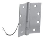
Electrified Hinges
| FEATURES |
OPTION
DESIGNATOR |
DESCRIPTION | |
|---|---|---|---|
| EL 2 | Concealed electric through-wire (2 wires, 22GA) | ||
| UL Fire | EL 4 | Concealed electric through-wire (4 wires, 28GA) | |
|
Listed for use with electrified
mortise or cylindrical locks, exit devices with electric latch |
EL 10 | Concealed electric through-wire (10 wires, 28GA) | |
|
retraction, electric strikes, locks
or exit devices with monitor ing or request to exit switches |
EL 24 |
Concealed electric through-wire
(2 wires @ 22GA, 4 wires @ 28GA) |
|
|
Electrical Specifications
Concealed electric through |
ELM 3 | Concealed electric monitor (3 wires, 28GA) | |
|
wire: 50 volts AC/DC @ 3.5
amps continuous, 16 amps pulse (maximum pulse width: |
ELM 4 |
Concealed electric through-wire and monitor
(4 through wires and 3 monitor wires, all 28GA) |
|
|
400msec., 10 sec minimum off
time between pulses) Concealed electric monitor: |
ELM 6 |
Concealed electric through-wire and monitor
(6 through wires and 3 monitor wires, all 28GA) |
|
| 30 VDC @ .5 amps | ELM 8 |
Concealed electric through-wire and monitor
(8 through wires and 3 monitor wires, all 28GA) |
How to Order
| QUANTITY | SERIES | MATERIAL | STYLE | SIZE | FINISH |
SECURITY
FEATURE2 |
ELECTRIFIED
OPTIONS1 |
|---|---|---|---|---|---|---|---|
| 10 | 35 | ST | BB | 4545 | 630 | NRP | — |
|
35 —
Full Mortise |
ST — Steel
SS — Stainless Steel |
PL — Plain
Bearing BB — 2 Ball Bearing HB — 4 Ball Bearing SH — Spring Hinge |
4035 —
4" X 3-1/2" 4040 — 4" X 4" 4540 — 4-1/2" X 4" 4545 — 4-1/2" X 4-1/2" 5045 — 5" x 4-1/2" 5050 — 5" x 5"" |
600 — Prime
Coated 605 — Bright Brass 613 — Oil Rub Bronze 619 — Satin Nickel 652 — Satin Chrome 630 — Satin Stainless Steel |
NRP — Non
Removable Pin |
EL 2 — Concealed electric
through-wire (2 wire, 22 ga) EL 4 — Concealed electric through-wire (4 wire, 28 ga) EL 10 — Concealed electric through-wire (10 wire, 28 ga) EL 24 — Concealed electric through-wire (2 wires @ 22 ga, 4 wires @ 28ga) ELM 3 — Concealed electric monitor (3 wire, 28 ga) ELM 4 — Concealed electric through-wire and monitor (4 through wires and 3 monitor wires, all 28GA) ELM 6 — Concealed electric through-wire and monitor (6 through wires and 3 monitor wires, all 28GA)3 ELM 8 — Concealed electric through-wire and monitor (8 through wires and 3 monitor wires, all 28GA)3 |
Ordering example: Plain bearing hinge: 35 ST PL 4545 600 4 Wire Std Weight Hinge: EL 4 35 SS BB 4545 630 NRP
Notes:
- 1- EL Series only available in 2 and 4 ball bearing. Includes NRP.
- 2 NRP only available in 2 and 4 ball bearing.
- 3 Not available in 4 ball bearing heavy weight hinges.
Accessories
| PART | DESCRIPTION |
|---|---|
| 85004 | MORTAR GUARD FOR ELECTRIFIED HINGES |
Quick Reference Guide
| Referen | ı | ı | ||||||||||||
|---|---|---|---|---|---|---|---|---|---|---|---|---|---|---|
| PDQ HINGE MODEL* |
FINISH
ANSI (US) |
ANSI
NUMBER* |
STYLE |
BASE
MATERIAL |
SIZE | FREQUENCY | WEIGHT | THICKNESS | SWAGING | |||||
| FU | JLL MORTISE | HINGES | ||||||||||||
| 35 ST PL 4040 600 | 600 (P) | 4" x 4" | ||||||||||||
| 35 ST PL 4040 626 | 652 (26D) | 4 × 4 | ||||||||||||
| 35 ST PL 4545 600 | 600 (P) | A8133 | PLAIN | LOW | .130"3.005" | |||||||||
| 35 ST PL 4545 613 | 613 (10B) | |||||||||||||
| 35 ST PL 4545 626 | 652 (26D) | STEEL | ||||||||||||
| 35 ST BB 4545 600 NRP | 600 (P) | SIEEL |
4-1/2" x
4-1/2" |
|||||||||||
| 35 ST BB 4545 605 NRP | 605 (3) | CTANDADD | ||||||||||||
| 35 ST BB 4545 613 NRP | 613 (10B) |
A8112
w/NRP |
STANDARD | |||||||||||
| 35 ST BB 4545 626 NRP | 652 (260) | .134"3.005" | 2 LEAVES | |||||||||||
| 35 ST BB 4540 626 NRP | 652 (26D) |
2 BALL
BEARING |
4-1/2 x 4" | MEDIUM | ||||||||||
| 35 SS BB 4035 630 NRP | 4" x 3-1/2" | |||||||||||||
| 35 SS BB 4040 630 NRP | 670 (700) | A5112 |
STAINLESS
STEEL |
4" x 4" | ||||||||||
| 35 SS BB 4540 630 NRP | 630 (32D) | w/NRP | 4-1/2 x 4" | |||||||||||
| 35 SS BB 4545 630 NRP | ||||||||||||||
| 35 ST HB 4545 600 NRP | 600 (P) | |||||||||||||
| 35 ST HB 4545 605 NRP | 605 (3) |
4-1/2" x
4-1/2" |
||||||||||||
| 35 ST HB 4545 613 NRP | 613 (10B) |
A8111
w/NRP |
STEEL | STEEL | HEAVO | 100" 2 005" | ||||||||
| 35 ST HB 4545 626 NRP | 652 (26D) | 4 BALL | ||||||||||||
| 36 ST HB 5045 626 NRP | 652 (260) | BEARING | 5" x 4-1/2" | HIGH | HEAVY | .180" 3.005" | ||||||||
| 35 SS HB 4545 630 NRP |
4-1/2" x
4-1/2" |
|||||||||||||
| 35 SS HB 5045 630 NRP | 630 (32D) |
A5111
w/NRP |
STAINLESS
STEEL |
5" x 4-1/2" | ||||||||||
| 35 SS HB 5050 630 NRP | 5" x 5" | |||||||||||||
| SPRING HIN | GES | |||||||||||||
| 35 ST SH 4545 613 | 613 (10B) | |||||||||||||
| 35 ST SH 4545 613 | 613 (10B) | K8107-1F | STEEL | 4-1/2" x | MEDIUM | STANDARD | .134+005 | 2 LEAVES | ||||||
| 35 ST SH 4545 626 | 652 (26D) | 4-1/2" | ||||||||||||
| 35 SS SH 4545 630 | 630(32D) | K5107-1F |
STAINLESS
STEEL |
|||||||||||
| ELECTRIFIED H | INGES |
Recommended Number of Hinges
On doors up to 5' (1.52m) use two hinges and an additional hinge for each additional 2.5' (.76m) or fraction thereof.
See table below:
| DOOR HEIGHT (UP TO) |
RECOMMENDED
# OF HINGES |
|
|---|---|---|
| FT | M | |
| 5 | 1.52 | 2 |
| 7-1/2 | 2.29 | 3 |
| 10 | 3.05 | 4 |
| 12-1/2 | 3.81 | 5 |
| 15 | 4.57 | 6 |
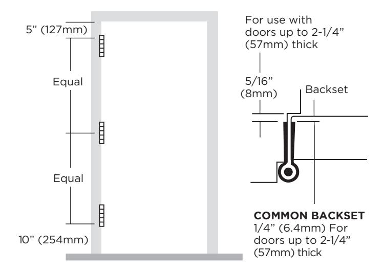
Hinge Locations on Door
- Top hinge 5" (127mm) from frame rabbet to top of hinge barrel.
- Bottom hinge 10" (254mm) from bottom edge of hinge barrel to finished floor.
- Center third hinge between top and bottom hinges.
NOTE: This information is for reference only. Actual placement may vary according to code requirements and guidelines provided by the door manufacturer..
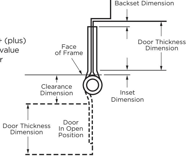
Hinge Width
|
DOOR THICKNESS
CLEARANCE REQUIRED |
WIDTH OF HINGE
IN OPEN POSITION |
||||
|---|---|---|---|---|---|
| INCHES | MM | INCHES | MM | INCHES | MM |
| 1-3/8" | 34.9 |
1-1/4"
1-3/4" |
31.8
44.5 |
3-1/2"
4" |
88.9
101.6 |
| 1-3/4" | 44.5 |
1"
1-1/2" 2" 3" |
25.4
38.1 50.8 76.2 |
4"
4-1/2" 5" 6" |
101.6
104.3 127 152.4 |
| 2" | 50.8 |
1"
1-1/2" 2-1/2" |
25.4
38.1 63.5 |
4-1/2"
5" 6" |
114.3
127 152.4 |
| 2-1/4" | 57.15 |
1"
2" |
25.4
50.8 |
5"
6" |
127
152.4 |
| 2-1/2" | 63.5 |
3/4"
1-3/4" |
19
44 |
5"
6" |
127
152.4 |
| 3" | 76.2 |
3/4"
2-3/4" 4-3/4" |
19
69.9 120.7 |
6"
8" 10" |
152.4
203.2 254 |
Hinge Width Formula
Calculation to determine hinge width requirements for extra clearance
Take thickness of door - (subtract) backset x (multiply) 2 + (plus) inset (if applicable) = (equals) hinge width. If the resulting value does not match a standard hinge width, use the next larger hinge (width).
Typical Door Weights
| DOOR THICKNESS | |||||||||
|---|---|---|---|---|---|---|---|---|---|
|
DOOR
MATERIAL |
INCHES
1-3/8" |
MM
34.9 |
INCHES
1-3/4" |
MM
44.5 |
INCHES
2" |
MM
50.8 |
|||
| lbs/ft2 | kg/m2 | lbs/ft2 | kg/m2 | lbs/ft2 | kg/m2 | ||||
| Ash | 4 | 19.5 | 5 | 24.4 | 6 | 29.3 | |||
| Birch | 4.25 | 20.8 | 5.5 | 26.9 | 6.25 | 30.5 | |||
| Fir | 3 | 14.6 | 3.5 | 17.1 | 4 | 19.5 | |||
| Mahogany | 3.5 | 17.1 | 4.5 | 22 | 5.25 | 25.6 | |||
| Oak | 5 | 24.4 | 7 | 34.2 | 8 | 39.1 | |||
| White Pine | 3 | 14.6 | 3.5 | 17.1 | 4 | 19.5 | |||
| Hollow Core | 2 | 9.8 | 2.5 | 12.2 | — | — | |||
| Particle Core | 4 | 19.5 | 5 | 24.4 | — | — | |||
| Solid Core | 3.5 | 17.1 | 4.5 | 22 | 5.25 | 25.6 | |||
| Kalamein | — | — | 5 | 24.4 | — | — | |||
| Mineral Core | 3.5 | 17.1 | 4 | 19.5 | — | — | |||
| Lead Lined Wood w/ 1/16" thick lead | — | — | 8.7 | 42.5 | — | — | |||
| Lead Lined Wood w/ 1/8" thick lead | — | — | 12.4 | 60.5 | — | — | |||
| Lead Lined Wood w/ 3/16" thick lead | — | — | 16.1 | 78.6 | — | — | |||
| Lead Lined Wood w/ 1/4" thick lead | — | — | 19.8 | 96.7 | — | — | |||
| Lead Lined Wood w/ 3/8" thick lead | — | — | 27.2 | 132.8 | — | — | |||
| Lead Lined Wood w/ 1/2" thick lead | — | — | 34.6 | 168.9 | — | — | |||
| Hollow Metal 18 gauge | 4.3 | 21 | 4.6 | 22.5 | — | — | |||
| Hollow Metal 16 gauge | 5.4 | 26.4 | 5.8 | 28.3 | — | — | |||
| Hollow Metal 15 gauge | 6.2 | 30.3 | 6.5 | 31.7 | — | — | |||
| Hollow Metal 14 gauge | 7 | 34.2 | 7.3 | 35.6 | — | — | |||
| Hollow Metal 13 gauge | 8.3 | 40.5 | 8.7 | 42.5 | — | — | |||
| Hollow Metal 12 gauge | 9.9 | 48.3 | 10.2 | 49.8 | — | — | |||
| Hollow Metal 11 gauge | 11.2 | 54.7 | 11.6 | 56.6 | — | — | |||
| Hollow Metal 10 gauge | 12.8 | 62.5 | 13 | 63.5 | — | — | |||
The above chart indicates approximate weights for common door types.
These estimations do not include the additional weight of any door hardware.

Hinge Selection for Labeled Fire Doors
Reproduced with Permission from NFPA 80-2010, Fire Doors and Other Opening Protectives, Copyright © 2009, National Fire Protection Association. This reprinted material is not the complete and official position of NFPA on the referenced subject, which is represented only by the standard in its entirety.
- 6.4.3* Builders Hardware.
- 6.4.3.1 Hinges. Hinges shall be as specified in individual door manufacturer's published listings or Table 6.4.3.1.
- 6.4.3.1.1 Doors up to 60 in. (1.52 m) in height shall be provided with two hinges and an additional hinge for each additional 30 in. (076 m) of door height or fraction thereof.
Table 6.4.3.1 Builders Hardware Mortise, Surface, and Full Length Hinges, Pivots, or Spring Hinges for Swinging Doors
|
DOOR
RATING (HR) |
MAXIMUM DOOR SIZE
WIDTH HEIGHT |
WIDTH |
MINIMUM HINGE SIZE
THICKNESS |
HINGE TYPE | ||
|---|---|---|---|---|---|---|
| FOR 1-3 ⁄4 IN. (44.5-MM) OR THICKER DOORS | ||||||
| 3 or Less | 4 ft. (1.22m) | 10 ft. (3.05m) | 4.5 in. (114.3mm) |
0.180 in.
(4.57mm) |
Steel, mortise or surface | |
| 3 or Less | 4 ft. (1.22m) | 8 ft. (2.44m) | 4.5 in. (114.3mm) |
0.134 in.
(3.40mm) |
Steel, mortise or surface | |
| 1-1/2 or Less | 3-1⁄6 ft. (0.96m) | 8 ft. (2.44m) | 6 in. (152.4mm) |
0.225 in.
(5.72mm) |
Steel, olive knuckle or paumelle | |
| 3 or Less | 4 ft. (1.22m) | 10 ft. (3.05m) | 4 in. (101.6mm) |
0.225 in.
(5.72mm) |
Steel pivots (including top,
bottom, and intermediate) |
|
| 1-1/2 or Less | 3 ft. (0.91m) | 5 ft. (1.52m) | 4 in. (101.6mm) |
0.130 in.
(3.30mm) |
Steel, mortise or surface | |
| 1-1/2 or Less | 2 ft. (0.61m) | 3 ft. (0.91m) | 3 in. (76.2mm) |
0.092 in.
(2.34mm) |
Steel, mortise or surface | |
| 3 or Less | 3 ft. (0.91m) | 7 ft. (2.13m) | 4.5 in. (114.3mm) |
0.134 in.
(3.40mm) |
Steel mortise or surface
(labeled, self closing, spring type) |
|
| 3 or Less | 3 ft. (0.91m) | 7 ft. (2.13m) | 4 in. (101.6mm) |
0.106 in.
(2.67mm) |
Steel mortise or surface
(labeled, self closing, spring type) |
|
| FOR 1-3 ⁄8 IN. (34.93-MM) OR THICKER DOORS | ||||||
| 3 or Less | 3 ft. (0.91m) | 7 ft. (2.13m) | 3.5 in. (88.9mm) | 0.123 in. (3.12mm) | Steel, mortise or surface | |
| 3 or Less | 2-2⁄3 ft. (0.81m) | 7 ft. (2.13m) | 3.5 in. (88.9mm) |
0.105 in.
(2.67mm) |
Steel mortise or surface
(labeled, self closing, spring type) |
|
- 6.4.3.1.1.1 The distance between hinges shall be permitted to exceed 30 in (0.76 m).
- 6.4.3.1.1.2 Where spring hinges are used, at least two shall be provided.
- 6.4.3.1.2 All hinges or pivots, except spring hinges, shall be of the ball bearing type.
- 6.4.3.1.2.1 Hinges or pivots employing other anti-friction bearing surfaces shall be permitted if they meet the requirements of ANSI/BHMA A156.1, Standard for Butts and Hinges.
- 6.4.3.1.2.2 Spring hinges shall be labeled and shall meet the requirements of ANSI/BHMA A156.17, Standard for Self Closing Hinges & Pivots, Grade 1.
- 6.4.3.1.3 Hinges 4 1/2 in. (114 mm) high and 0.180 in. (4.57 mm) thick shall be permitted for use on wide and heavy doors or doors that are subjected to heavy use or unusual stress.
Hinge Selection for Labeled Fire Doors (Cont.)
-
6.4.3.1.4 Fire doors with hinges of lighter weight that are not of the ball bearing type shall be permitted under the following conditions:
- 1. They are part of a listed assembly.
- 2. They meet the test requirements of ANSI/BHMA A156.1, Standard for Butts and Hinges.
- 3. They have been tested to a minimum of 350,000 cycles.
- 6.4.3.1.5 Pivot sets made up of components that are smaller or of a lighter gauge than shown in Table 6.4.3.1 shall be permitted to be used, provided they meet the requirements of ANSI/BHMA A156.4, Standard for Door Controls (Closers), and are in accordance with the manufacturer's label service procedures.
- 6.4.3.2 Attaching Hinges to Doors.
- 6.4.3.2.1 Hinges shall be secured in accordance with the listing and the manufacturer's installation instructions.
- 6.4.3.2.2 Mortise hinges shall be secured to reinforcements in the doors with steel machine screws.
- 6.4.3.2.3 Mortise hinges shall be secured to wood and plastic-covered composite doors or wood core doors with No. 12 x 1 1/4 in. (31.75 mm) flat, threaded-to-the-head, steel wood screws. Pilot holes shall be drilled that are 5/32 in. (4 mm) in diameter.
- 6.4.3.2.4 Surface hinges shall be attached with steel through-bolts.
- 6.4.3.3 Attaching Hinges to Frames. Hinges shall be secured to frames with steel screws.
- 6.4.3.3.1 Types of screws shall be permitted to vary depending on material use for the manufacture of labeled door frames.
- 6.4.3.3.2 The manufacturer's instructions and published listings for labeled door frames shall be referenced for specific screw requirements.
- 6.4.3.3.4 Shimming. When required to meet the clearances stated in 6.3.1.7, the shimming of hinges using steel shims shall be permitted.
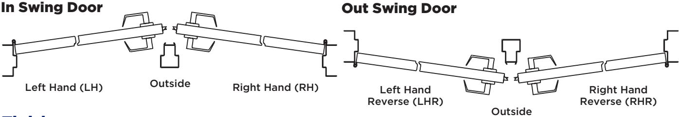
Handing
Finishes
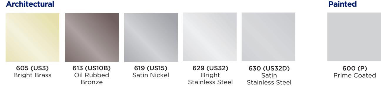

652 (US26D) Satin Chromium

Cross Reference
| HINGE DESCRIPTION | PDQ | ANSI | BOMMER | HAGER |
MCKIN
NEY |
PBB | STANLEY | |||
|---|---|---|---|---|---|---|---|---|---|---|
| 1279 | T2714 | |||||||||
| Plain Bearing, Standard Weight – Steel | 35STPL | A8133 | 5000 | EC1100 | MP79 | PB81 | F179 | |||
| BB1279 | TA2714 | |||||||||
| 2 Ball Bearing, Standard Weight – Steel | 35STBB | A8112 | BB5000 | ECBB1100 | MPB79 | BB81 | FBB179 | |||
| 2 Ball Bearing, Standard Weight – Stainless | BB1191 | TA2314 | ||||||||
| Steel | 35SSBB | S5112 | BB5002 | (630/32D) | (630/32D) | BB51 | FBB191 | |||
| BB1168 | T4A3786 | |||||||||
| 4 Ball Bearing, Heavy Weight – Steel | 35STHB | A8111 | BB5004 | ECBB1102 | MPB68 | 4B81 | FBB168 | |||
| 4 Ball Bearing, Heavy Weight – Stainless | BB1199 | T4A3386 | ||||||||
| Steel | 35SSHB | A5111 | BB5006 | ECBB1103 | MPB68 | 4B51 | FBB199 | |||
| 1250 | 1502 | |||||||||
| Spring Hinge, Self Closing – Steel | 35STSH | K8107-1F | LB4310C | EC1105 | MPS60 | SP81 | 2060R |
| Notes: | |
|---|---|

Phone: 800.441.9692
Tech Support: 833.2.PDQTEC (833.273.7832) FAX: 717.656.6892 | Email: help@pdqlocks.com
Headquarters: 2230 Embassy Drive, Lancaster, PA 17603
P.O. Box 6426, Lancaster, PA 17607
Regional Distribution Centers: Lancaster, PA | Norcross, GA, Kansas City, MO | Denver, CO | Henderson, NV | Auburn, WA
Design Office: Milan, Italy
pdqlocks.com