hager_780-045_HD_full_specs
Open the original PDF document
View PDF780-045-HD-95
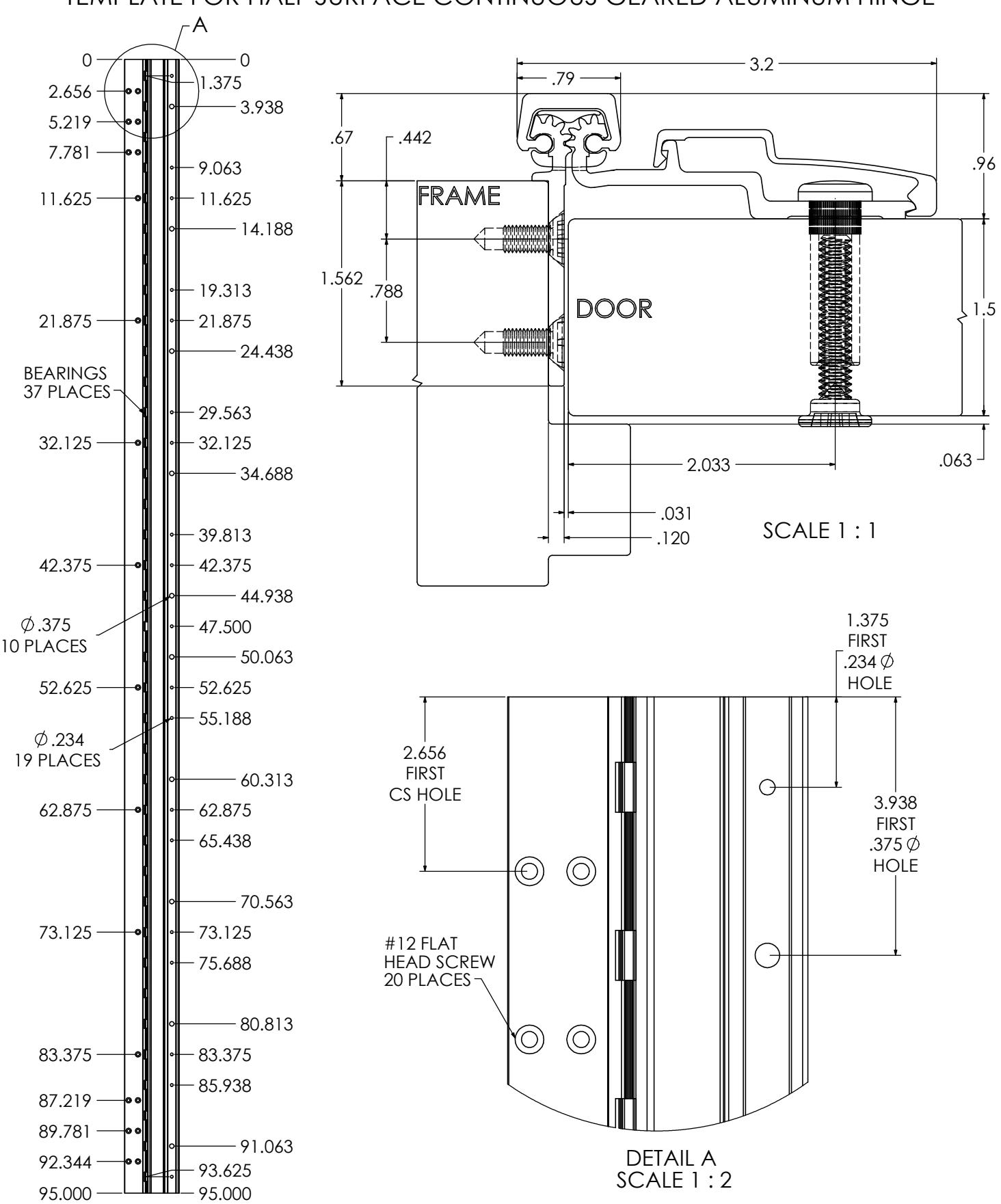
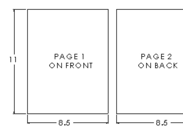
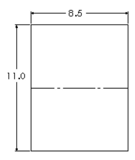
TEMPLATE FOR HALF SURFACE CONTINUOUS GEARED ALUMINUM HINGE
REVISION:
04/01/17

ROTON INSTRUCTION SHEET ROTON MODEL: 780-045, 780-046
HAGER Companies, 139 Victor Street, St. Louis, MO 63104 (800) 325-9995
PART NO: 75007045 REVISION: 05/16/16
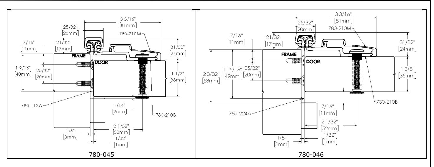
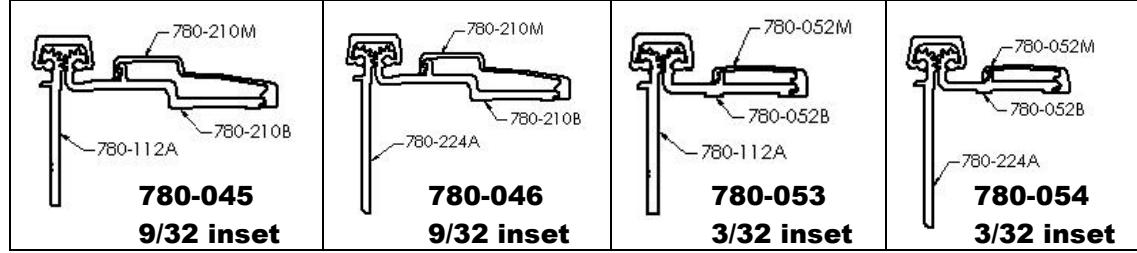
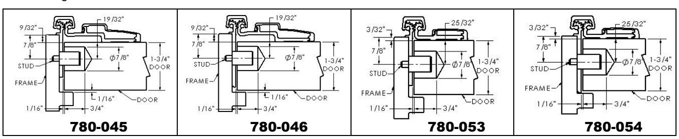
ROTON Model 780-045 and 780-046 are Aluminum Continuous Geared Half Surface Hinges that provides 9/32" door inset. These can be used for custom applications with thinner doors and/or non-standard frames. Minimum clearance between the hinge edge of the door and the frame is 5/32" (4mm). "HD" models have additional bearings for heavy-duty application.
Hinge Length
All ROTON Hinges are supplied approximately 1" shorter than the nominal door height to avoid threshold or carpet clearance problems. If the hinge must be trimmed shorter, first determine the correct hand of the door and orientation of the hinge. Then mark and trim from the bottom of the hinge only – do not cut from the top end.
|
Nom. Door
Height |
Nom. Hinge
Length |
NUMBER OF
FASTENERS (Frame/Door/) |
|---|---|---|
| 6'-8" | 79" (2006mm) | 15 / 25 |
| 7'-0" | 83" (2108mm) | 19 / 27 |
| 7'-2" | 85" (2159mm) | 19 / 27 |
| 8'-0" | 95" (2413mm) | 20 / 29 |
| 10'-0" | 119" (3022mm) | 23 / 35 |
Total Clearance Between Door And Frame Width
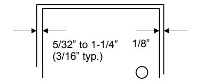
SINGLE DOOR
Hinge side clearance (typical) Latch side clearance (typical) TOTAL 3/16" (4.7mm) 1/8" (3.2mm) 5/16" (7.9mm)
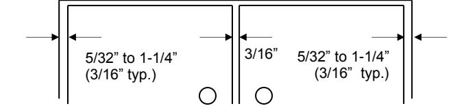
Pair of Doors
First hinge side clearance (typical) 3/16" Clearance between doors (typical) 3/16" Second hinge side clearance (typical) 3/16" TOTAL 7/16"
3/16" (4.7mm) 3/16" (4.7mm) 3/16" (4.7mm) 9/16" (14.1mm)
General Fitting Procedure
- <u>For new construction with metal doors/frames:</u> To accommodate the proper clearance between the door and frame, order the door undersized or the frame header oversized. See the clearance information above to attain the proper size. A minimum clearance of 5/32" (4.0mm) is required between the hinge edge of the door and the frame rabbet. Mortar guards, either Styrofoam or wood, are recommended for frames to prevent grout from interfering with the installation of the hinge fasteners.
- <u>For new site-hung wood doors:</u> If necessary, scribe and cut from the latch edge of the door to leave sufficient hinge stile thickness for proper fastening. See the clearance information above to attain the proper finished width of the door. A minimum clearance of 5/32" (4.0mm) is required between the hinge edge of the door and the frame rabbet.
- <u>For remodeling with existing wood or laminate doors:</u> If necessary, scribe and cut from the hinge edge of the door and plane smooth. See the clearance information above to attain the proper finished width of the door. A minimum clearance of 5/32" (4.0mm) is required between the hinge edge of the door and the frame.

ROTON INSTRUCTION SHEET PART NO: 75007045 ROTON MODEL: 780-045, 780-046 REVISION: 05/16/16
HAGER Companies, 139 Victor Street, St. Louis, MO 63104 (800) 325-9995
Installation Procedure
Frame Preparation
- 1. With the hinge open, place the hinge frame leaf against the frame rabbet making certain that the alignment rib is flush against the frame face along its entire length. (See Fig. 1) Position the top of the hinge 1/16" (1/8" maximum) below the header. Note: A 1/16" shim is recommended due to initial settling of the bearings.
- 2. Mark and center punch the screw hole locations. Accurate location is important for proper installation.
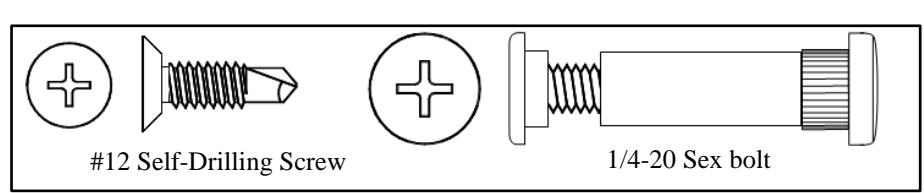
- 3. For metal frames 12 gage or less (≤ .110" /2.8mm), it is not necessary to pre-drill pilot holes if using the self-drilling screws provided. For metal frames thicker than 12 gage (>.110"/2.8mm), drill and tap all mounting holes for #12-24 threads prior to installing the screws. For wood frames, pre-drill pilot holes using a #18 (.170"/4.3mm) bit for optional #12 wood screws.
- 4. Attach the hinge to the frame rabbet. For metal frames, use the #12 self-drilling screws provided (recommended driver speed 1,900-2,500 RPM). For wood frames, use optional #12 wood screws.
Fig. 1
Door Preparation
- 1. Rotate the hinge leaf out of the way and set the door into the frame, using shims or wedges to adjust for the desired clearance on all sides.
- 2. Allow an additional 1/32" of clearance on the latch edge of the door at the top only. This will allow for any settling or twisting of the frame that may occur after the shims are removed and the weight of the door is transferred entirely to the frame.
- 3. Allow 1/16" clearance between the top of the door and the frame header rabbet. A good method for this is to use a 1/16" thick shim placed over the top edge of the door.
- 4. With the door held securely in place, rotate the hinge leaf into position on the face of the door.
-
5. (Standard sexbolt mounting) Mark and center punch the locations of the larger 3/8" diameter holes.
Accurate location is important for proper installation.
Rotate the hinge leaf back out of the way. At each mark, drill a hole completely through the door using a 3/8" (9.5mm) bit.
- (Optional mounting without sexbolts) Mark and center punch the locations of the smaller 15/64" diameter holes. For metal doors, use optional #12 self-drilling screws. For wood doors, pre-drill pilot holes using a #18 (.170"/4.5mm) bit for optional #12 wood screws.
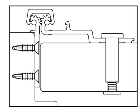
Fig. 2
Hanging the Door (See Fig. 2)
- 1. Attach the hinge to the door as shown. Sexbolts may be reversed if additional security is needed on the push face of the door, but once the molding is in place reversed sexbolts cannot be accessed for maintenance or removal.
- 2. Remove all shims and wedges and make a gentle trial swing. Carefully check the door for proper swing and clearance.
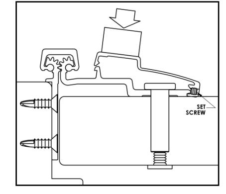
Install the Snap-On Molding (See Fig. 3)
1. For the door leaf – Locate and loosen the retaining setscrew on the edge of the molding with the 5/64" hex key provided. Hook the thicker leg of the molding under the outside edge of the door leaf along the full length of the hinge. Starting at the top and working downward, press or gently tap the opposite leg of the molding in place (if necessary use a rubber mallet or wood block under a hammer, taking care not to damage the molding). Tighten the retaining setscrew. Fig. 3

ROTON INSTRUCTION SHEET PART NO: 75007045 ROTON MODEL: 780-045, 780-046 REVISION: 05/16/16
HAGER Companies, 139 Victor Street, St. Louis, MO 63104 (800) 325-9995
|
—— 8 . 5 |
||
|---|---|---|
|
,
|
MANUAL AND | |
| 1.8 | n |

ROTON UL FIRE–RATED STUDS PART NO: 75006020 ROTON MODEL: 780-045, -046, -053, -054 REVISION: 05/31/17
HAGER Companies, 139 Victor Street, St. Louis, MO 63104 (800) 325-9995
ROTON Hinge U.L. Fire-Rated Studs – 780-045, -046, -053, -054
These instructions outline how to install the optional stainless steel studs (4) for ROTON Hinge models 780- 045, 780-046, 780-053 and 780-054. All four studs must be used in order to comply with U.L. requirements for composite wood fire doors rated up to 90 minutes and metal fire doors rated up to 3 hours.
Materials Needed
- Stainless steel studs (4).
- Drill, 7/8" diameter bit, #16 (.177") bit, 12-24 thread tap.
- #10 spanner screwdriver.
Installation
- 1. Install the hinge in accordance with the standard installation instructions furnished with the hinge.
- 2. On the frame leaf, drill tap 12-24 in the center of the four ¾" diameter holes.
- 3. On the door leaf, drill a 7/8" diameter by 3/4" deep is the horizontal location from the edge of the door. The horizontal location is the center line of the door minus the inset. The Vertical location is on the chart listed below. The first measurement is from the top of the hinge to the centerline of hole #1. The second, third and fourth holes are measured from centerline to centerline.
| Horizontal location | Location (for 1.75 door) |
|---|---|
| 780-045 and 046 | 19/32" |
| 780-053 and 054 | 25/32" |
| Vertical Location | 79" | 83" | 85" | 95" | 119" |
|---|---|---|---|---|---|
| Hole #1 | 13-7/8" | 15-7/8" | 16-7/8" | 16-3/4" | 13-3/8" |
| Hole #2 | 10-1/4" | 10-1/4" | 10-1/4" | 20-1/2" | 30-3/4" |
| Hole #3 | 30-3/4" | 30-3/4" | 30-3/4" | 20-1/2" | 30-3/4" |
| Hole #4 | 10-1/4" | 10-1/4" | 10-1/4" | 20-1/2" | 30-3/4" |
- 4. Insert a stud into each of the four #12-24 threaded holes on the frame and tighten securely using a #10 spanner screwdriver.
- 5. Close the door slowly to assure that the studs are properly aligned. Any minor interference can be corrected using a rat-tail file.

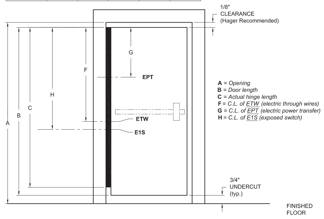
, RETW or K A B
locations for power transfer cutouts. All standard location dimensions the power transfer cutout. Please specify handing. For ease of ordering, Hager Companies has established standard are referenced from the top edge of the door to the centerline of
NOTE: These locations are for concealed hinges only.
| Opening | Door Height |
Actual Hinge
Length |
EMN | ETM | ETW | EPT | E1S | E | RETW | |
|---|---|---|---|---|---|---|---|---|---|---|
| 79 SD | 80" | 79-1/8" | 79" | 40-3/4" | 42-3/4" | 40-3/4" | 34-3/8" | 42-1/2" | 42-1/2" | – |
| 79 HD | 80" | 79-1/8" | 79" | 40-3/4" | 43-3/8" | 40-3/4" | 34-3/8" | 42-1/2" | 42-1/2" | 43-3/8" |
| 83 SD | 84" | 83-1/8" | 83" | 45-5/16" | 44-3/4" | 45-5/16" | 36-3/8" | 46-1/2" | 46-1/2" | – |
| 83 HD | 84" | 83-1/8" | 83" | 45-5/16" | 45-3/8" | 45-5/16" | 36-3/8" | 46-1/2" | 46-1/2" | 45-3/8" |
| 85 SD | 86" | 85-1/8" | N/A | N/A | N/A | N/A | N/A | N/A | N/A | N/A |
| 85 HD | 86" | 85-1/8" | 85" | 46-5/16" | 46-3/8" | 46-5/16" | 37-3/8" | 48-1/2" | 48-1/2" | 46-3/8" |
| 95 SD | 96" | 95-1/8" | 95" | 56-3/8" | 55-13/16" | 56-3/8" | 47-1/2" | 59-3/4" | 59-3/4" | – |
| 95 HD | 96" | 95-1/8" | 95" | 56-3/8" | 56-1/2" | 56-3/8" | 47-1/2" | 59-3/4" | 59-3/4" | 56-1/2" |
| 119 SD | 120" | 119-1/8" | N/A | N/A | N/A | N/A | N/A | N/A | N/A | N/A |
| 119 HD | 120" | 119-1/8" | 119" | 81-1/4" | 81-5/16" | 81-1/4" | 72-5/16" | 83-3/4" | 83-3/4" | 81-5/16" |
SD = Standard Duty HD = Heavy Duty

|
Von Duprin EPT 2 or EPT 10
wer Transfer Preparation Po |
Exposed Electric Contacts |
witches
Exposed Electric S |
Wire
Concealed Electric Through- |
Monitoring
Concealed Electric |
Wire
Concealed Electric Through- Monitoring and |
Wire
movable Electric Through- Re |
|
|---|---|---|---|---|---|---|---|
| Part Number | EPT | E | E1S | ETW | EMN | ETM | RETW |
| 780-045HD | • | ||||||
| 780-046HD | • | ||||||
| 780-053 | • | ||||||
| 780-053HD | • | ||||||
| 780-054HD | • | ||||||
| 780-110HD | • | ||||||
| 780-057 | • | • | |||||
| 780-111 | • | • | • | • | • | • | |
| 780-111HD | • | • | • | • | • | • | • |
| 780-111LL | • | • | • | • | • | • | |
| 780-112 | • | • | • | • | • | • | |
| 780-112HD | • | • | • | • | • | • | • |
| 780-112LL | • | • | • | • | • | • | |
| 780-124HD |
•
• |
•
• |
•
• |
•
• |
•
• |
•
• |
• |
| 780-124LL | • | • | |||||
|
780-157
780-224 |
• | • | • | • | • | • | |
| 780-224HD | • | • | • | • | • | • | • |
| 780-224LL | • | • | • | • | • | • | |
| 780-226HD | • | • | • | • | • | • | • |
| 780-226LL | • | • | • | • | • | • | |
| 780-235HD | • | ||||||
| 1200-600 | • | • | |||||
| 1200-650 | • | • | |||||
MODIFICATIONS & ADDITIONS
Special Cover Channels
Rounded back cover channels may be ordered. Availability for hinges with electrical modifications vary. Please consult the St. Louis sales office for confirmation.
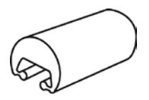
Round Back
Round Back Cover Channels
Clear Anodized
79", Sizes:
Bronze Anodized
Sizes: 79", 83", 85", 95", 119"
Black Anodized
Sizes: 79", 83", 85", 95", 119"
Note: Special cover channels available in clear, dark bronze and black finish.
|
Roton Cover Channel
Compatibility |
||
|---|---|---|
|
Hinge
Model |
FBCC
Flat |
Round
RBCC |
| 750-134 | • | • |
| 750-138 | • | • |
| 780-041 | • | • |
| 780-045 | • | • |
| 780-046 | • | • |
| 780-053 | • | • |
| 780-054 | • | • |
| 780-057 | • | • |
| 780-110 | • | • |
| 780-111 | • | • |
| 780-112 | • | • |
| 780-113 | • | • |
| 780-124 | • | • |
| 780-155 | • | • |
| 780-157 | • | |
| 780-210 | • | • |
| 780-211 | • | • |
| 780-213 | • | • |
| 780-224 | • | • |
| 780-226 | • | • |
| 780-235 | • | • |
| 780-257 | • | |
| 780-300 | • |
* Round back (RBCC) is not compatible with molded Hospital Tip option.


, RETW or K A B
locations for power transfer cutouts. All standard location dimensions the power transfer cutout. Please specify handing. For ease of ordering, Hager Companies has established standard are referenced from the top edge of the door to the centerline of
NOTE: These locations are for concealed hinges only.
| Opening | Door Height |
Actual Hinge
Length |
EMN | ETM | ETW | EPT | E1S | E | RETW | |
|---|---|---|---|---|---|---|---|---|---|---|
| 79 SD | 80" | 79-1/8" | 79" | 40-3/4" | 42-3/4" | 40-3/4" | 34-3/8" | 42-1/2" | 42-1/2" | – |
| 79 HD | 80" | 79-1/8" | 79" | 40-3/4" | 43-3/8" | 40-3/4" | 34-3/8" | 42-1/2" | 42-1/2" | 43-3/8" |
| 83 SD | 84" | 83-1/8" | 83" | 45-5/16" | 44-3/4" | 45-5/16" | 36-3/8" | 46-1/2" | 46-1/2" | – |
| 83 HD | 84" | 83-1/8" | 83" | 45-5/16" | 45-3/8" | 45-5/16" | 36-3/8" | 46-1/2" | 46-1/2" | 45-3/8" |
| 85 SD | 86" | 85-1/8" | N/A | N/A | N/A | N/A | N/A | N/A | N/A | N/A |
| 85 HD | 86" | 85-1/8" | 85" | 46-5/16" | 46-3/8" | 46-5/16" | 37-3/8" | 48-1/2" | 48-1/2" | 46-3/8" |
| 95 SD | 96" | 95-1/8" | 95" | 56-3/8" | 55-13/16" | 56-3/8" | 47-1/2" | 59-3/4" | 59-3/4" | – |
| 95 HD | 96" | 95-1/8" | 95" | 56-3/8" | 56-1/2" | 56-3/8" | 47-1/2" | 59-3/4" | 59-3/4" | 56-1/2" |
| 119 SD | 120" | 119-1/8" | N/A | N/A | N/A | N/A | N/A | N/A | N/A | N/A |
| 119 HD | 120" | 119-1/8" | 119" | 81-1/4" | 81-5/16" | 81-1/4" | 72-5/16" | 83-3/4" | 83-3/4" | 81-5/16" |
SD = Standard Duty HD = Heavy Duty

|
Von Duprin EPT 2 or EPT 10
wer Transfer Preparation Po |
Exposed Electric Contacts |
witches
Exposed Electric S |
Wire
Concealed Electric Through- |
Monitoring
Concealed Electric |
Wire
Concealed Electric Through- Monitoring and |
Wire
movable Electric Through- Re |
|
|---|---|---|---|---|---|---|---|
| Part Number | EPT | E | E1S | ETW | EMN | ETM | RETW |
| 780-045HD | • | ||||||
| 780-046HD | • | ||||||
| 780-053 | • | ||||||
| 780-053HD | • | ||||||
| 780-054HD | • | ||||||
| 780-110HD | • | ||||||
| 780-057 | • | • | |||||
| 780-111 | • | • | • | • | • | • | |
| 780-111HD | • | • | • | • | • | • | • |
| 780-111LL | • | • | • | • | • | • | |
| 780-112 | • | • | • | • | • | • | |
| 780-112HD | • | • | • | • | • | • | • |
| 780-112LL | • | • | • | • | • | • | |
| 780-124HD |
•
• |
•
• |
•
• |
•
• |
•
• |
•
• |
• |
| 780-124LL | • | • | |||||
|
780-157
780-224 |
• | • | • | • | • | • | |
| 780-224HD | • | • | • | • | • | • | • |
| 780-224LL | • | • | • | • | • | • | |
| 780-226HD | • | • | • | • | • | • | • |
| 780-226LL | • | • | • | • | • | • | |
| 780-235HD | • | ||||||
| 1200-600 | • | • | |||||
| 1200-650 | • | • | |||||

STANDARD LOCATIONS FOR ALL STAINLESS STEEL CONTINUOUS ELECTRICAL MODIFICATIONS
| 79" | 83" | 85" | 95" | 119" | |
|---|---|---|---|---|---|
| Opening | 80" | 84" | 86" | 96" | 120" |
| Door Height | 79-1/8" | 83-1/8" | 85-1/8" | 95-1/8" | 119-1/8" |
| Hinge Length | 79-3/16" | 83-1/8" | 85-1/8" | 95" | 118-3/4" |
| ETW | 41-1/2" | 43-1/2" | 45-1/2" | 55-3/8" | 79-1/8" |
| EPT | 24-1/2" | 28-7/16" | 30-7/16" | 40-1/2" | 64-7/16" |
| E1S | 41-1/2" | 43-1/2" | 45-1/2" | 55-3/8" | 79-1/8" |