
ROTON UL FIRE–RATED STUDS PART NO: 75006111
ROTON MODEL: 780-111, -112, -124, -224, -226, -235 REVISION: 05/31/17 HAGER Companies, 139 Victor Street, St. Louis, MO 63104 (800) 325-9995
ROTON Hinge U.L. Fire-Rated Studs – 780-111, -112, -124, -224, - 226, -235
These instructions outline how to install the optional stainless steel studs (4) for ROTON Hinge models 780- 112, 780-124 and 780-224. All four studs must be used in order to comply with U.L. requirements for composite wood fire doors rated up to 90 minutes and metal fire doors rated up to 3 hours.
Materials Needed
- Stainless steel studs (4).
- Drill, 3/4" diameter bit, #16 (.177") bit, 12-24 thread tap.
- #10 spanner screwdriver.
| Vertical Location | 79" | 83" | 85" | 95" | 119" |
|---|---|---|---|---|---|
| Hole #1 | 13-7/8" | 15-7/8" | 16-7/8" | 16-3/4" | 13-3/8" |
| Hole #2 | 10-1/4" | 10-1/4" | 10-1/4" | 20-1/2" | 30-3/4" |
| Hole #3 | 30-3/4" | 30-3/4" | 30-3/4" | 20-1/2" | 30-3/4" |
| Hole #4 | 10-1/4" | 10-1/4" | 10-1/4" | 20-1/2" | 30-3/4" |
Installation
- 1. Install the hinge in accordance with the standard installation instructions furnished with the hinge.
- 2. At the center of each 3/4" diameter pre-drilled hole in the frame leaf , drill and tap a #12-24 threaded hole into the frame (four places).
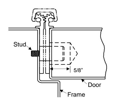
- 3. At each 3/4" diameter pre-drilled hole in the door leaf , drill a 3/4" diameter x 5/8" deep hole into the edge of the door (four places).
- 4. Insert a stud into each of the four #12-24 threaded holes of the frame and tighten securely using a #10 spanner screwdriver.
- 5. Close the door slowly to assure that the studs are properly aligned. Any minor interference can be corrected using a rat-tail file.

HAGER Companies, 139 Victor Street, St. Louis, MO 63104 (800) 325-9995
ROTON INSTRUCTION SHEET PART NO: 75007112 ROTON MODEL: 780-111, 780-112, 780-226, 780-235 REVISION: 05/16/16
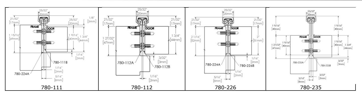
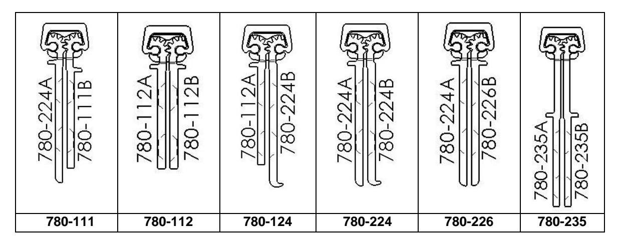
ROTON Models 780-111, 780-112, 780-226 and 780-235 are Aluminum Continuous Geared Concealed Leaf Hinges. Model 780- 111 provides a 1/8" door inset. The others accommodate flush doors. Each can be used with any standard frame without hinge preps, and either with or without reinforcements depending on door weight. Clearance required between the hinge edge of the door and the frame rabbet is 5/16" (7.9mm) minimum. For 780-235 allow for an additional 1/32" to lock side clearance. "HD" models have additional bearings for heavy-duty application. The 780-226 is intended for doors 2" or thicker.
Hinge Length
All ROTON Hinges are supplied approximately 1" shorter than the nominal door height to avoid threshold or carpet clearance problems. If the hinge must be trimmed shorter, first determine the correct hand of the door and orientation of the hinge. Then mark and trim from the bottom of the hinge only – do not cut from the top end.
| NOM. | NOM. HINGE | NUMBER OF |
| DOOR | LENGTH | FASTENERS |
| HEIGHT | (FRAME / | |
| DOOR | ||
| 6' 8" | 79" (2006mm) | 15 / 15 |
| 7' 0" | 83" (2108mm) | 19 / 19 |
| 7' 2" | 85" (2159mm) | 19 / 19 |
| 8' 0" | 95" (2413mm) | 20 / 20 |
| 10' 0" | 119" (3022mm) | 23 / 23 |
Total Clearance Between Door And Frame Width
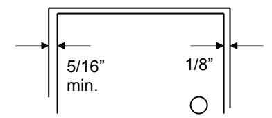
| SINGLE DOOR - SQUARE EDGED | |||
|---|---|---|---|
| Hinge thickness | 5/16" (7.9mm) | ||
| Allowance for frame irregularities | 1/32" (0.8mm) | ||
| Latch side clearance (typical) |
1/8"
(3.2mm) |
||
| TOTAL* | 15/32" (11.9mm) | ||
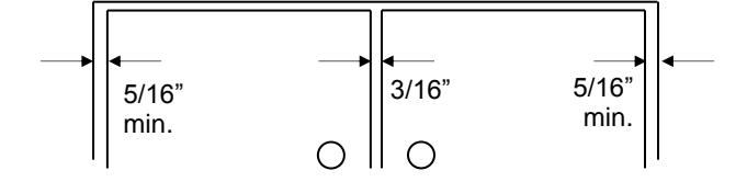
PAIR OF DOORS - SQUARE EDGED
| First hinge thickness | 5/16" (7.9mm) |
| First allowance for frame irregularities | 1/32" (0.8mm) |
| Clearance between doors (typical) | 3/16" (4.8mm) |
| Second hinge thickness | 5/16" (7.9mm) |
| Second allowance for frame irregularities | 1/32" (0.8mm) |
| TOTAL* | 7/8" (22.2mm) |
* For doors that are pre-beveled 1/8"-in-2" on the hinge edge, add 1/32" (0.8mm) per door to the TOTAL clearance shown. (780-235 hinges are not recommended for beveled doors) For 780-235 allow for an additional 1/32" to lock side clearance.
General Fitting Procedure
- For new construction with metal doors/frames: To accommodate the 5/16" (7.9mm) hinge clearance required for these ROTON models, order the door undersized or the frame header oversized. See the clearance information above to attain the proper size. Mortar guards, either Styrofoam or wood, are recommended for frames to prevent grout from interfering with the installation of the hinge fasteners.
- For new site-hung wood doors: If necessary, scribe and cut from the latch edge of the door to leave sufficient hinge stile thickness for proper fastening. A minimum clearance of 5/16" (7.9mm) is required between the hinge edge of the door and the frame rabbet. See the clearance information above to attain the proper finished width of the door.
- For remodeling with existing wood or laminate doors: If necessary, scribe and cut from the hinge edge of the door and plane smooth. A minimum clearance of 5/16" (7.9mm) is required between the hinge edge of the door and the frame rabbet. See the clearance information above to attain the proper finished width of the door.

ROTON INSTRUCTION SHEET
ROTON MODEL: 780-111, 780-112, 780-226, 780-235 HAGER Companies, 139 Victor Street, St. Louis, MO 63104 (800) 325-9995
PART NO: 75007112 REVISION: 05/16/16
Installation Procedure
Frame Preparation
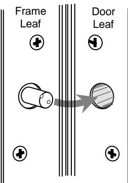
- With the hinge open, place the hinge frame leaf against the frame rabbet making certain that the alignment rib is flush against the frame face along its entire length. Position the top of the hinge 1/16" (1/8" maximum) below the header. Note: A 1/16" shim is recommended due to initial settling of the bearings. (See Fig. 1)
- 2. Mark and center punch the screw hole locations. Accurate location is important for proper installation.
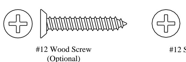
- 3. For metal frames 12 gage or less (≤ .110"/2.8mm), it is not necessary to pre-drill pilot holes if using the self-drilling screws provided. For metal frames thicker than 12 gage (> .110"/2.8mm), drill and tap all mounting holes for #12-24 threads prior to installing the screws. For wood frames, pre-drill pilot holes using a #18 (.170"/4.3mm) bit for optional #12 wood screws.
- 4. Do not attach the hinge to the frame at this time.
Door Preparation
- 1. With the hinge open, place the hinge door leaf against the edge of the door making certain that the door alignment rib is flush against the door face along its entire length (See Fig. 2). Position the top of the hinge flush with the top of the door.
- 2. Mark and center punch the screw hole locations. Accurate location is important for proper installation.
- 3. For hollow metal doors 12 gage or less (≤ .110"/2.8mm), it is not necessary to pre-drill pilot holes if using the self-drilling screws provided. For metal doors thicker than 12 gage (> .110"/2.8mm), drill and tap all mounting holes for #12-24 threads prior to installing the screws. For wood doors, pre-drill pilot holes using a #18 (.170"/4.3mm) bit for optional #12 wood screws (provided with LL models).
- Attach the hinge to the door. For metal doors, use the #12 self-drilling screws provided (recommended driver speed 1,900-2,500 RPM). For wood doors, use optional #12 wood screws.
Hanging the Door
- Position the door (with hinge attached) at 90° to the frame. Attach the hinge to the frame rabbet (See Fig. 3). For metal frames, use the #12 self-drilling screws provided (recommended driver speed 1,900-2,500 RPM). For wood frames, use optional #12 wood screws.
- 2. Make a gentle trial swing. Carefully check the door for proper swing and clearance.
Adjusting the Door
-
If lateral adjustment of the door is required due to excessive or uneven door/frame clearance, adjust by shimming where needed:
- For minor adjustments, an effective shimming material is 1-1/2" cloth duct tape. Apply the tape in stepped layers underneath the frame leaf where needed to build up to the desired thickness.
- b) To shift the entire door, a thin continuous aluminum strip may be used underneath the frame leaf (available in 1/16" (1.6mm) and 1/8" (3.2mm) thicknesses from HAGER).
- Retighten all screws. Carefully check the door for proper swing and clearance.
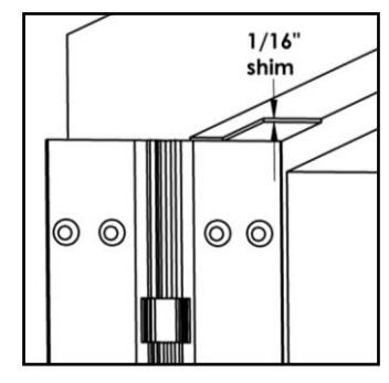
Fig. 1
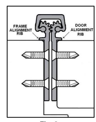
Fig. 2
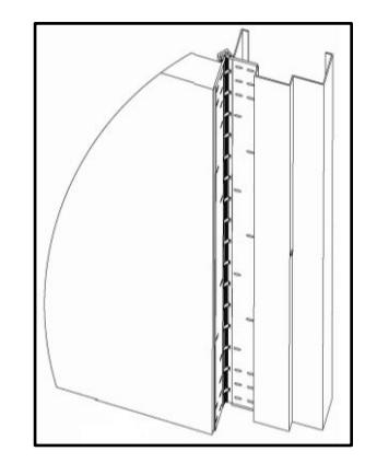
Fig. 3

ROTON INSTRUCTION SHEET PART NO: 75007112
ROTON MODEL: 780-111, 780-112, 780-226, 780-235 REVISION: 05/16/16 HAGER Companies, 139 Victor Street, St. Louis, MO 63104 (800) 325-9995

|
—— 8 . 5 |
||
|---|---|---|
| , • | MACHINE MICHIEF | name. |
| 1.8 | 7.7EV |
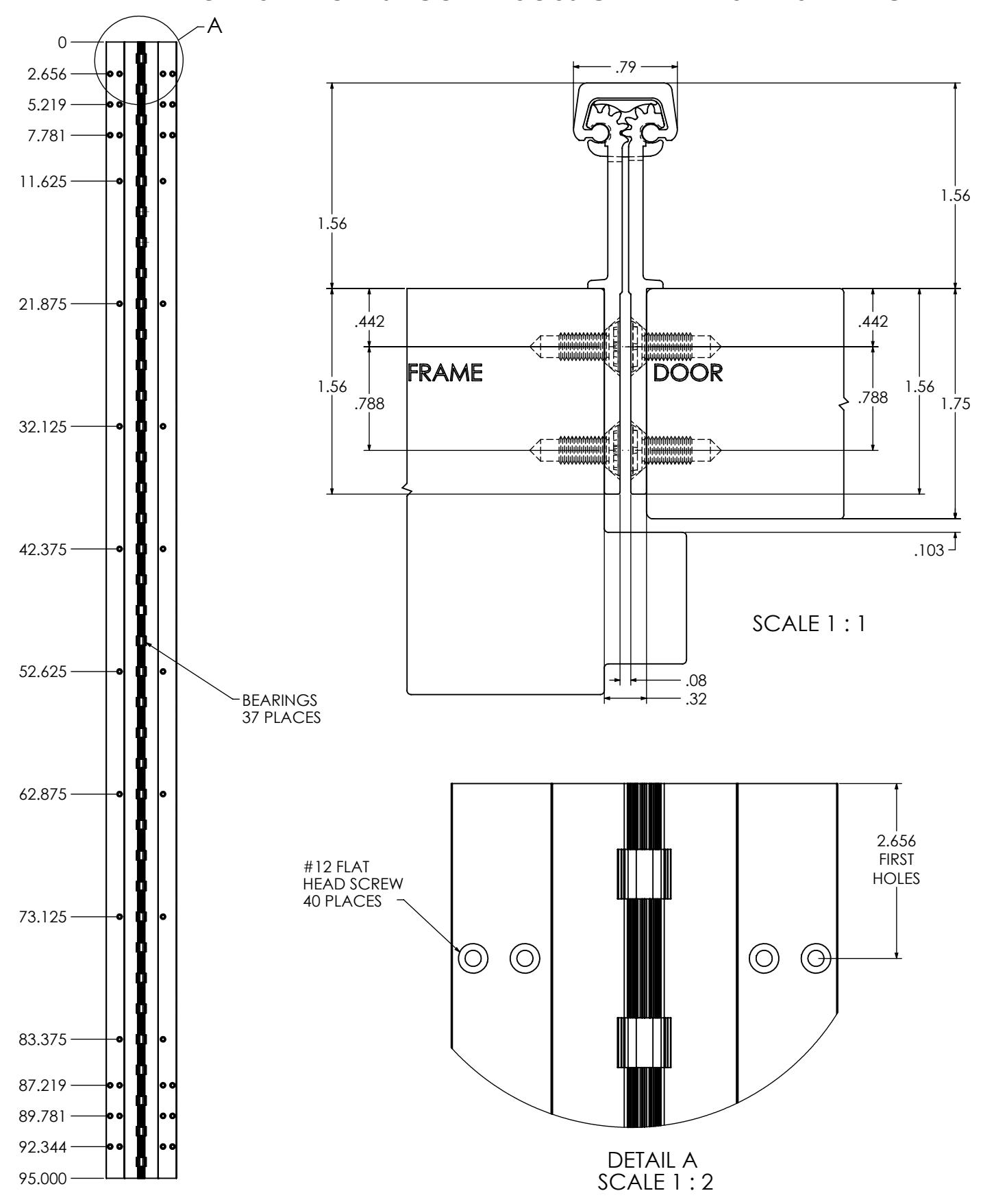
780-235-HD-95
REVISION: 04/22/16
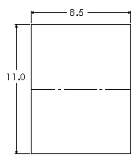
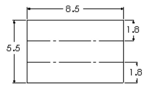
TEMPLATE FOR FULL MORTISE CONTINUOUS GEARED ALUMINUM HINGE
MODIFICATIONS & ADDITIONS
Special Cover Channels
Rounded back cover channels may be ordered. Availability for hinges with electrical modifications vary. Please consult the St. Louis sales office for confirmation.
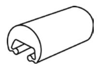
Round Back
Round Back Cover Channels
Clear Anodized
79", Sizes:
Bronze Anodized
Sizes: 79", 83", 85", 95", 119"
Black Anodized
Sizes: 79", 83", 85", 95", 119"
Note: Special cover channels available in clear, dark bronze and black finish.
|
Roton Cover Channel
Compatibility |
|||
|---|---|---|---|
|
Hinge
Model |
FBCC
Flat |
Round
RBCC |
|
| 750-134 | • | • | |
| 750-138 | • | • | |
| 780-041 | • | • | |
| 780-045 | • | • | |
| 780-046 | • | • | |
| 780-053 | • | • | |
| 780-054 | • | • | |
| 780-057 | • | • | |
| 780-110 | • | • | |
| 780-111 | • | • | |
| 780-112 | • | • | |
| 780-113 | • | • | |
| 780-124 | • | • | |
| 780-155 | • | • | |
| 780-157 | • | ||
| 780-210 | • | • | |
| 780-211 | • | • | |
| 780-213 | • | • | |
| 780-224 | • | • | |
| 780-226 | • | • | |
| 780-235 | • | • | |
| 780-257 | • | ||
| 780-300 | • | ||
* Round back (RBCC) is not compatible with molded Hospital Tip option.