gitcon-model-g50-installation-guide-for-swing-and-roll-up-doors.pdf_638406
Open the original PDF document
View PDF

Gitcon Model G50
for Swing & Roll-Up Doors
installation guide
Symbol Definitions

WARNINGS: Hazards or unsafe practices which could result in personal injury or product or property damage.

NOTES: contain important information and useful tips on the operation of your equipment.
For assistance during installation, call Technical Support at (800) 950-4744.
Basic Tools and Materials Required
- Pop rivet gun
- Electric hand drill
- 10mm (3/8") drill bit (standard doors) 14mm (17/32") drill bit (hollow doors)
-
Appropriate sized drill bit for drilling rivet head on handle (if rivet IS NOT stainless steel)
- Hand held power grinder (if rivet IS stainless steel)
- Tape
- Center punch
- Adjustable open end wrench or appropriate sized sockets/box wrenches
- Level
- Hacksaw
- Hammer
Before Drilling

Before drilling any holes, ensure that:
- You are wearing suitable eye protection.
- Adequate protection is fitted around the surrounding area to protect such things as cables, water/air pipes etc, from damage.
Before starting any work, determine the position the G50 is to be located, bearing in mind the following points:
- Ensure there is no obstruction on the inside of the door.
- Ensure the vehicle is parked on flat, level ground when installing this lock.
- Please remember you are installing a high quality, precision lock to a door which, even when new, will have a fair amount of free play in its operation. This free play will only increase with wear as the vehicle is used; therefore, great care must be taken during installation.
Remove Existing Handle
Note: Use a center punch to mark the rivet head before attempting to drill the head off. This will help prevent the likelihood of the drill slipping and damaging the vehicle door. If the rivet is stainless steel, a power grinder may be required to grind off the rivet head.
1. Grind or drill just enough to remove the rivet head and to avoid damaging the door. Once the head has been ground or drilled off, knock the remains of the rivet out using an appropriate sized punch. Remove the handle from the door. (See Figure 1.)
Note: Roll-up doors will have multiple rivets that need to be removed. (See Figure 2.)
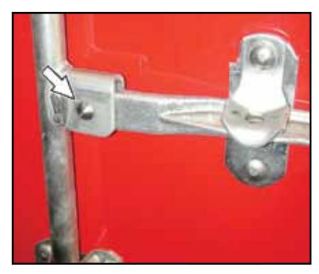
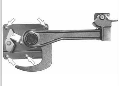
Figure 1 - Swing Door Figure 2 - Roll-Up Door
Remove Handle Retainer or Keeper Assembly
- 1. Drill/grind the bolts out of the handle retainer assembly (for swing door) or the handle keeper (for roll-up door). (See Figure 3 for Swing Door and Figure 4 for Roll-Up Door.)
- 2.Remove the retainer or keeper assembly.
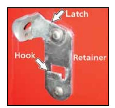
Figure 3 - Swing Door
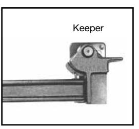
Figure 4 - Roll-Up Door
Install Handle
Swing Door
- 1. Attach the G50 handle to the hub where the old handle was removed, using the pin included in the kit. Insert the pin from the front.
- 2. Gain access to the rear of the pin and insert the rivet included in the kit and a washer on the rivet. Secure the rivet in position using pop rivet gun.

Note: If installing on a door with double vertical locking bars, install on the locking bar closest to the hinges.
Roll-Up Door
- 1. With the door closed, align the door handle assembly "J" hook with the center pin/plate of the latch box. Operate handle (open/close) to ensure correct position within the latch box.
- 2. Ensure the handle is level. Use the flat end of the handle. (See Figure 5.)
- 3. Using the handle assembly mounting bracket as a template, mark (center punch) the location of the mounting holes.
Standard Doors
- 4a. Drill the handle assembly mounting holes using an 8mm (5/16") drill bit.
- 5a. Insert and seat carriage bolts into supplied handle assembly. Seat carriage bolts by using a hammer to drive the bolts into the mounting plate.
- 6a. Mount handle assembly to door and secure from the inside with washer/lock washer/nuts provided.
Hollow Doors
- 4b. Drill the handle assembly mounting holes using a 14mm (7/16") drill bit.
- 5b. Insert ribbed neck carriage bolt into handle assembly. Place nylon spacers onto the carriage bolts.
- 6b. Mount handle assembly to door and secure from the inside with backplate, washers and nuts provided.

Note: If necessary, use a hacksaw to remove excess bolt length.
Install Lock Body
- 1. Using the new handle, close the door fully, ensuring correct shutting for closed position.
- 2. Ensure that the handle is level. Use flat on end of handle. (See Figure 5.)
- 3. Align template relative to the locking pin on the handle. (See Figure 5.)
- 4. Use tape to secure the template to the door.
- 5. Place the lock body over the coordinating location on the template and rotate the handle to ensure that it
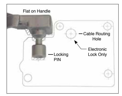
Figure 5 - Align Template to Handle
clears the lock body. If not, readjust the template.
Note: If the handle becomes locked in position, refer to the operational check on the following page to unlock and lift the handle.
- 6. Center punch all four mounting holes.
- 7. Remove the template.
Standard Doors
- 8a. Drill the four outside lock case mounting holes using a 10mm (3/8") drill bit.
- 9a. Start to mount the G50 body from the inside of the door using two of the 8mm lock body mounting bolts, two lock washers, and two flat washers. Attach through the upper right and lower left corners of the lock body mounting holes. (See Figure 6.)
Hollow Doors
- 8b. Drill the four outside lock case mounting holes using a 14mm (7/16") drill bit.
- 9b. Start to mount the G50 body from the inside of the door using two of the 8mm lock body mounting bolts, two lock washers, two flat washers, nylon spacers and back plate. Attach through the upper right and lower left corners of the lock body mounting holes.
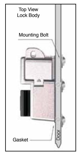
Figure 7 - Mount Lock Body
Deburr all the drilled holes. Remove all debris from the work area after drilling and before proceeding further with any installation. DO NOT use compressed air to remove debris. Flying objects can cause serious injury.
- 10. On the outside of the door, place the lock body gasket over the two bolts to hold it in place.
- 11. Secure (hand tighten only) the G50 lock body using the two bolts.
Note: You will have to back the bolts out from the inside of the door a small amount in order to thread them into the lock body.
- 12. Finish mounting the G50 body from the inside of the door using the remaining 8mm lock body mounting bolts, lock washers, and flat washers (two of each).
- 13. Securely tighten all bolts.
Installation complete.
Operational Check
Make an operational check of the unit by performing the following actions.
- 1. If you have a 6 pin core, insert the black spacer over the driver pins on the figure eight cylinder cutout.
- 2. If you are installing a unit with a core, insert the core using the key marked Control and then use the operating key to ensure that the lock opens correctly. If no core is present, use the black plastic actuator key to operate the lock.
Operational check complete.