gitcon-model-g-152-installation-guide-for-swing-roll-up-doors.pdf_638396
Open the original PDF document
View PDF

Gitcon Model G-152 Installation Guide for Swing & Roll-Up Doors
G-152 Parts
- 1. Lock Body Gasket
- 2. Lock Body mounting bolts and washers
- 3. Lock Body with cable
- 4. Input Unit mounting bolts and washers
- 5. Input Unit
- 6. Handle (6a. Roll-Up or 6b. Swing)
- 7. Handle Mounting Hardware (Not shown in photo)
- 8. Back Plate (8a. Vertical or 8b. Horizontal)
- 9. Cable Routing Plate (9a. Vertical or 9b. Horizontal)
- 10. Test card (not shown).
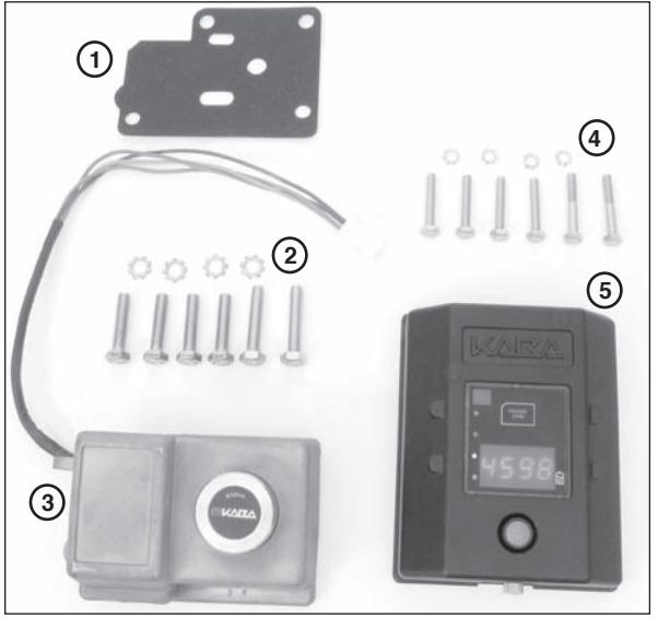
Fig. 1 - Lock Body & Input Unit Parts
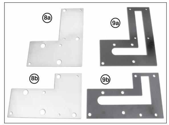
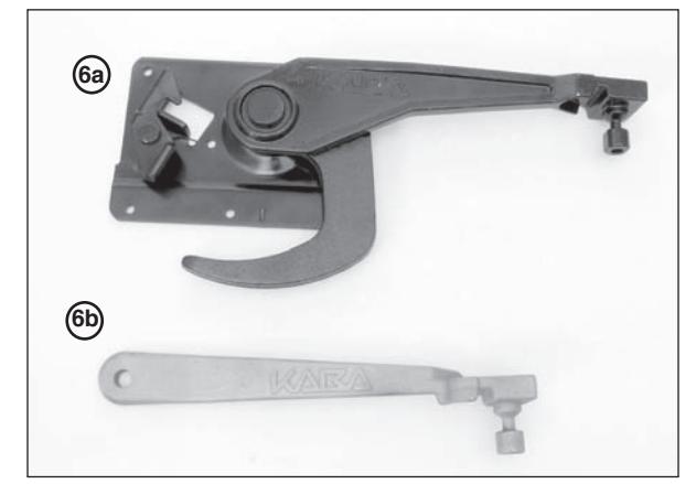
Fig. 2 - Vertical and Horizontal Plates Fig. 3 - Roll-Up Handle & Swing Handle
Symbol Definitions

WARNINGS - Hazards or unsafe practices which could result in personal injury or product or property damage.

NOTES - contain important information and useful tips on the operation of your equipment.
Basic Tools and Materials Required
- • Four new high quality (Energizer®, Duracell®, etc.) AA lithium batteries
- • Pop rivet gun
- • Electric hand drill
- • 8mm (5/16"), 10mm (3/8") and 16mm (5/8") drill bit
- • Appropriate sized drill bit for drilling rivet head on handle (if rivet IS NOT stainless steel)
- • Hand held power grinder (if rivet IS stainless steel)
- • Tape
- • Center punch
- • Adjustable open end wrench or 10mm and 13mm (11mm is also needed on roll-up door installations) sockets/box wrenches
- • Level
- • Hacksaw
- • Hammer
- • Phillips screwdriver
- • Tape measure/Ruler
- • 2mm Allen Wrench (input unit back cover)
Before Drilling
! WARNING
Before drilling any holes ensure that:
- • You are wearing suitable eye protection.
- • Adequate protection is fitted around the surrounding area to protect such things as cables, water/air pipes, etc., from damage.
Before starting any work, determine the position the G-152 is to be located, bearing in mind the following points:
- • Ensure there is no obstruction on the inside of the door.
- • Ensure the vehicle is parked on flat, level ground when installing this lock.
- • Please remember you are installing a high quality, precision lock to a door which, even when new, will have a fair amount of free play in its operation. This free play will only increase with wear as the vehicle is used; therefore, great care must be taken during installation.
Input Unit Preparation
Remove the back of the Input Unit (4 screws) with a 2mm Allen Wrench. Place four new high quality AA lithium batteries in the battery retainers. Reattach the back plate, ensuring that the wires are not pinched. Once the batteries are properly installed, red LED light will flash. Connect the cable to the lock body. Perform the Operational Check (p.7). Disconnect the cable.
Remove Existing Handle

Note: Use a center punch to mark the rivet head before attempting to drill the head off. This will help prevent the likelihood of the drill slipping and damaging the vehicle door. If the rivet is stainless steel, a power grinder may be required to grind off the rivet head.
1. Grind or drill just enough to remove the rivet head and to avoid damaging the door. Once the head has been ground or drilled off, knock the remains of the rivet out using an appropriate sized punch. Remove the handle from the door. (See Figure 4.)

Note: Roll-up doors will have multiple rivets that need to be removed. (See Figure 5.)
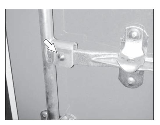
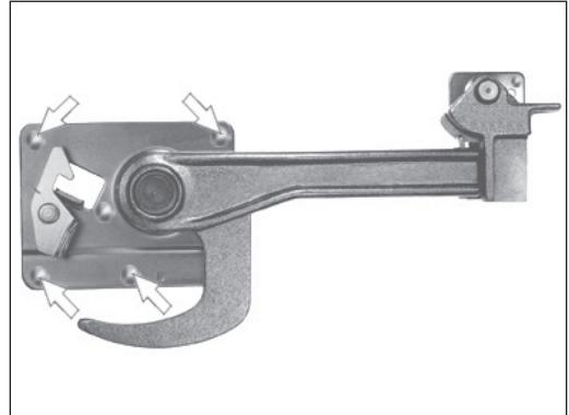
Fig. 4 - Swing Door Fig. 5 - Roll-Up Door
Remove Handle Retainer or Keeper Assembly
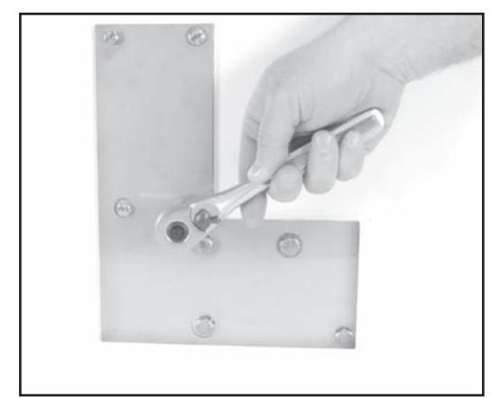
- 1. Drill/grind the bolts out of the handle retainer assembly (for swing door) or the handle keeper (for roll-up door). (See Figure 6 for Swing Door and Figure 7 for Roll-Up Door.)
- 2. Remove the retainer or keeper assembly.
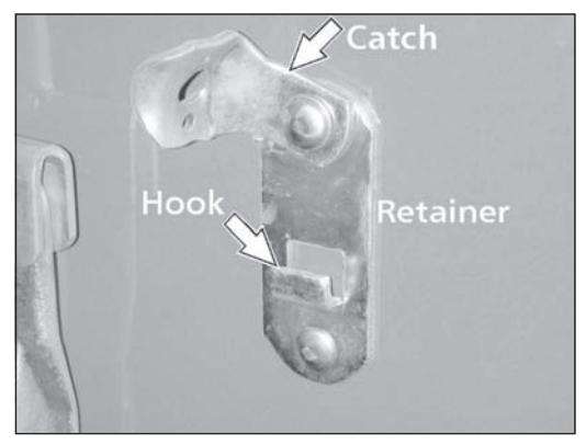
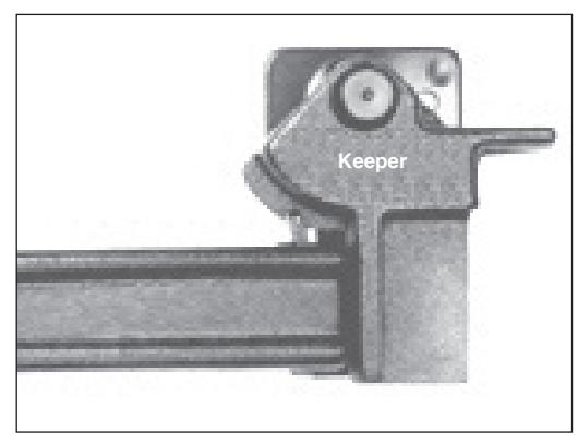
Fig. 6 - Swing Door Fig. 7 - Roll-Up Door
Swing Door
- 1. Attach the G-152 handle to the hub where the old handle was removed, using the pin included in the kit. Insert the pin from the front side of the locking bar.
- 2. Gain access to the rear of the pin. Insert washer and rivet included in the kit. Secure the rivet in position using the pop rivet gun.

Note: If installing on a door with double vertical locking bars, install on the locking bar closest to the hinges.
Roll-Up Door
- 1. With the door closed, align the door handle assembly "J" hook with the center pin/plate of the latch box. Operate handle (open/close) to ensure correct position within the latch box.
- 2. Ensure the handle is level. Use the flat end of the handle. (See figure 8.)
- 3. Using the handle assembly mounting bracket as a template, mark (center punch) the location of the mounting holes.
- 4. Drill the handle assembly mounting holes using an 8mm (5/16") drill bit.
- 5. Insert and seat carriage bolts into supplied handle assembly. Seat carriage bolts by using a hammer to drive the bolts into the mounting plate.
- 6. Mount handle assembly to door and secure from the inside with washer/lock washer/nuts provided.

Note: If necessary, use a hacksaw to remove excess bolt length and grind any resulting sharp edges.
Prep Door for Lock Body
- 1. Using the new handle, close the door(s) fully, ensuring correct shutting for closed position.
- 2. Align template relative to the locking pin on the handle. (See Figure 8.)
- 3. Use tape to secure the template to the door.
- 4. Place the lock body over the coordinating location on the template and rotate the handle to ensure that it clears the lock body. If not, readjust the template.
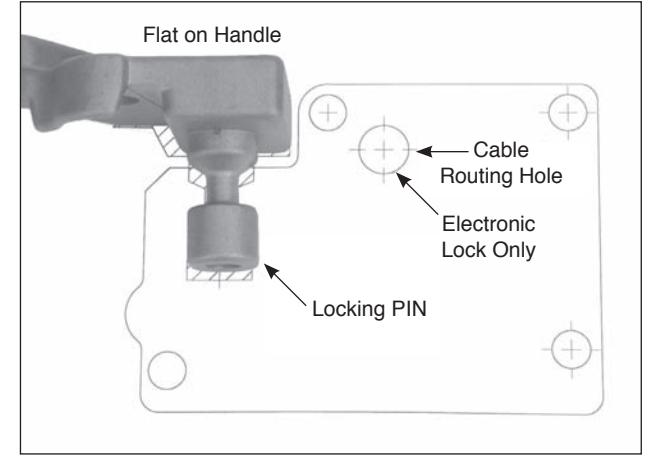
Fig. 8 - Align Template to Handle

Note: If the handle becomes locked in position, connect the cable from the input unit to the lock body and perform the Operational Check (p.7) to unlock and lift the handle.
- 5. Center punch all four mounting holes and cable routing hole.
- 6. Remove the template.
- 8. Drill the four outside lock case mounting holes using a 10mm (3/8") drill bit.
- 9. Drill the cable routing hole using a 16mm (5/8") drill bit.

Note: Ensure that the drill is kept straight when drilling the holes.

Deburr all drilled holes. Remove all debris from the work area after drilling and before proceeding further with any installation. DO NOT use compressed air to remove debris. Flying objects can cause serious injury.
Prep Door for Input Unit
- 1. Temporarily attach the cable routing plate to the front of the door for use as a template, using the lock mounting screws to hold it in place. (See Figure 9.)
- 2. Center punch four mounting holes for the Input Unit.
1 1/4"
Fig. 9 - Use Cable Routing Plate as Template Fig. 10 - Measure & Mark Cable Routing Hole
- 3. Measure and mark an additional 16mm (5/8") hole for cable routing approximately 32mm (1 1/4") from the top of the cable routing plate. (See Figure 10.)
- 4. Remove the cable routing plate.
- 5. Drill the cable routing hole for the input unit using a 14mm 16mm (5/8") drill bit.
- 6. Drill the four mounting holes for the input unit using a 10mm (3/8") drill bit.
Install Lock Body & Input Unit

Note: For Roll-Up Door applications using a Todco (or Whiting General Purpose) handle, use the longer 8mm mounting bolts supplied for the bottom two holes of the lock body and use the longer 6mm mounting bolts supplied for the bottom two holes of the input unit.
- 1. Start to attach the two cable routing plates to the inside of the door using two of the lock body mounting bolts and two lock washers. Attach through the upper right and lower left corners of the lock body mounting holes.
- 2. On the outside of the door, place the lock body gasket over the two bolts to hold it in place.
- 3. While holding the lock body, route the cable through the gasket and the cable routing hole for the lock body.
4. Secure (hand tighten only) the G-152 lock body using the two bolts. (See Figure 11.)

Note: You will have to back the bolts out from the inside of the door a small amount in order to thread them into the lock body.
- 5. Route the cable through the cable routing hole for the input unit.
- 6. Insert two of the input unit mounting bolts and washers through the back of the door. Use the upper right and lower left corners of the input unit mounting holes.
- 7. Connect the lock body and input unit cable.
- 8. Place excess cable back in the input cavity via the cable routing hole.
- 9. Secure (hand tighten only) the input unit using the two bolts. (See Figure 13.)

Note: You will have to back the bolts out from the inside of the door a small amount in order to thread them into the input unit.
10. Tape the cable in place in the routing channel so that it does not get pinched when the back plate is attached.
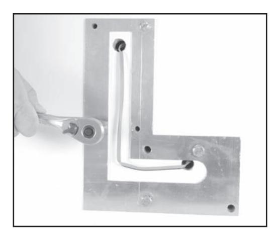
Fig. 13 - Secure Input Unit from Back of Door Fig. 14 - Attach Back Plate
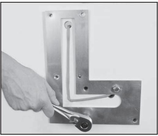
Fig. 11 - Secure Lock Body from Back of Door
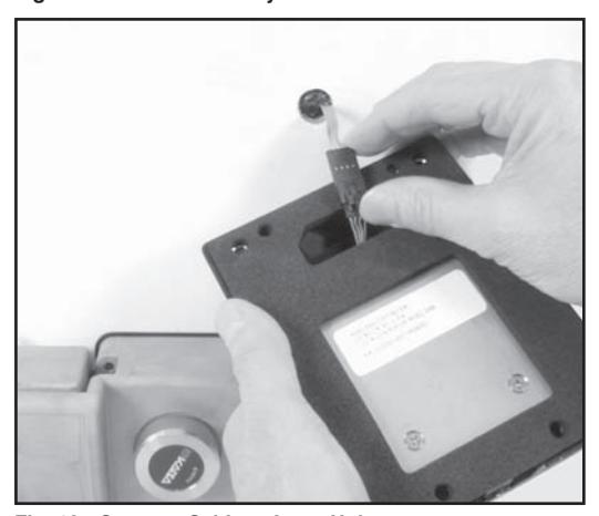
Fig. 12 - Connect Cable to Input Unit
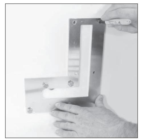
- 11. Attach the back plate over the cable routing plate with the four remaining bolts, ensuring the cable does not get pinched. The cable must stay in the channel of the cable routing plate. (See Figure 14.)
- 12. Securely tighten all bolts.
- 13. Before closing door, place handle in lock body and perform operational check.
Note: If handle will not go into the lock body, loosen the lock body bolts, reposition lock body to accept handle and re-tighten bolts.
14. Close the door(s) and place the handle in the lock body.
Perform the operational check prior to installing the Lock assembly. If the G-152 has been previously
installed, perform the operational check prior to closing the door.
Make an operational check of the unit by performing the following actions. (See Figure 15 for reference.)
- 1. Connect the Lock Body and input unit cable.
- 2. Activate the input unit by pressing and releasing the RED switch button.
- 3. "Open" will appear on the LED display.
- 4. Insert (latch) the operating handle locking pin into the lock body.
- 5. Press and release RED switch button.
- 6. Press and release RED button again with "UNLK" prompt.
- 7. GREEN light flashes.
- 8. Present Test Card to input unit transponder "RFID" communication area.
- 9. Turn dial on lock body to the left to release the handle.
- 10. Lift operating handle.
Operational check complete.
Battery Maintenance - Temporary Power
Replace Batteries
The four AA batteries located within the Input Unit should be replaced when the "Battery Low Indicator" illuminates. To replace batteries, complete the following steps:
- 1. Remove the input unit from the door (4 mounting bolts) and disconnect cable.
- 2. Remove the back plate of the input unit (4 screws) and the four AA batteries in the battery retainer. Replace the batteries with four new high qualityAAlithium batteries. Once the batteries are properly installed, the low battery indicator light will flash.
- 3. Reattach the back plate of the input unit.
- 4. Reconnect the cable and reinstall input unit.
- 5. Before closing the door, perform an operational check of the lock with the appropriate opening procedure as defined for the input unit.
Temporary Power
An external 9V supplementary power connector is provided to supply temporary power to the input unit. The 9V connector is located at the base of the input unit and is accessible by turning the knurled knob. It is recommended that you use a new high quality battery.
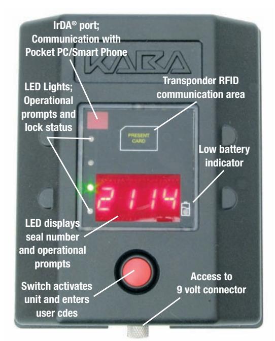
Fig. 15 - Input Unit Operation
Maintenance and Trouble-Shooting
Maintenance
- • Inspect the door assembly to assure proper alignment and operation.
- • Inspect the G-152 mounted door panel for defects and repair/replace as recommended by the manufacture.
- • Verify lock body and input unit mounting hardware is secure.
- • Open and close lock assembly to assure all components are properly aligned and in good operating condition.
- • Inspect physical condition of handle-mounted "Weather Guard" and replace if needed.
- • Keep Lock Body locking jaws clean and remove any debris.
- • Apply a Dry Film Lubricant to the Lock Body locking jaws.
- • Replace Input Unit batteries at least once a year. See page 7 Battery Maintenance.
Winter Conditions
- • If lock becomes frozen, apply de-icer as required to the:
- Lock Body locking jaws
- Lock Body operating dial
- • Input Unit RED button switch
- • Apply a 9-volt battery to the supplementary power connector if cold weather conditions impair the Input Unit/Lock Body operation. See page 7 Temporary Power.
Trouble-shooting
• If the Input Unit/Lock Body operation malfunctions, apply a 9-volt battery to the supplementary power connector. If operations resume, replace the Input Unit batteries. See page 7 "Battery Maintenance-Temporary Power".
Notice: Information in this document is subject to change without notice. Kaba Mas shall not be liable for technical or editorial errors or omissions contained herein; nor for incidental or consequential damages resulting from the furnishing, performance or use of this material.
© 2006 Kaba Mas LLC. All rights reserved.
Kaba Mas LLC 749 W. Short Street, Lexington, KY 40508 USA Phone: (859) 253-4744 FAX: (859) 255-2655 Technical Support: (800) 950-4744 www.kaba-mas.com