e-Smart Installation
Open the original PDF document
View PDF


| Table of Contents | ||
|---|---|---|
| Package Content | 2 | |
| Getting Started & Handing information | 3 | |
| Door Preparation | 4 | |
| Step 1 - Adjusting Deadbolt | 5 | |
| Step 2 - Installing Deadbolt & Strike | 6 | |
| Step 3 - Setting Tail Piece | 7 | |
|
Step 4 - Installing Outside
Outside Assembly |
8 | |
| Step 5 - Installing Backplate | 9 | |
| Step 6 - Routing Cable | 10 | |
| Step 7 - Installing Inside Assembly | 11 | |
| Step 8 - Installing Inside Cover | 12 | |
| Exploded View | 13 | |
Troubleshoot 14

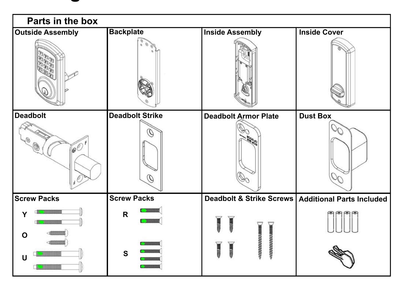
Getting Started

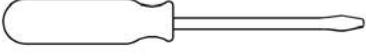
Tools needed for lock installation
Phillips Screwdriver (Not included)

Flat-Head Screwdriver (Not included)
Note:
Do not use a power drill for installation of lock - it can damage the lock.
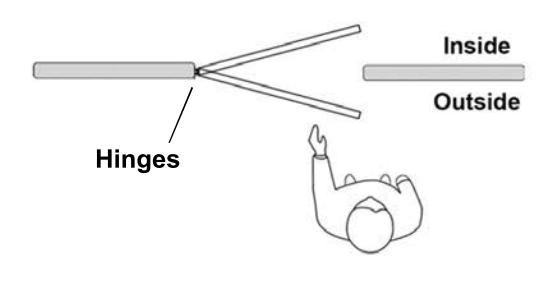
Handing Information
If hinges are on the right, and the door opens inward or outward it is a right hand door (RH)
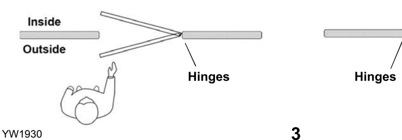
If hinges are on the left, and the door opens inward or outward it is a left hand door (LH)
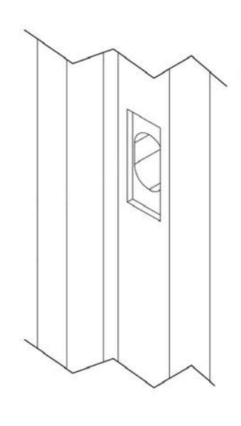
Door Preparation

Prepare door and jamb per template provided. The backset is the dimension from the edge of the door to the centerline of the lock.
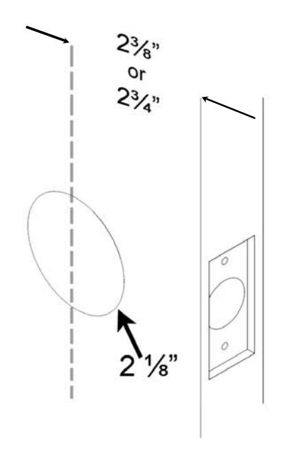
Important:
Door stop is where the door will stop when normally operated. The stop includes any gasket, smoke seal, or bumpers. bumpers. The position of strikes are to be measured taking this into account.
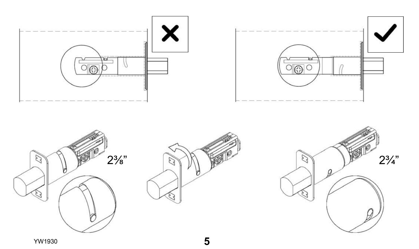
Step 1

Place the deadbolt in the door frame cutout and make sure the cross shaped hub is centered. Otherwise, look below on how to adjust the deadbolt by rotating the deadbolt face.
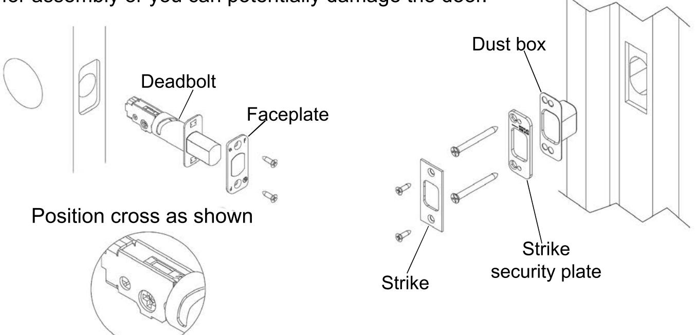
Step 2

Install the deadbolt and faceplate and secure with 2 screws. Install strike, strike security plate, and dust box. Secure with 4 screws.
Note: During installation keep the door open. Do not use power tools for assembly or you can potentially damage the door. Dust box

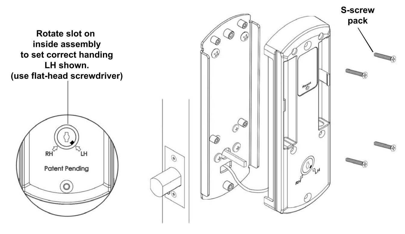
Set the handing on the outside assembly.
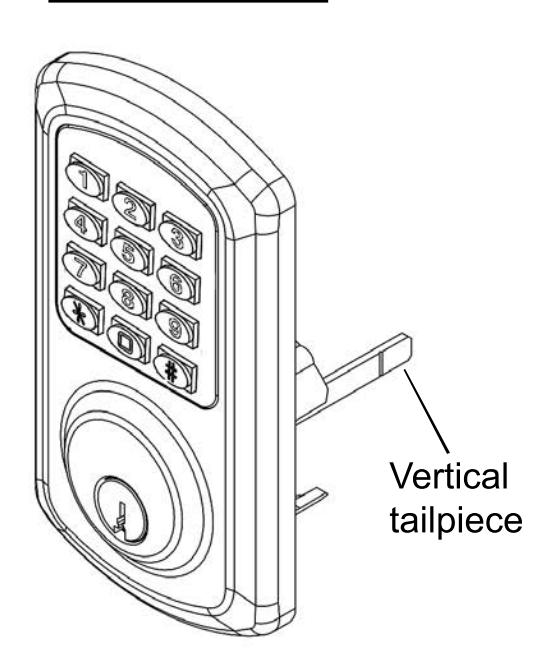
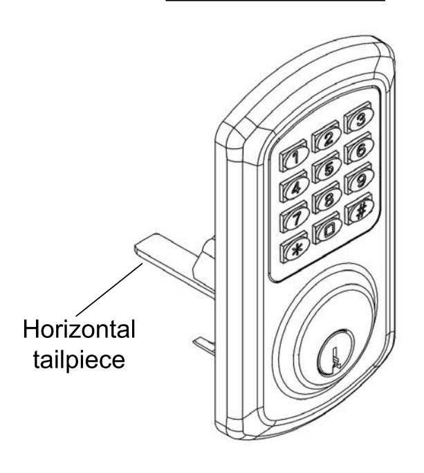
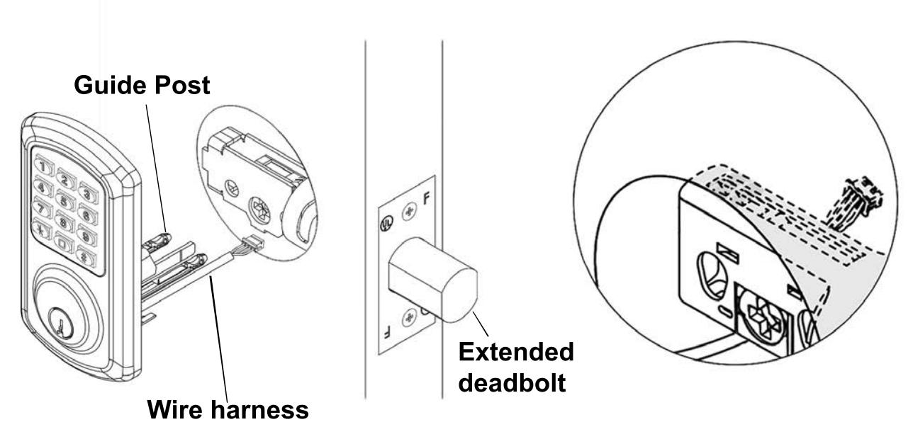
Step 4

Install the outside assembly. Route the wire under the deadbolt and the tail piece through the cross. The two plastic guide posts should go through the holes on both sides of the cross.
Note: A left hand (LH) lock will be depicted in the following guide. For right hand install opposite. Make sure the deadbolt is extended.
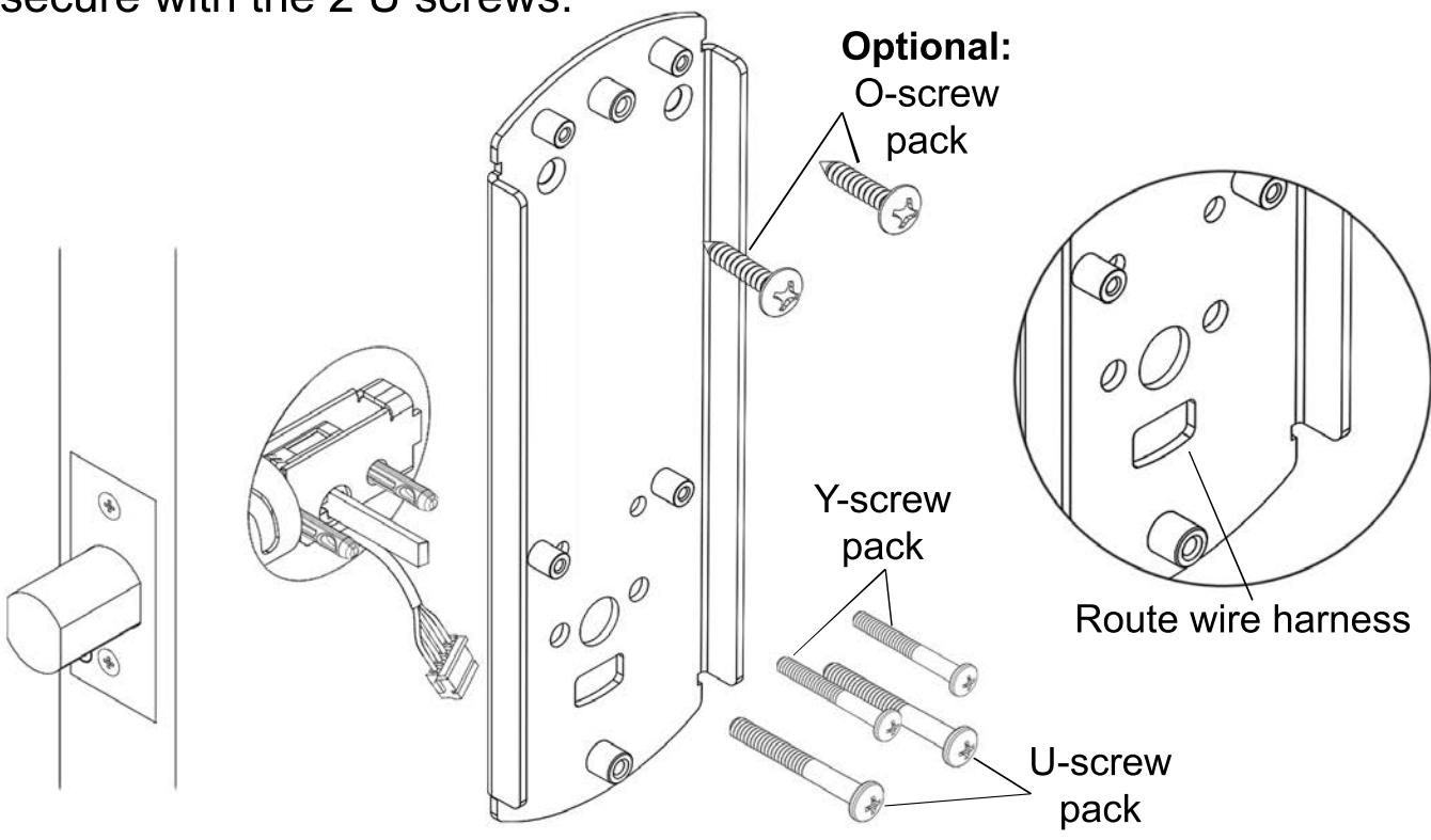
Install the backplate using the Y and U screw packs. Route the wire harness through the lower cutout. Secure with the 2 Y screws on the top two holes. Remove the two guide posts and secure with the 2 U screws.

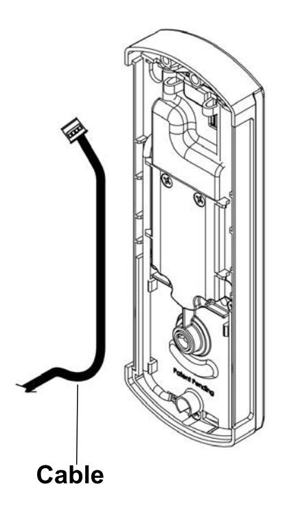
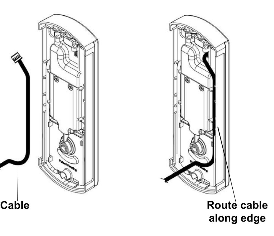
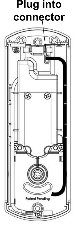
Guide cable through door cutout. Plug cable connector into inside assembly connector, route cable along edge and tuck cable into the side channel as shown.

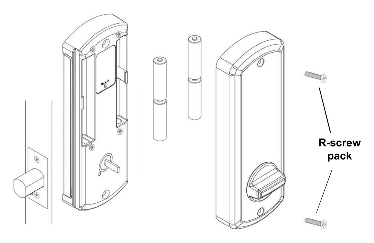
Set the handing on the inside assembly. Install the inside assembly using the S-screw pack.

IMPORTANT- After adding batteries, see programming manual on SETTING THE HANDING before operating the keypad. Once the handing has been set, install inside cover using the R-screw pack.
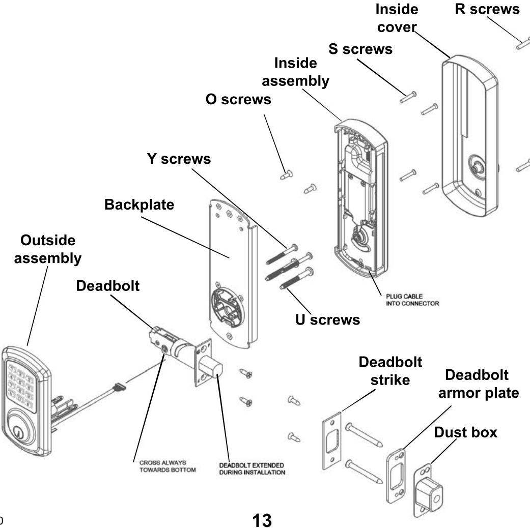
Exploded view


| Problem | Cause | Solution |
|---|---|---|
| Keypad does not light up. | Batteries are dead. |
Replace batteries by removing
back cover. |
|
Keypad is locked out due to
amount of incorrect codes |
Wait 60 seconds and try again. | |
|
Not fully plugged in wires or
pinched wires. |
Check wire connection. | |
| Deadbolt does not fully extend. | Strikes are not aligned. |
Adjust strikes. (See door
template) |
|
Deadbolt is jammed and does
not extend or retract. |
Handing was not set correctly
on outside assembly. |
Set handing correctly on
outside assembly. (See Step 3) |
|
Deadbolt was not extended
during installation. |
Take lock off door and re-install
with deadbolt extended. (See Step 4) |
|
|
Keypad lights up but deadbolt
does not respond. |
Handing has not been set on
the keypad |
With deadbolt extended, press
1-2-3-4-5. See Step 7. |

VISIT WWW.TOWNSTEEL.COM FOR
17901 RAILROAD STREET CITY OF INDUSTRY, CA 91748 TOLL FREE: 877-858-0888