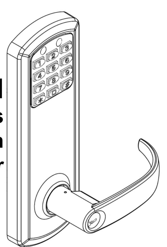
e-Genius Installation
Open the original PDF document
View PDFTownSteel e-Genius 2000 Series Lock Installation 5 1/2" Center To Center
| Table Of Contents | |
|---|---|
|
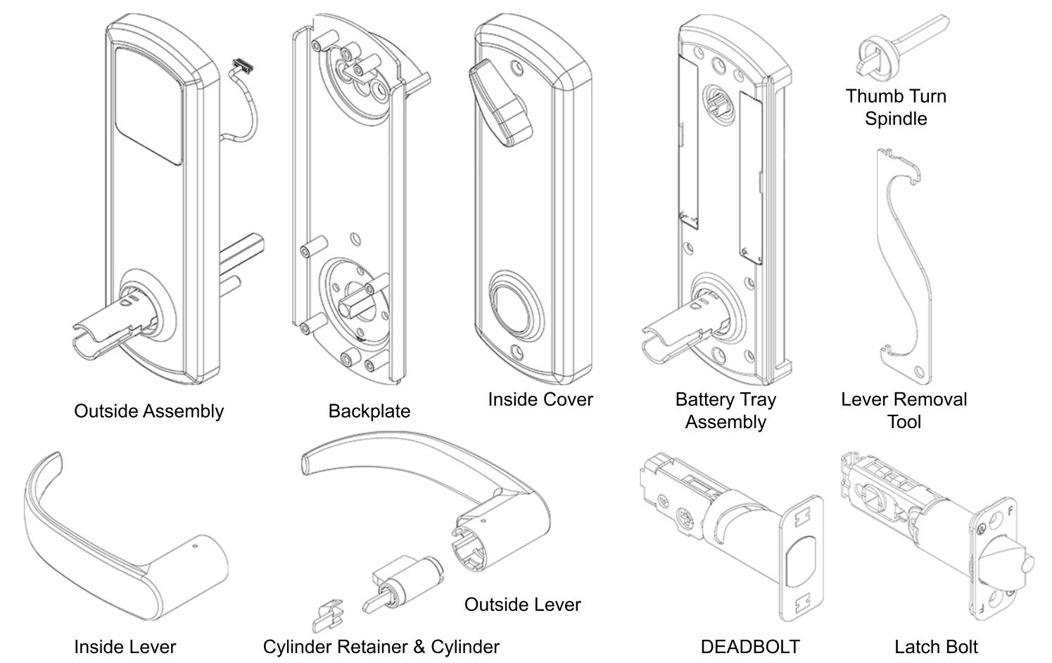
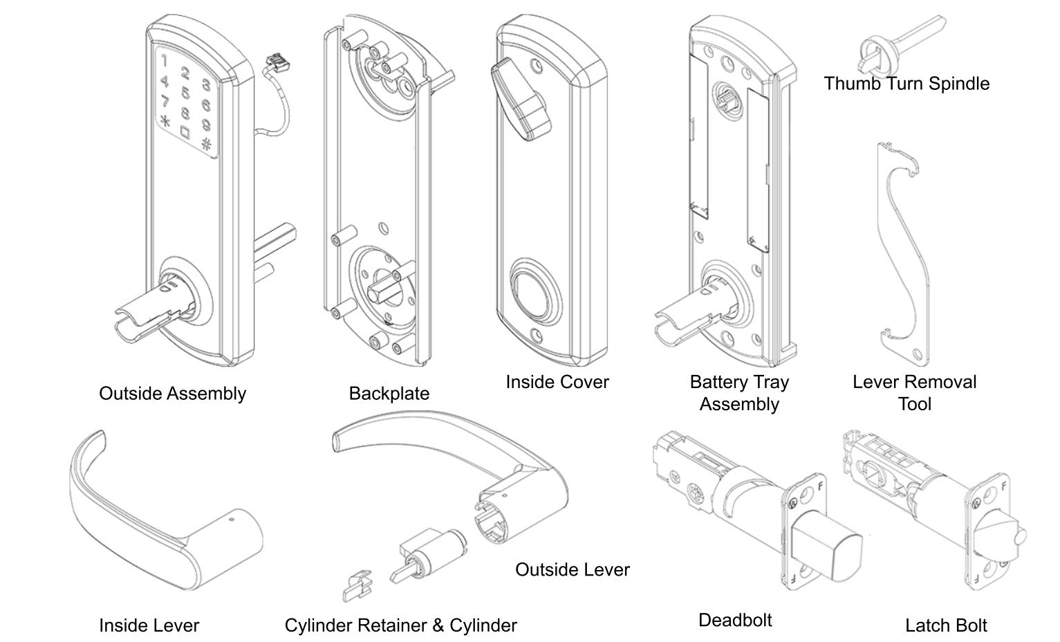
Package Content
Getting Started |
2
4 |
| Handing Information | 5 |
| Door Preparation | 6 |
| Step 1 - Adjust Latch Bolt | 7 |
| Step 2 - Set Handing On Latch Bolt | 8 |
|
Step 3 -
- Adjust Deadbolt |
9 |
| Step 4 - Install Deadbolt And Latch Bolt | 10 |
| Step 5 - Install Outside Lever | 11 |
| Step 6 - Install Outside Assembly | 12 |
| Step 7 - Install Backplate | 13 |
| Step 8 - Install Spindle And Connect Battery Tray | 14 |
| Step 9 - Set Handing On Battery Tray | 15 |
| Step 10 - Install Batteries | 16 |
Addendum A - Change Handing Information Addendum C - Change Handing On Outside Assembly
1
Step 11 - Install Escutcheon And Inside Lever
Step 12 - Install Strikes
Exploded View Of Lock
Troubleshoot
YW1930
Addendum B - Remove Levers
YW1930

2
Package Content

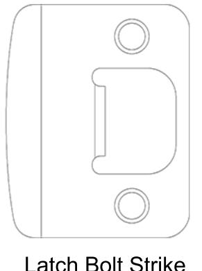
Latch Bolt Strike Deadbolt
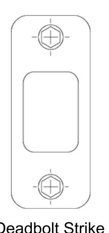
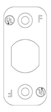
Deadbolt Strike
Armor Strike
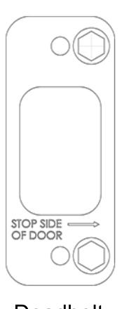
Deadbolt Faceplate
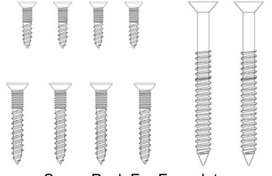
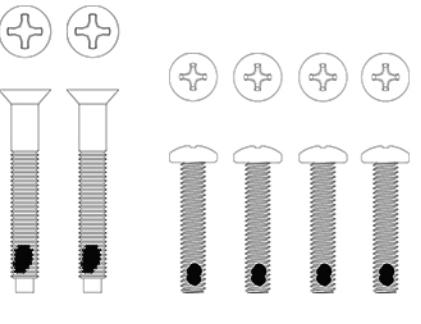
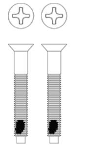
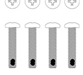
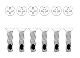
Screw Pack For Lock Assembly Screw Pack For Faceplate and Strike Installation
3
Getting Started

This is an interconnect lock. Inside is always unlocked. Deadbolt can be extended from inside or outside by lifting lever or using thumbturn on the inside. From inside, rotating lever down will retract both bolts. From the outside, presenting a valid user code and rotating the lever down will retract both bolts.
Key Override
Rotating the key clockwise, approximately 90 o -120 o , will allow you to rotate the lever and retract both bolts. The key will not retract the bolts. Return key back to home position to pull out key.
Tools Needed For Lock Installation
Phillips screw driver Flat Head screw driver
Note:
Do not use a power drill for installation of lock as it can damage lock.
Tools May Be Needed For Door Preparation
Tape Measure Power Drill (For drilling holes ONLY)
1" and 2 1/8" Drill Bits
Wood Chisel
Pencil
7/64 Hex Wrench
When batteries are installed and lock is ready to be operated, refer to programming guide for programming instructions.
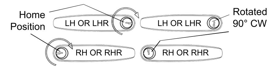
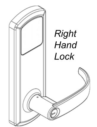
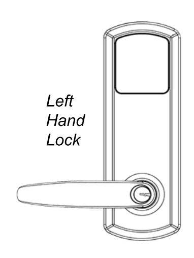
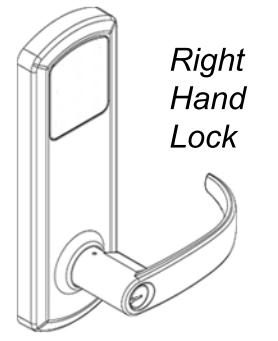
Handing Information

Interconnect lock is handed. See handing information below.
Handing Information From Outside
If hinges are on the left, and door opens inward, it is a Left Hand Door(LH).
If hinges are on the left, and door opens outward, it is a Left Hand Reverse Door(LHR).

If hinges are on the right, and door opens inward, it is a Right Hand Door(RH).
If hinges are on the right, and door opens outward, it is a Right Hand Reverse Door(RHR).
If handing needs to be changed, see Addendum A (Page 19).
5
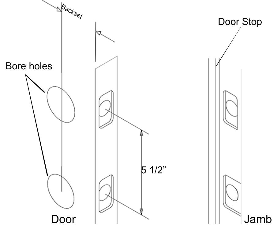
Door Preparation

Prepare door and jamb per template provided. Backset is adjustable for 2 ³⁄" or 2 ³⁄". The backset is the dimension from the edge of the door to centerline of the lock. This lock requires a 5 ¹⁄" center to center distance between the bore holes.
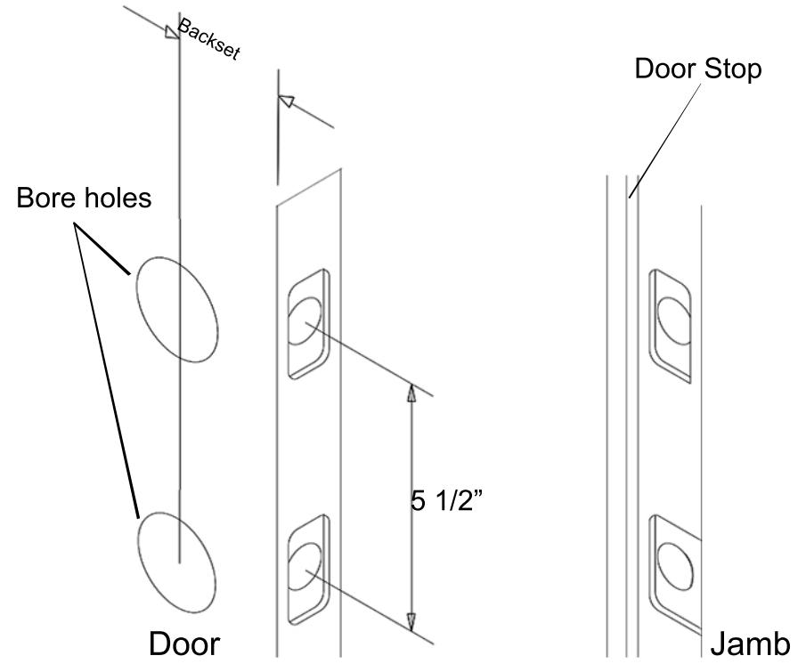
IMPORTANT:
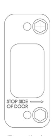
Door stop is where the door will stop when normally operated. Door stop includes any gasket, smoke seal, or bumpers. Position of strikes are to be measured from where the door actually stops. The deadbolt, when thrown, cannot have any interference with the deadbolt strike. If there is any interference, strikes need to be adjusted for lock to work properly.
YW1930
6
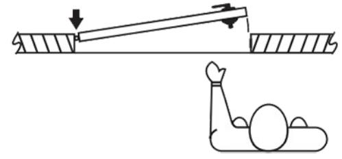
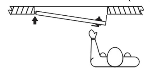
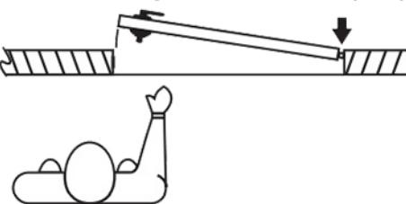
Adjust latch bolt by adjusting hub.
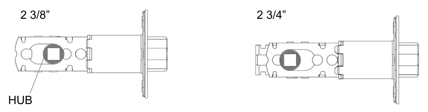
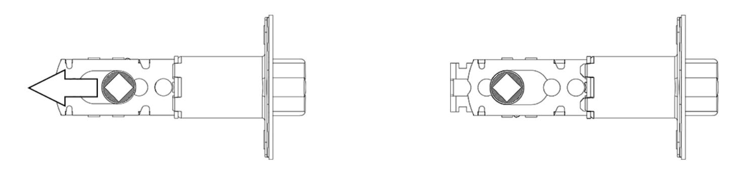
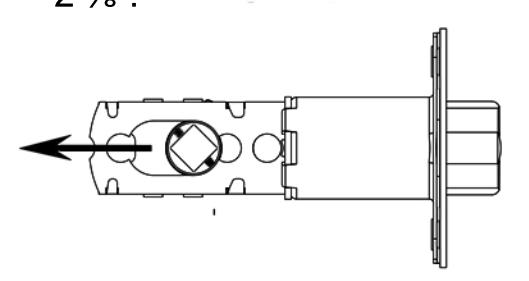
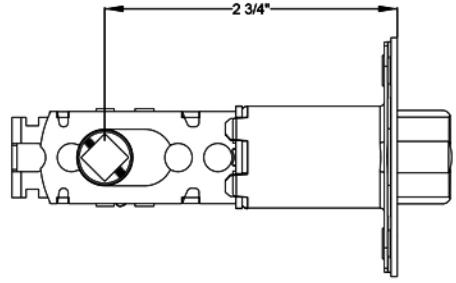
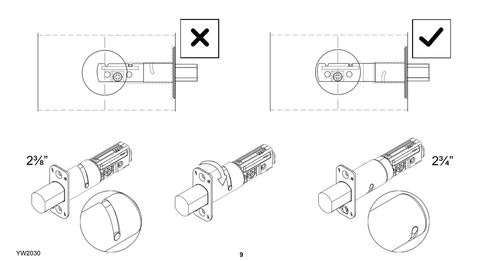
To adjust from 2 3/8" to 2 3/4", rotate hub on the diagonal as shown below. Pull hub to the left. Push hub to the right to go back to 2 3/8".
7
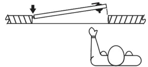
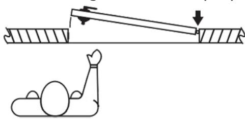
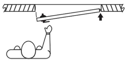
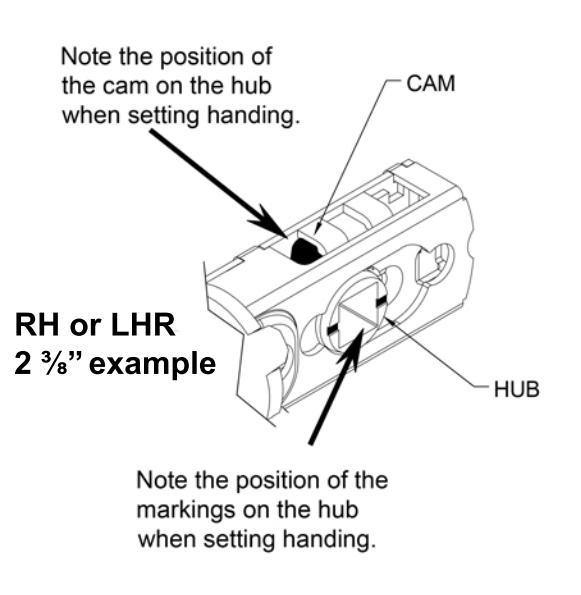
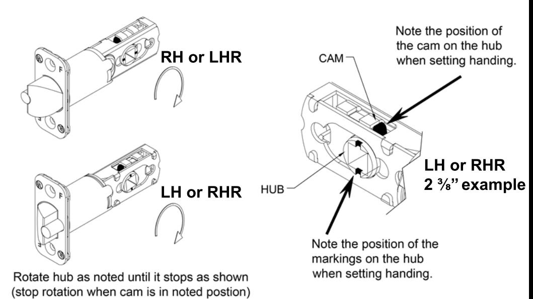
After setting backset, the latch bolt needs to be handed for LH, RH, LHR, and RHR doors. Rotate hub as specified. 2 ³⁄" latch depicted below. For 2 ³⁄", latch should remain extended after rotation.
8
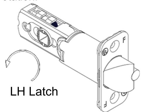
Note: Rotate hub counter clockwise until latch matches image shown
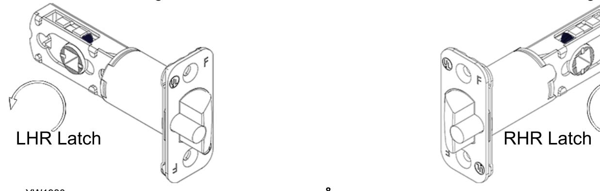
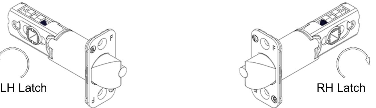
Note: Rotate hub clockwise until latch matches image shown
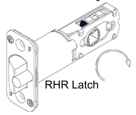
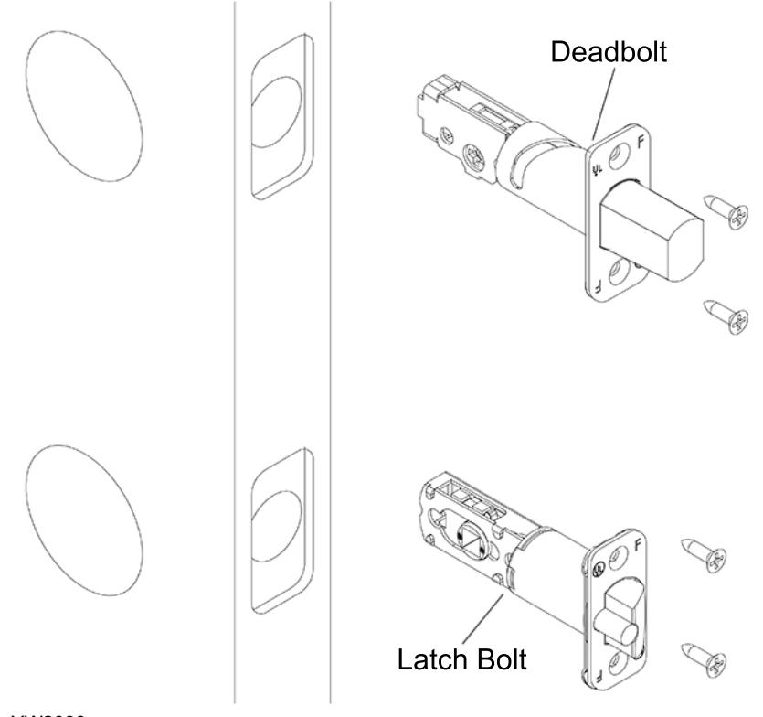
Place the deadbolt in the door frame cutout and make sure the cross shaped hub is centered. Otherwise, look below on how to adjust the deadbolt by rotating the deadbolt face.
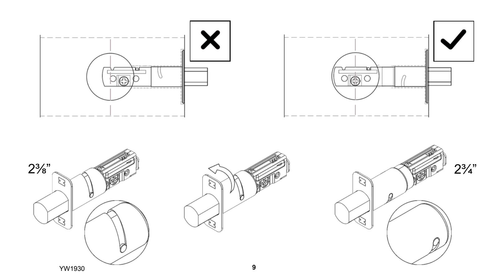
Extend deadbolt. Install deadbolt, deadbolt faceplate, and latch bolt as shown (RH Shown). Secure with 4 screws.
10
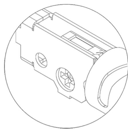
Position cross as shown below.
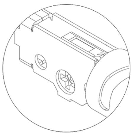
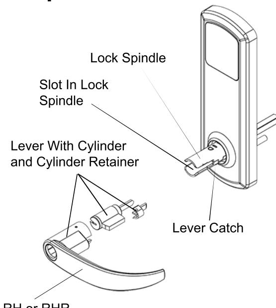
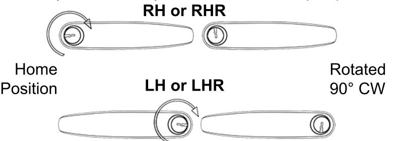
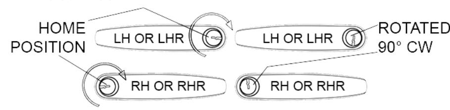
Lever Orientation
Lever Catch Slot In Lock Spindle Lever With Cylinder and Cylinder Retainer RH or RHR Lock Spindle
Install Outside Lever
1) Insert key and rotate cylinder 90° clockwise(CW).
*Note: LH lever and RH lever orientation
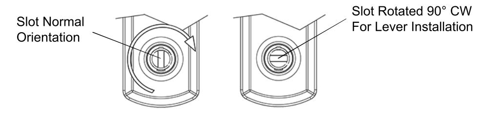
2) Use a flat head screw driver to rotate slot in spindle 90° CW on outside assembly.
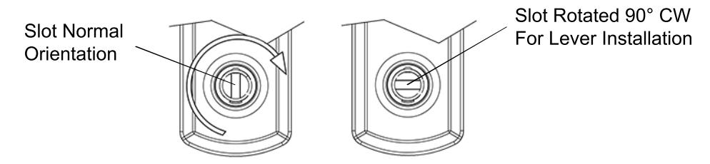
3) With key inserted and rotated 90° CW, push lever onto outside assembly while the slot is also rotated 90° CW. Lever catch is on underside of lever and it should snap into place. Rotate keyway back to home position and pull out key. Pull lever to make sure lever is secure.

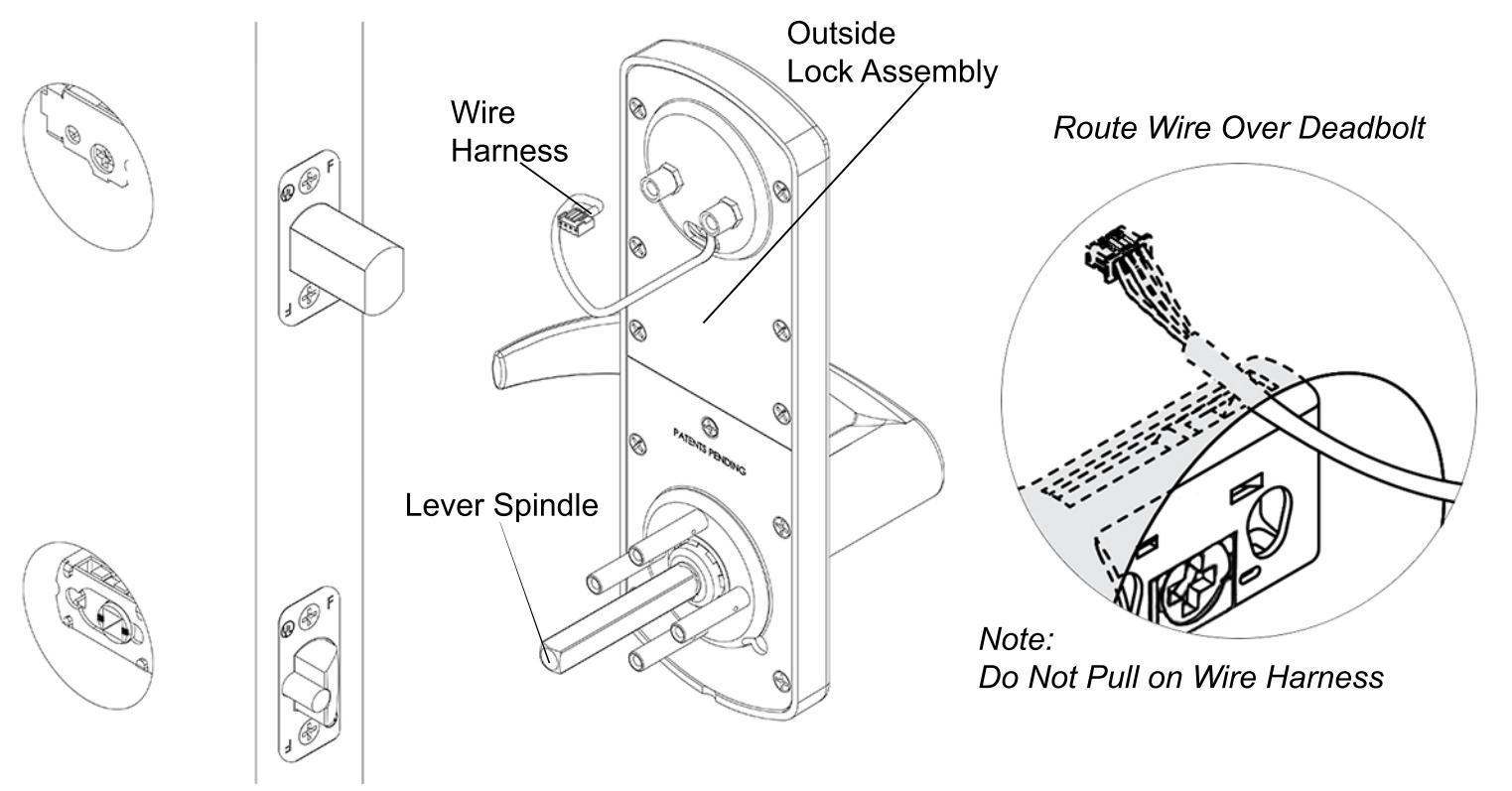
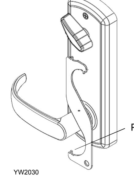
Align outside lock assembly and install onto door face. Lever spindle goes through latch hub. Carefully guide wire harness through and over deadbolt housing.
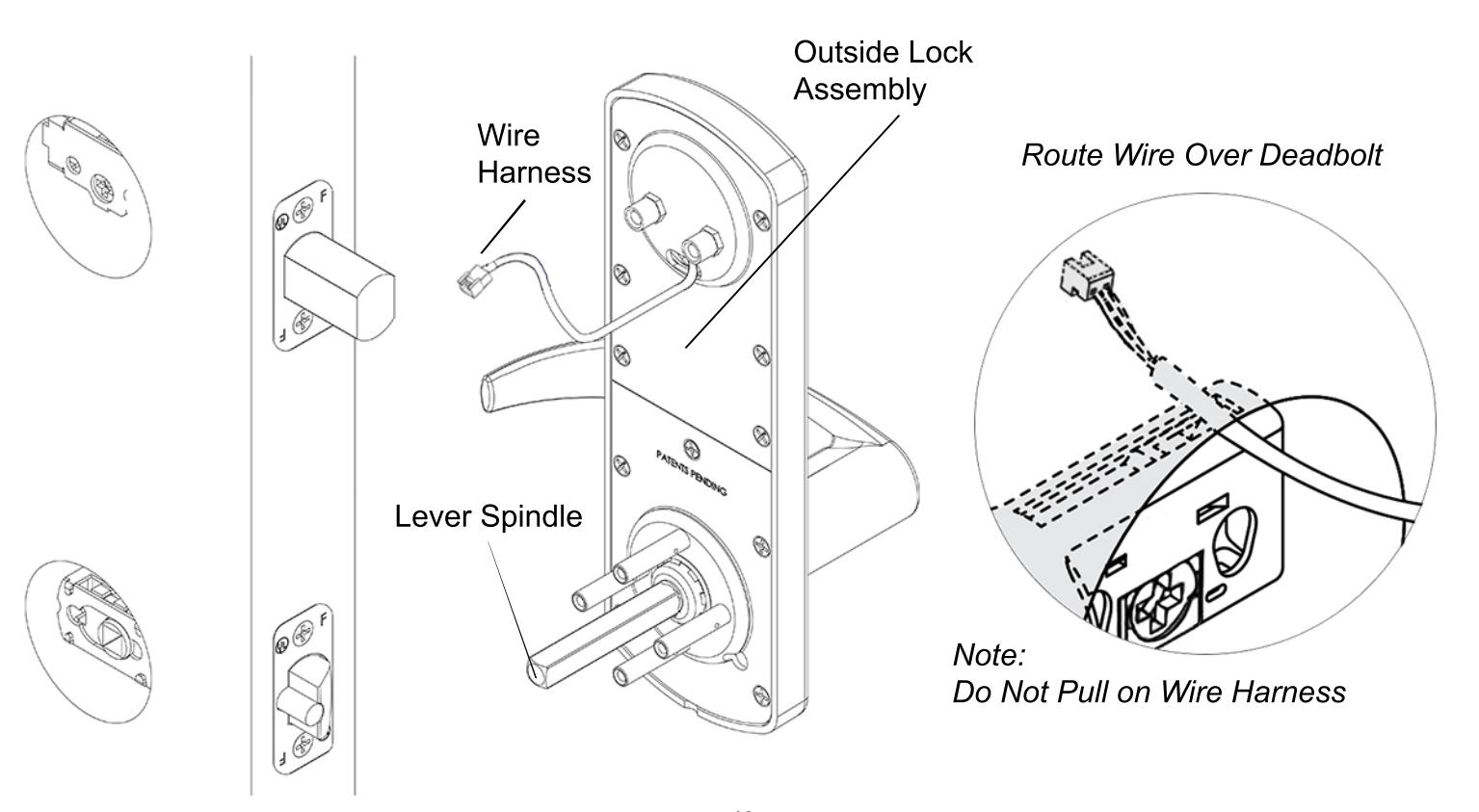
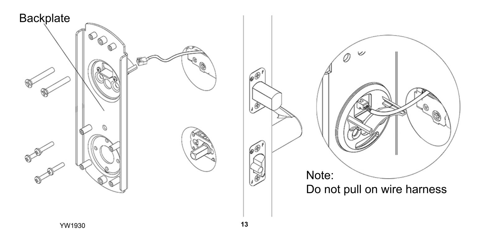
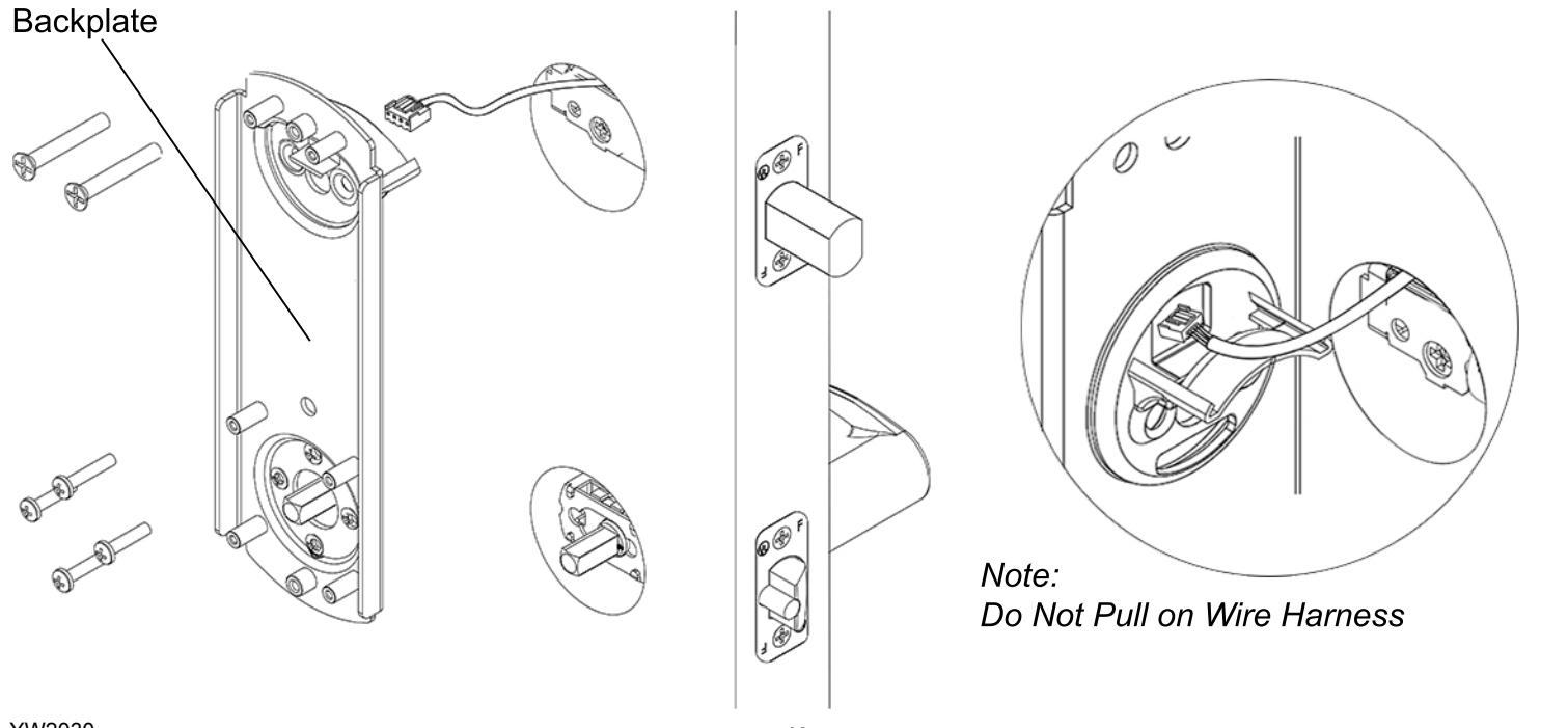
Align backplate and install on the door. Guide the wire harness above the shelf on backplate and down through the slot. Secure top of backplate with 2 screws that go through the deadbolt housing - do not tighten until all screws on the backplate are installed. Secure bottom of backplate with 4 screws. Tighten all screws on backplate.

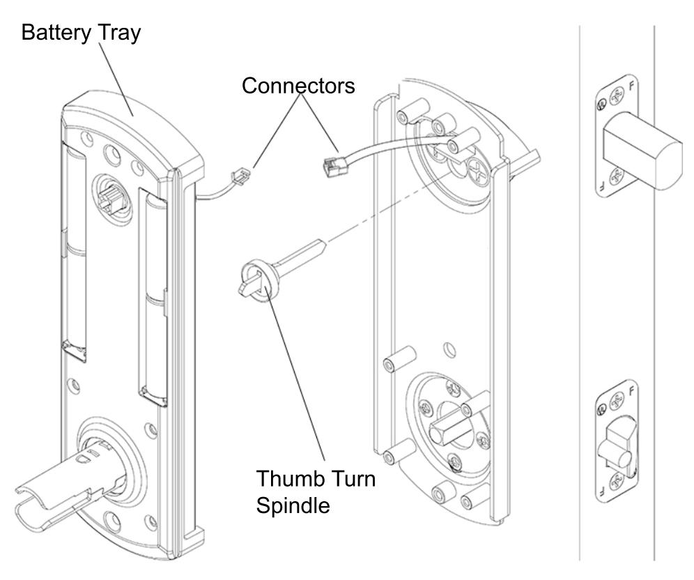
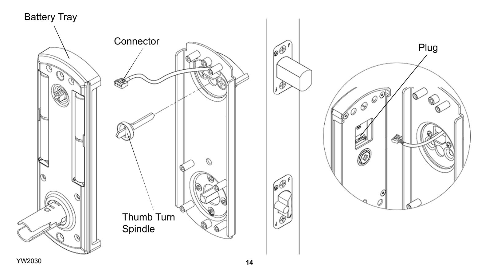
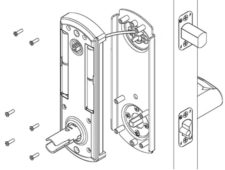
Install thumb turn spindle as shown. Plug in connector from lock assembly into connector from battery tray.

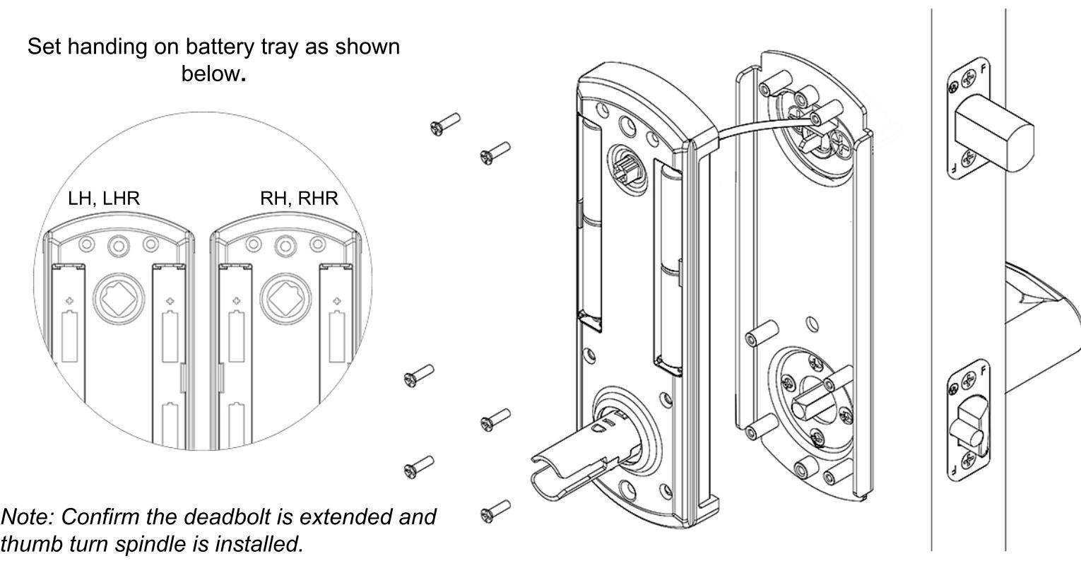
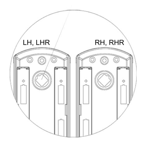
Set handing on battery tray. Push excess wire into hole over the backplate. Battery tray should sit flush without interference. Do not pinch wire harness. Secure battery tray with 6 screws.
YW1930
15

Install 4 AA-alkaline batteries into battery tray. Use only alkaline batteries for the interconnect lock.

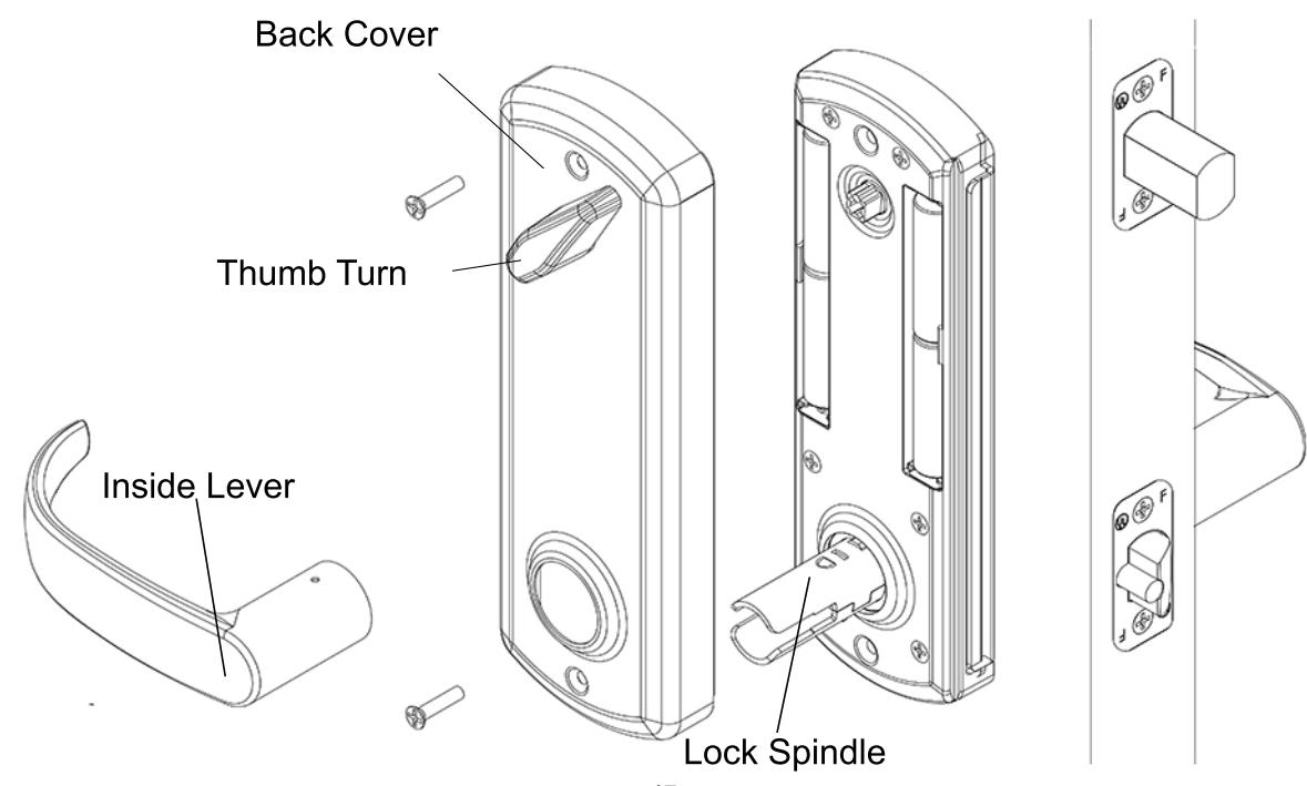
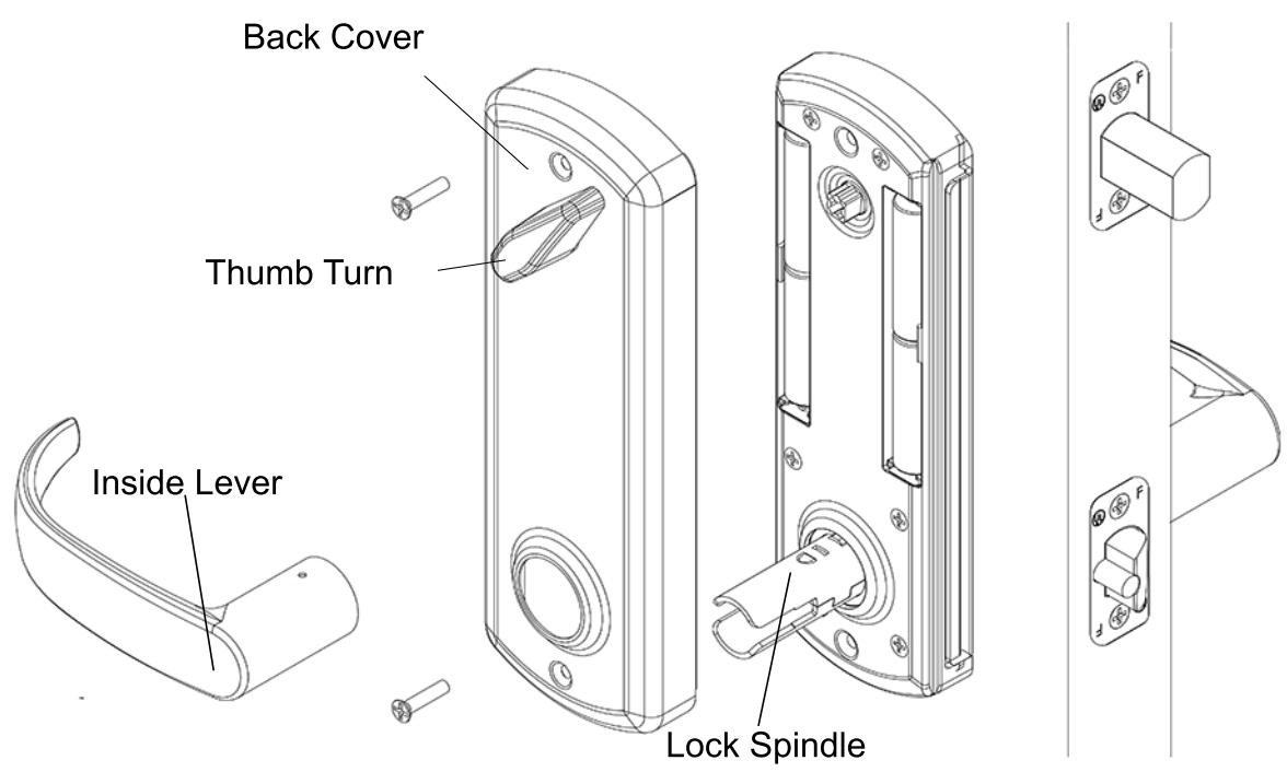
Place back cover over battery tray. Make sure the thumb turn on the back cover is oriented properly. Align thumb turn until it falls into place without forcing it. Secure back cover with 2 screws. Slide inside lever onto lock spindle. Lever catch is on underside of lever and it should snap into place. Pull lever to make sure it is secure.

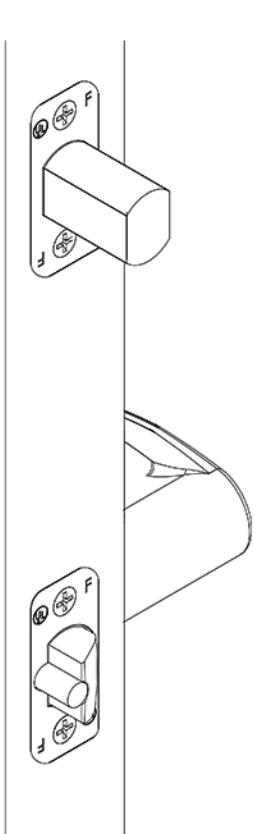
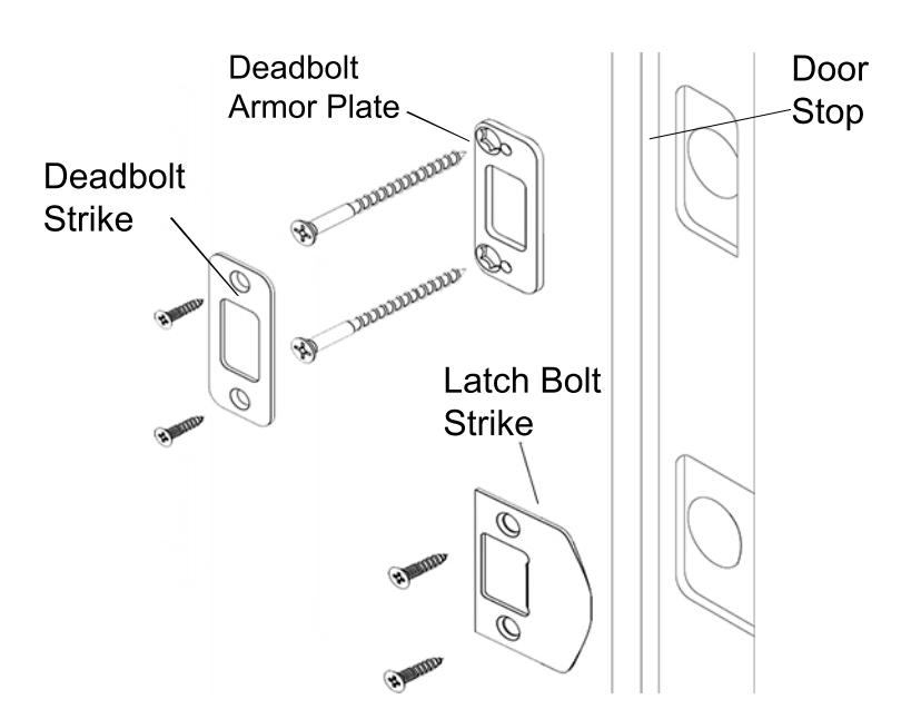
Install deadbolt armor plate, deadbolt strike, and latch bolt strike. Secure with 6 screws.
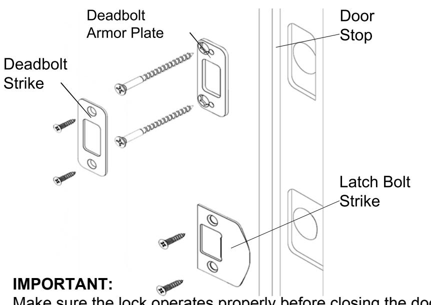
Remember, the door stop is where the door will stop when normally operated. Stop includes any gasket, smoke seal, or bumpers. Position of strikes are to be measured from where the door actually stops. The deadbolt, when thrown, cannot have any interference with deadbolt strike. If there is any interference, strikes need to be adjusted for the lock to work properly.
Make sure the lock operates properly before closing the door. From inside, lifting the lever should extend the deadbolt and rotating the lever down should retract both bolts. From outside, lifting the lever should extend the deadbolt. Press the following keys on the keypad to check proper function, enter 1-2-3-4-5. The LED will light red then green. Rotating the lever down should retract both bolts. Key override, rotating the key unlocks the lock momentarily allowing the lever to retract both bolts. When key is removed, the lock will return to being locked.
YW1930 18
Addendum A

Changing the handing should not be needed. Lock is shipped with handing specified. See shipping confirmation or box for details.
If handing needs to be changed from Right Hand to Left Hand (Or Left Hand to Right Hand), handing must be changed on outside assembly. This entails changing a socket head screw on the back of outside assembly. Also, latch bolt and levers need to be adjusted.
See:
Addendum C To change handing on outside assembly Addendum B To remove and adjust levers Step 2 To adjust latch bolt
If handing needs to be changed from Right Hand to Right Hand Reverse (Or Left Hand to Left Hand Reverse), only the latch bolt orientation needs to be changed.
See:
Step 2 In order to adjust latch bolt
Addendum B
Remove Inside Lever
YW1930
- 1) Insert prong on lever removal tool in the hole on underside of the lever.
- 2) Lift up the lever removal tool to depress the lever catch and pull the lever off.
Remove Outside Lever
1) Insert the mechanical key and rotate it 90° clockwise.

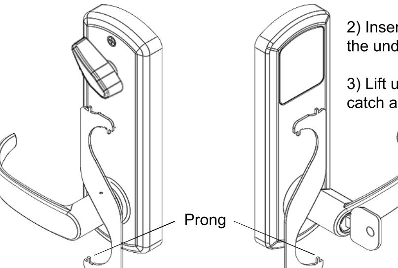
- 2) Insert prong on lever removal tool in the hole on the underside of the lever.
- 3) Lift up the lever removal tool to depress the lever catch and pull the lever off.
Change Handing On Outside Assembly
For this example, we will be changing the handing of a right hand lock to a left hand lock .
1) Remove lock assembly from door.
3) To change handing, rotate lever up and install socket head screw on the left side of lock assembly.
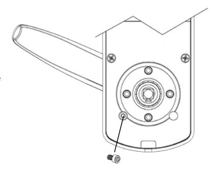
4) Re-install lock assembly on door.
*Be sure to change lever to new handing. See Install Outside Lever for more information.
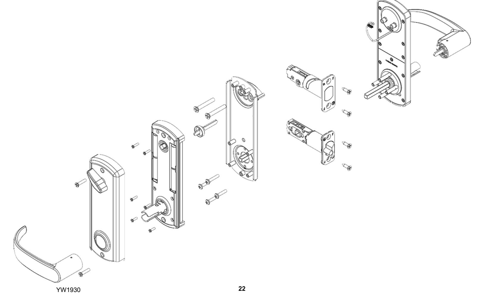
Exploded View Of Lock


| PROBLEM | CAUSE | SOLUTION |
|---|---|---|
| Keypad does not light up. | Batteries are dead. | Replace batteries by removing back cover. |
|
Keypad is locked out due to x amount of incorrect
codes. |
Wait 60 seconds and try again. | |
| Not fully plugged in wires or pinched wires. | Check wire connection. | |
|
Latch bolt retracts when lever is rotated
up, not down. |
Hub on latch bolt was not installed
correctly. |
Take lock off door and re-adjust latch bolt.
(See Step 2) |
|
Rotating outside lever up will not extend
deadbolt. |
Deadbolt was not extended during
installation. |
Remove inside lever, back cover, and
battery tray extend deadbolt and re-install parts. (See Step 8) |
|
Key will not come out of lever after
installation. |
Key cylinder was not installed correctly. |
Use lever removal tool to remove lever and
re-install cylinder correctly. (See Addemdum C) |
|
Outside lever retracts deadbolt and latch
bolt without a key, user code or key card. |
Handing on outside assembly was not
properly set. |
Take lock off door. Adjust handing on outside
assembly and re-install parts. (See Addendum D) |
| Deadbolt binds or does not fully extend. | Strikes are not aligned. | Adjust strikes. (See Step 11) |
VISIT WWW.TOWNSTEEL.COM FOR MORE INFORMATION.
17901 RAILROAD STREET CITY OF INDUSTRY, CA 91748 TOLL FREE: 877-858-0888
TEL: 626-965-8917 FAX: 626-965-8919


| 2 |
| 4 |
| 5 |
| 6 |
| 7 |
| 8 |
| 9 |
Step 3 - - Adjust Deadbolt Step 4 - Install Deadbolt And Latch Bolt Step 5 - Install Outside Lever Step 6 - Install Outside Assembly
Addendum A - Change Handing Information
Step 12 - Install Strikes
Troubleshoot
YW2030
Step 7 - Install Backplate Step 8 - Install Spindle And Connect Battery Tray Step 9 - Set Handing On Battery Tray
Step 10 - Install Batteries Step 11 - Install Escutcheon And Inside Lever
Addendum B - Remove Levers Addendum C - Change Handing On Outside Assembly Exploded View Of Lock
23
Package Content

YW2030
2
Package Content

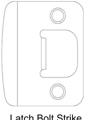
Latch Bolt Strike
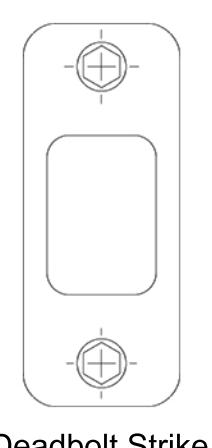
Deadbolt Strike
Deadbolt Armor Strike
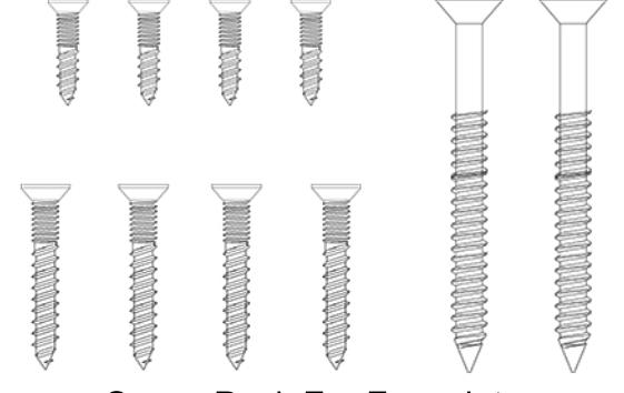
Screw Pack For Lock Assembly Screw Pack For Faceplate and Strike Installation
Getting Started

General Operation
This is an interconnect lock. Inside is always unlocked. Deadbolt can be extended from inside or outside by lifting lever or using thumbturn on the inside. From inside, rotating lever down will retract both bolts. From the outside, presenting a valid user code or keycard and rotating the lever down will retract both bolts. Outside latch bolt is always locked unless a valid code is used or unit is programmed to passage mode. Key Override - Rotating the key clockwise approximately 90o will allow you to rotate the lever and retract both bolts. The key will not retract the bolts. Return key back to home position to pull out key.
Tools Needed For Lock Installation
Phillips screw driver
Flat Head screw driver
Note:
Do not use a power drill for installation of lock as it can damage lock.
Tools May Be Needed For Door Preparation
Tape Measure
Power Drill (For drilling holes ONLY)
1" and 2 1/8" Drill Bits
Wood Chisel
Pencil
7/64 hex wrench
When batteries are installed and lock is ready to be operated, refer to programming guide for programming instruction.
Handing Information

Interconnect lock is handed. See handing information below.
Handing Information From Outside
If hinges are on the left, and door opens inward, it is a Left Hand Door(LH).
If hinges are on the left, and door opens outward, it is a Left Hand Reverse Door(LHR).
If hinges are on the right, and door opens inward, it is a Right Hand Door(RH).
If hinges are on the right, and door opens outward, it is a Right Hand Reverse Door(RHR).

If handing needs to be changed, see Addendum A (Page 19).
Door Preparation

Prepare door and jamb per template provided. Backset is adjustable for 2 ³⁄" or 2 ³⁄". The backset is the dimension from the edge of the door to centerline of the lock. This lock requires a 5 ¹⁄" center to center distance between the bore holes.
IMPORTANT:
Door stop is where the door will stop when normally operated. Door stop includes any gasket, smoke seal, or bumpers. Position of strikes are to be measured from where the door actually stops. The deadbolt, when thrown, cannot have any interference with the deadbolt strike. If there is any interference, strikes need to be adjusted for lock to work properly.

Latch installation - Latch handing and backset needs to match your door. See below for setting backset and handing.
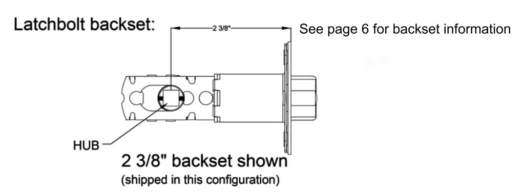

In order to adjust from 2 ³⁄" to 2 ³⁄", rotate hub on the diagonal as shown below. Pull on the hub to extend to 2 ³⁄" in the direction noted by the arrow. Push hub to the right to go back to 2 ³⁄".
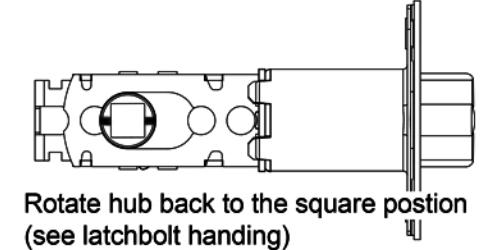

Latchbolt handing: See below showing the hub rotation for the handing of your door - RH, LH, RHR, LHR. See page 5 for door handing information.
8
Place the deadbolt in the door frame cutout and make sure the cross shaped hub is centered. Otherwise, look below on how to adjust the deadbolt by rotating the deadbolt face.
Extend deadbolt. Install deadbolt, and latch bolt as shown (RH Shown). Secure with 4 screws.
Position cross as shown below.

RH or RHR Lever Orientation

Scan QR code for a video on installing the outside lever
Install Outside Lever
1) Insert key and rotate cylinder 90° clockwise(CW).
Note: LH lever and RH lever orientation
2) Use a flat head screw driver to rotate slot in spindle 90° CW on outside assembly.
3) With key inserted and rotated 90° CW, push lever onto outside assembly while the slot is also rotated 90° CW. Lever catch is on underside of lever and it should snap into place. Rotate keyway back to home position and pull out key. Pull lever to make sure lever is secure.

Align outside lock assembly and install onto door face. Lever spindle goes through latch hub. Carefully guide wire harness through and over deadbolt housing.

Align backplate and install on the door. Guide the wire harness above the shelf on backplate and down through the slot. Secure top of backplate with 2 screws that go through the deadbolt housing - do not tighten until all screws on the backplate are installed. Secure bottom of backplate with 4 screws. Tighten all screws on backplate.

Install thumb turn spindle as shown. Plug in connector from lock assembly into plug on back of battery tray.
Set handing on battery tray. Push excess wire into hole over the backplate. Battery tray should sit flush without interference. Do not pinch wire harness. Secure battery tray with 6 screws.
Set handing on battery tray as shown below .
Note: Confirm the deadbolt is extended and

thumb turn spindle is installed. Scan QR code for a video on setting handing
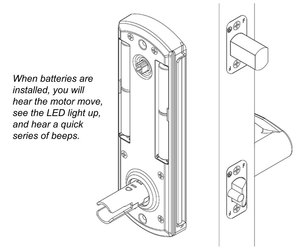
Install 4 AA-alkaline batteries into battery tray. Use only alkaline batteries for the interconnect lock.
When batteries are installed, you will hear the motor move, see the LED light up, and hear a quick series of beeps.

Place back cover over battery tray. Make sure the thumb turn on the back cover is oriented properly. Align thumb turn until it falls into place without forcing it. Secure back cover with 2 screws. Slide inside lever onto lock spindle. Lever catch is on underside of lever and it should snap into place. Pull lever to make sure it is secure.

Install deadbolt armor plate, deadbolt strike, and latch bolt strike. Secure with 6 screws.
Remember, the door stop is where the door will stop when normally operated. Stop includes any gasket, smoke seal, or bumpers. Position of strikes are to be measured from where the door actually stops. The deadbolt, when thrown, cannot have any interference with deadbolt strike. If there is any interference, strikes need to be adjusted for the lock to work properly.
IMPORTANT:
Make sure the lock operates properly before closing the door. From inside, lifting the lever should extend the deadbolt and rotating the lever down should retract both bolts. From outside, lifting the lever should extend the deadbolt. Wake up the keypad by swiping across the surface and enter 1-2-3-4-5-6-#. The LED will light red then green. Rotating the lever down should retract both bolts.
Addendum A

Changing the handing should not be needed. Lock is shipped with handing specified. See shipping confirmation or box for details.
If handing needs to be changed from Right Hand to Left Hand (Or Left Hand to Right Hand), handing must be changed on outside assembly. This entails changing a socket head screw on the back of outside assembly. Also, latch bolt and levers need to be adjusted.
See:
Addendum C To change handing on outside assembly Addendum B To remove and adjust levers Step 2 To adjust latch bolt
If handing needs to be changed from Right Hand to Right Hand Reverse (Or Left Hand to Left Hand Reverse), only the latch bolt orientation needs to be changed.
See:
Step 2 In order to adjust latch bolt
Addendum B

Remove Inside Lever
- 1) Insert prong on lever removal tool in the hole on underside of the lever.
- 2) Lift up the lever removal tool to depress the lever catch and pull the lever off.
Remove Outside Lever
1) Insert the mechanical key and rotate it 90° clockwise.

3) Lift up the lever removal tool to depress the lever catch and pull the lever off.

Addendum C

Change Handing On Outside Assembly
For this example, we will be changing the handing of a right hand lock to a left hand lock .
1) Remove lock assembly from door.
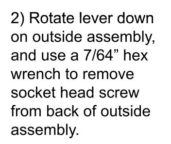
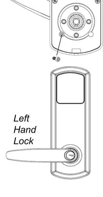
2) Rotate lever down on outside assembly, and use a 7/64" hex wrench to remove socket head screw from back of outside assembly.
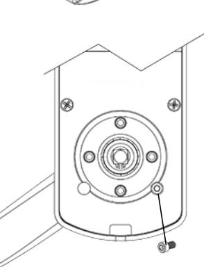
3) To change handing, rotate lever up and install socket head screw on the left side of lock assembly.

Note: Be sure to change lever to new handing. See Install Outside Lever for more information.

Scan QR code for a video on changing handing
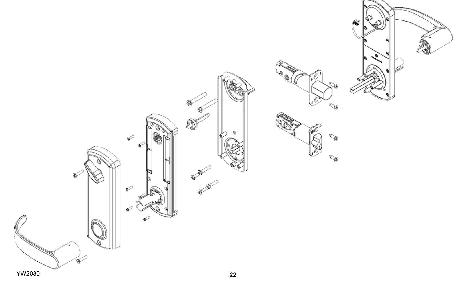
Exploded View Of Lock


| PROBLEM | CAUSE | SOLUTION |
|---|---|---|
| Keypaddoesnotlightup. | Batteriesaredead. | Replacebatteriesbyremovingbackcover. |
|
Keypadislockedoutduetoxamountofincorrect
codes. |
Wait60secondsandtryagain. | |
| Notfullypluggedinwiresorpinchedwires. | Checkwireconnection. | |
|
Latchboltretractswhenleverisrotated
up,notdown. |
Hubonlatchboltwasnotinstalled
correctly. |
Takelockoffdoorandre-adjustlatchbolt.
(SeeStep2) |
|
Rotatingoutsideleverupwillnotextend
deadbolt. |
Deadboltwasnotextendedduring
installation. |
Removeinsidelever,backcover,and
batterytrayextenddeadboltandre-install parts.(SeeStep8) |
|
Handingonoutsideassemblywasnot
properlyset |
Takelockoffdoor.Adjusthandingonoutside
assemblyandre-installparts.(SeeAddendumC) |
|
|
Keywillnotcomeoutofleverafter
installation. |
Keycylinderwasnotinstalledcorrectly. |
Useleverremovaltooltoremoveleverand
re-installcylindercorrectly.(SeeStep5) |
|
Outsideleverretractsdeadboltandlatch
boltwithoutakey,usercodeorkeycard. |
Handingonoutsideassemblywasnot
properlyset. |
Takelockoffdoor.Adjusthandingonoutside
assemblyandre-installparts.(SeeAddendumC) |
| Deadboltbindsordoesnotfullyextend. | Strikesarenotaligned. | Adjuststrikes.(SeeStep12) |
VISITWWW.TOWNSTEEL.COMFORMOREINFORMATION.
17901RAILROADSTREET CITYOFINDUSTRY,CA91748 TOLLFREE:877-858-0888
TEL:626-965-8917 FAX:626-965-8919