


IMPORTANT

Templates must be printed without size modifications and verified for dimensional accuracy.
- • Before printing, select the printing options necessary to ensure that copies are produced without size adjustments.
- • After printing, measure the dimensions indicated on the template to ensure correct scale.
ET-PDLN
Networx Trilogy® Panic Exit Device Trim
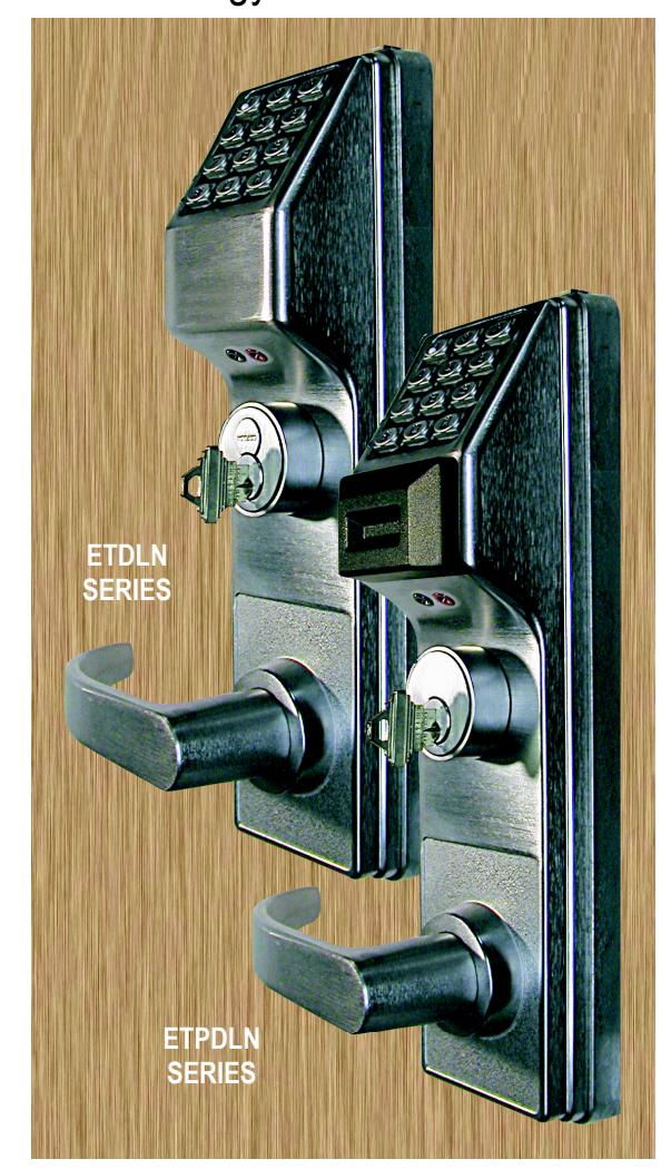
Corbin/Russwin Model ED5000
INSTRUCTIONS & TEMPLATE
1. Existing Installation: Remove Exit device from door.
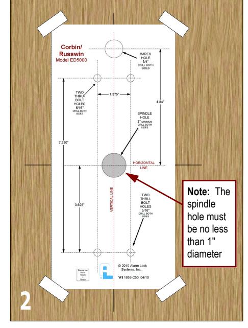
2. Existing Installation: Position Alarm Lock template on horizontal & vertical lines of existing spindle hole.
New Installation: Locate and mark horizontal and vertical lines indicated in Exit Device Instructions/Template. Line up Alarm Lock template with horizontal and vertical lines and tape onto door.
Existing and New Installations: Mark all hole centers on each side of door. Drill all holes from both sides of door to avoid splintering.

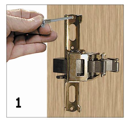
3. Before positioning the Exterior assembly on door, feed the ribbon cable and the green ground wire (with ring connector) through the 3/4" wire hole.

4. Replace Exit Device, insert and fasten with 4 new mounting screws (do not over-tighten). Before mounting the Battery Box Mounting Plate, carefully pull wires from door through center of Plate. Do not pinch or cut wires. Position the Plate a minimum of 1/4" above Exit Device. Fasten the Battery Box Mounting Plate with four #8 x 3/4" flat head combination screws, using one of the screws to secure the green ground wire ring connector to the Plate.

5. Connect the Battery Pack (batteries may be shrink wrapped as shown or may be inside a housing) and place inside of Battery Box Mounting Plate. Secure the Battery Pack inside the Battery Box Cover with the hook and loop fastener (provided). Position the Cover and fasten with four #6-32 x 5/16" screws.

6. Replace and fasten exit device & battery box covers.
Check lock for proper operation before closing door.
Rim Exit Device
To Change Cylinder
When replacing cylinder be sure to use the proper Cylinder Adapter and Tailpiece.

Alarm Lock Systems, Inc.
A division of the NAPCO Security Technologies, Inc. 345 Bayview Avenue, Amityville, NY 11701 Tel: (631) 789-4871 Fax: (631) 789-3383
www.alarmlock.com Publicly traded on NASDAQ Symbol: NSSC

and remove cylinder screws. B. Remove old cylinder and insert new cylinder. C. Note: The tailpiece must be in the

horizontal position as shown in the image above.
