


INSTALLATION INSTRUCTIONS for WS707AKM and WS708AKM MULLIONS

FM280 2/08 (617417815)
Tools Required:
Tape Measure Pencil #3 Phillips Head Screw Driver Hammer Punch #7 Drill and 1/4"-20 Tap 3/8" concrete drill
5/64" Allen Wrench 3/16" Allen Wrench
1/2" drill
ATTENTION: Before starting the installation make sure that:
- You have the correct product;
- Doors are properly installed and hinge screws are secure.
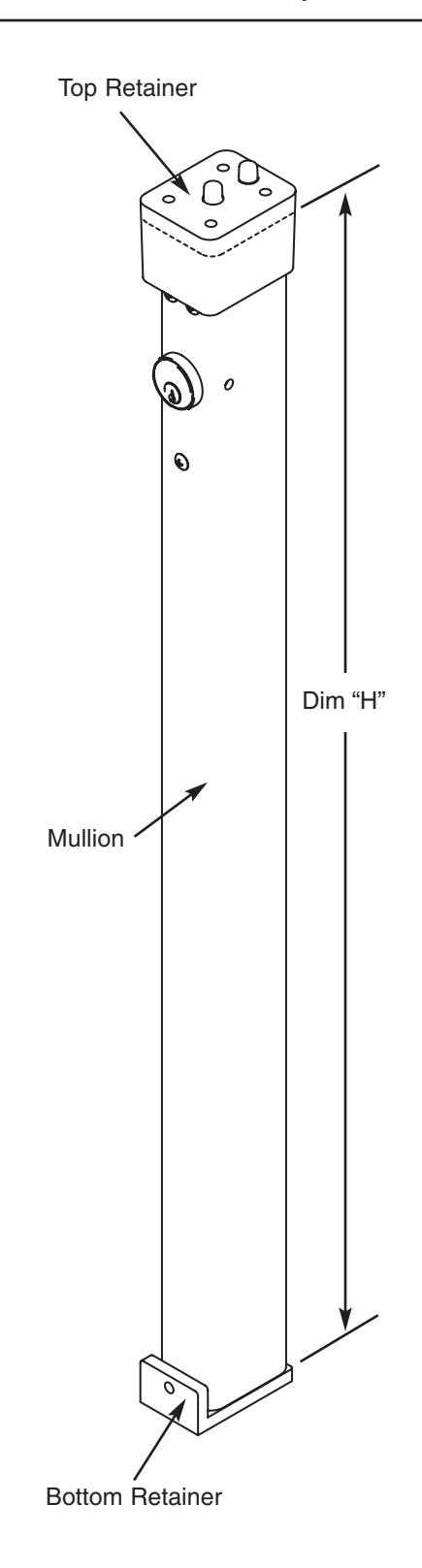
1. Attach the Top Retainer to the top jamb
- a. Mark the centerline of the Top Retainer on the top jamb.
- b. Close the doors and keep door leaves tight to the stops.
- c. Fold the supplied Template No. FM281 along the creased line and locate it on the top jamb using the centerline marked. Attach it to the frame and doors with the self-adhesive strips supplied.
- d. Mark, drill and tap holes required.
- e. Install the Top Retainer using (4) 1/4-20 x 5/8" flat head screws.
- 2. Locate the Bottom Retainer on the floor
ATTENTION:
Do NOT attach the Retainer to the floor at this point
3. Cut the Mullion to size
- a. Measure the distance (H) between the inside surface of the Top Retainer and the top of the Bottom Retainer surface as shown.
- b. Cut off bottom of the Mullion to desired length (L), using the following formula: L = H - 1/16"
- 4. Position the Mullion into the Bottom and Top Retainers and locate it vertically. Mark the Bottom Retainer location on the floor (Bottom Retainer still free to move)
ATTENTION:
Make sure that the Mullion surface is engaged with the doors and Mullion is plumb to door face and frame.
5. Install the Bottom Retainer
- a. Remove the Mullion from the retainers and put it aside.
- b. Align Bottom Retainer with previous markings from Step 4.
- c. Use a punch and hammer to mark hole locations on floor.
- d. Drill (2) 3/8" diameter holes in floor to a min. depth of 2 5/8"
- e. Mount the Bottom Retainer to the floor with supplied (2) 3/8" fasteners
INSTALLATION INSTRUCTIONS for WS707AKM and WS708AKM MULLIONS

FM280 2/08 (617417815)
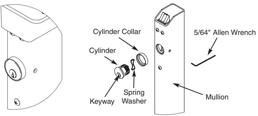
6. Installation of Cylinder
- a. Depress latchbolt and hold fully retracted.
- b. Carefully thread Cylinder with Cylinder Collar and Spring Washer into lock assembly until it bottoms out.
- c. Unscrew the Cylinder orienting keyway at bottom.
- d. Release latch bolt. Note: If latch bolt is not fully projected loosen Cylinder an additional 1-2 full turns.
- e. Tighten set screw with 5/64" Allen Wrench through access hole in side of Mullion.
- f. Check operation of Cylinder and lock assembly. Note : Key only turns counter-clockwise.
7. Install the Mullion
- a. Place Mullion onto Bottom Retainer and pivot into opening, to latch.
- b. Tighten Bottom Retainer set screw with 3/16" Allen Wrench to prevent Mullion rattle.
- 8. Install exit devices according to manufacturer's instructions
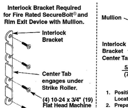
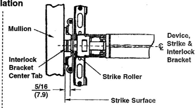
9. Fire rated Rim and SecureBolt® Exit Devices:
After exit devices and strikes have been assembled, install Interlock Brackets with (4) #10-24 x 3/4" screws as shown in illustration below.
Corbin Russwin, Inc. 225 Episcopal Road Berlin, CT 06037-4004 www.corbinrusswin.com
Technical Product Support
Phone: 888-607-5703 Fax: 800-659-7293
Canada: ASSA ABLOY DSS Canada 160 Four Valley Drive Vaughan, Ontario L4K 4T9 www.assaabloycanadadss.ca
Copyright © 2008 Corbin Russwin, Inc. All rights reserved. Reproduction in whole or in part without the express written permission of Corbin Russwin, Inc. is prohibited.
2