
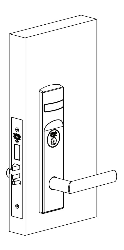
Used with VN Escutcheon Trim and V Series Indicators

This product can expose you to lead which is known to the state of California to cause cancer and birth defects or other reproductive harm. For more information go to www.P65warnings.ca.gov.
WARNING
Attention Installer: Improper installation may result in damage to the product and void the factory warranty.
Used with VN Escutcheon Trim and V Series Indicators

Installation Instructions
| TOC | Table of Contents | |
|---|---|---|
| 1 |
Tools Required
3 |
|
| 2 | Indicator Variants3 | |
| 3 |
Mortise Lock Handing
4 |
|
| 4 | Rehanding Indicator (if required)5 | |
| 5 | Installation6 | |
| a | Prepare Door6 | |
| b |
Install Strike and Lock
6 |
|
| c |
Install Outside Trim (for standard levers or knobs only)
6 |
|
| d | Install Inside Trim (for standard levers or knobs only)6 | |
| e | Install Levers (for standard levers or knobs only)7 | |
| f | Attach Levers to Escutcheons (for Muséo® levers only)7 | |
| g | Install Outside Trim (for Muséo® levers only)8 | |
| h | Install Inside Trim (for Muséo® levers only)8 | |
| i |
Install Cylinder
9 |
|
| j | Install Outside Front9 | |
| k | Perform Functional Check9 | |
| 6 | Indicator Parts 10 |
Used with VN Escutcheon Trim and V Series Indicators
Installation Instructions

1 Tools Required
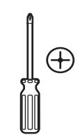
#1, #2 & #3 Phillips head screwdrivers
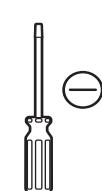
Flat blade screwdriver
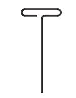
Allen wrench:


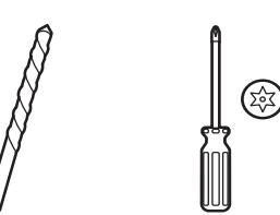
3/8" Drill bit T-20 Torx Screw with Tamper Pin Driver
For installation assistance contact Corbin Russwin
2 Indicator Variants
Depending on function and option ordered, indicators are provided in the following variations. These instructions detail how to install with cylinder, however other variations follow similar instructions. (Figure 1)
Contact factory with questions.
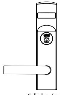
Cylinder – For installation on inside or outside of door.
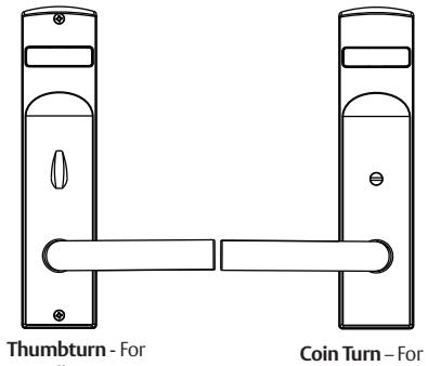
installation on outside of door. installation on inside of door.
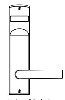
No input/blank - For installation on inside of door.
Used with VN Escutcheon Trim and V Series Indicators
Installation Instructions

3 Mortise Lock Handing
- 1. Move red locking screw to side of lock body being locked.
- 2. Push in latch. Depress catch plate with screwdriver. (Figure 2)
- 3. Pull latch out of lock body and turn latch over. (Figure 3)
- 4. Push in latch while holding screwdriver behind latch tail. (Figure 5)
Note:
Ensure that latch is pushed in until catch plate is no longer depressed. (Figure 4)
5. Rotate lock front to match bevel of door, as shown. (Figure 6)
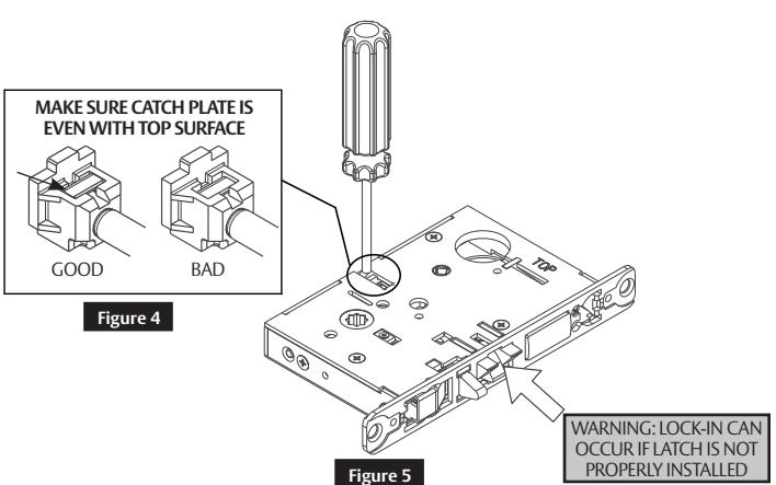

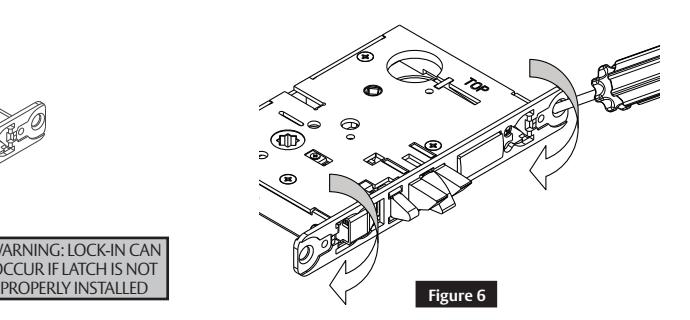
Figure 3
Used with VN Escutcheon Trim and V Series Indicators
Installation Instructions

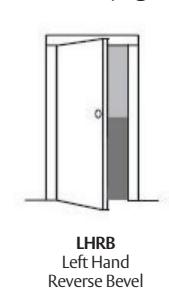
4 Rehanding Indicator (if required)
Verify hand and bevel of door. (Figure 7)
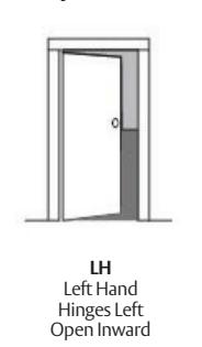
Hinges Left Open Outward
Figure 7
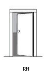
Right Hand Hinges Right Open Inward

RHRB Right Hand Reverse Bevel Hinges Right Open Outward
Scan this QR code for the Corbin Russwin Indicator Handing Charts
Note:
Stand outside of locked door when determining door hand.
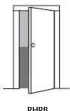
Next, verify inside and/or outside indicators are handed correctly, using Spindle Cam Position chart. (Figure 8) If they are handed correctly, skip to Step 5a Prepare Door. If they are not handed correctly:
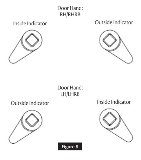
- 1. Remove indicator back plate by pulling out from top slot, then remove spindle cam from assembly. (Figure 9)
-
2. Position spindle cam in correct direction for door hand. (Figure 8)
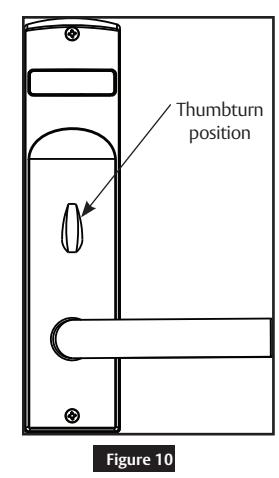
- Important: For thumbturn indicators, make sure thumbturn is positioned in the 12 o'clock direction as shown. (Figure 10)
- 3. Slide spindle cam post into correct slot of display slide. (Figure 9)
- 4. Re-seat back plate into original position.
- 5. Return indicator to the vacant/unlocked position for installation.
Spindle Cam Position
5
Used with VN Escutcheon Trim and V Series Indicators
Installation Instructions

5 Installation
a Prepare Door
Prepare door for function holes, size, and location according to FM500 door marker template, if not already prepped.
b Install Strike and Lock
- 1. Install strike using two (2) 3/4" combination mounting screws. If strike box is needed, insert between strike and door frame. (Figure 11)
- 2. Make sure handing of lock matches handing of door.
- 3. Insert mortise lock into door, and temporarily hand tighten two (2) 1" combination screws. (Figure 12)
Notes:
- Keep door open until installation is complete.
- Make sure lock is unlocked. If lock has a toggle, push bottom of toggle inward to ensure it is unlocked during installation.
Figure 11 Narrower Hole 3/4" Screws Lock 1" Screws
Figure 12
Control Hub
Strike Orientation Strike
Wider Hole
c Install Outside Trim (for standard levers or knobs only)
For Muséo® Levers, skip to step 5f Attach Levers to Escutcheons (for Muséo® levers or knobs only) on page 7.
- 1. Verify the indicator is in the vacant/unlocked position.
- 2. Align trim posts with vertical holes in door. (Figure 13)
- 3. Slide outside escutcheon assembly through lock body from outside door face.
Note:
If indicator is used on the outside, align hub indicator spindle with diamond hole in control hub of lock. (Figure 14)
Outside Escutcheon Assembly Figure 13 Figure 14
d Install Inside Trim (for standard levers or knobs only)
- 1. Verify the indicator is in the vacant/unlocked position.
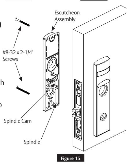
- 2. Align escutcheon and install inside escutcheon assembly onto inside of door face. (Figure 15)
Note:
If indicator is used on the inside, align hub indicator spindle with diamond hole in control hub of lock. (Figure 14)
3. Through-bolt inside escutcheon to outside escutcheon with two (2) #8-32 x 2-1/4" screws.
Note:
Screw heads should be visible on inside escutcheon.
FM521 11/21
Used with VN Escutcheon Trim and V Series Indicators
Installation Instructions

5 Installation (cont.)
e Install Levers (for standard levers or knobs only)
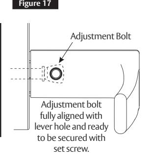
- 1. Install outside lever or knob by inserting adjustment bolt on opposite side of door. Tighten bolt finger-tight and loosen a few turns. (Figure 17)
- 2. Install inside lever or knob by inserting dowel screw.
Notes:
- Use correct spindle orientation. (Figure 16)
- Make sure adjustment bolt hole is aligned with lever or knob hole. (Figure 18)
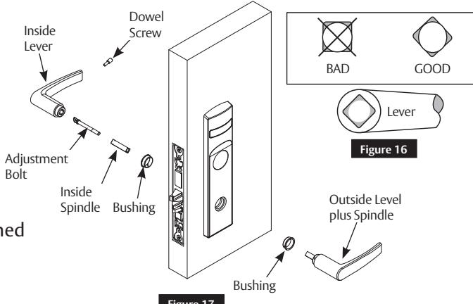
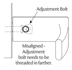
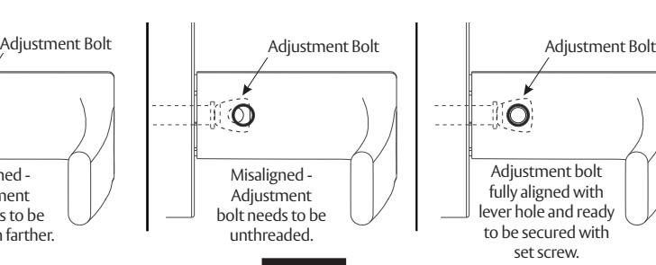
Figure 18
f Attach Levers to Escutcheons (for Muséo ® levers only)
For Standard levers, skip to Step 5i Install Cylinder on page 9.
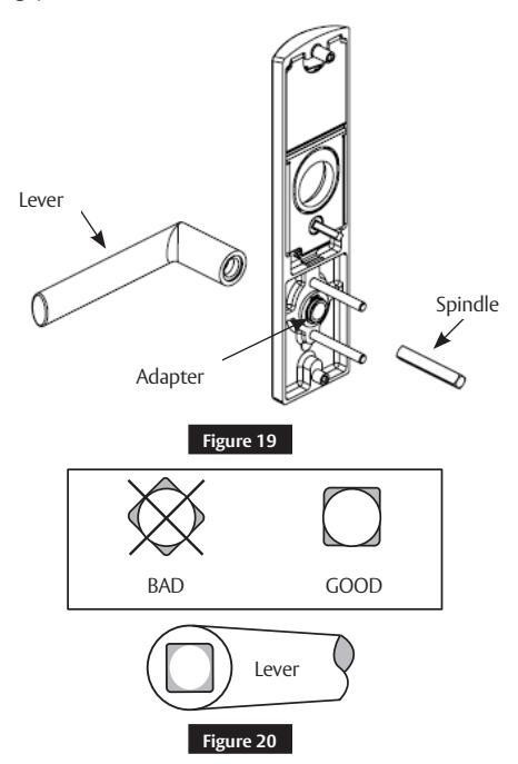
- 1. Thread lever onto adapter. (Figure 19)
- 2. Insert spindle into adapter and fully tighten onto lever. Loosen smallest amount that allows spindle to engage lever.
- 3. Verify correct spindle orientation with lever held horizontally. (Figure 20)
Note:
Must attach Muséo® Levers to both outside and inside escutcheon.
Used with VN Escutcheon Trim and V Series Indicators
Installation Instructions

5 Installation (cont.)
g Install Outside Trim (for Muséo ® levers only)
- 1. Verify the indicator is in the vacant/unlocked position.
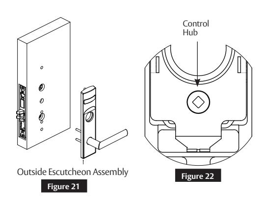
- 2. Align trim posts with vertical holes in door, and be sure lever is horizontal. (Figure 21)
- 3. Slide outside escutcheon assembly through lock body from outside door face.
Note:
If indicator is used on the outside, align hub indicator spindle with diamond hole in control hub of lock. (Figure 22)

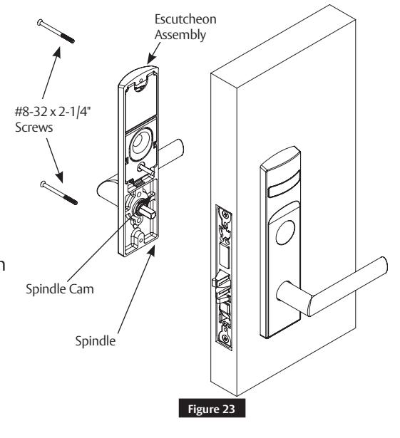
h Install Inside Trim (for Muséo ® levers only)
- 1. Verify the indicator is in the vacant/unlocked position.
- 2. Align escutcheon, and be sure lever is horizontal. (Figure 23)
- 3. Install inside escutcheon assembly onto inside of door face.
Note:
If indicator is used on the inside, align hub indicator spindle with diamond hole in control hub of lock. (Figure 22)
4. Through-bolt inside escutcheon to outside escutcheon with two (2) #8-32 x 2-1/4" screws.
Note:
Screw heads should be visible on inside escutcheon.
Used with VN Escutcheon Trim and V Series Indicators
Installation Instructions

5 Installation (cont.)
i Install Cylinder
-
1. Thread cylinder into lock until flush with escutcheon surface. (Figure 24)
- Pull key slightly out of cylinder to help thread into lock body.
-
2. Install cylinder clamp screw with a #1 Phillips screwdriver.
- Check operation, and adjust cylinder if necessary.
Notes:
- Corbin Russwin logo must be horizontal and on top. (Figure 25)
- If double cylinder function is used, repeat steps 1 and 2 for second cylinder.
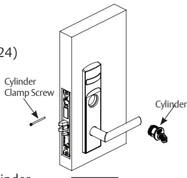
Figure 24
Correct
Key and cylinder must be rotated as shown.
Incorrect
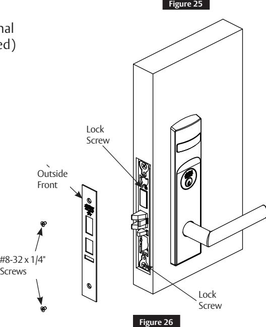
j Install Outside Front
- 1. Tighten the two (2) lock screws completely. (Figure 26)
- 2. Attach outside front with two (2) flat head screws #8-32 x 1/4".
k Perform Functional Check
DO NOT FORCE if resistance is encountered during functional check. Refer back to Rehanding Indicator section (if required) to ensure correct handing. Rehand if necessary.
-
1. Insert key into cylinder (if present) and rotate.
- Ensure there is no friction against lock case or any other obstructions.
-
2. Check key retracts latch.
- Key should rotate freely.
-
3. Throw deadbolt (if present).
- Check key retracts both deadbolt and latch.
-
4. Test levers.
- Confirm latch and deadbolt (if installed) retract.
- 5. Verify indicator displays correct status when locked and unlocked.
Used with VN Escutcheon Trim and V Series Indicators
Installation Instructions

6 Indicator Parts
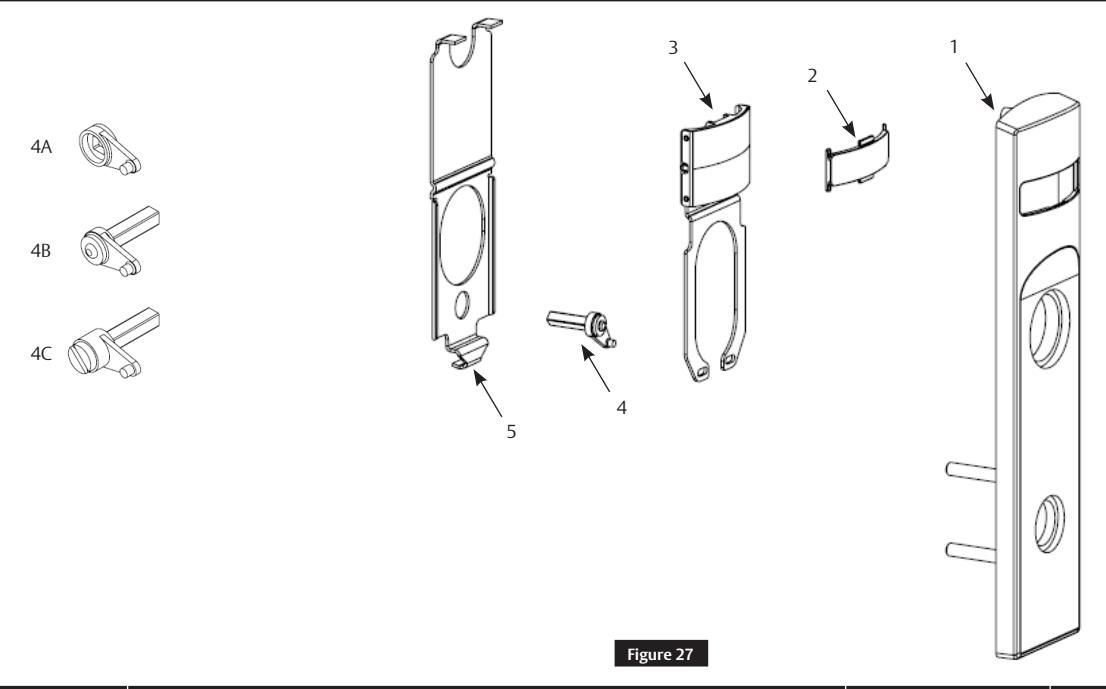
| Figure 27 | Description | Part Number | Required |
|---|---|---|---|
| 1 | VN Indicator Escutcheon | Consult Factory | 1 |
| 2 | Indicator Window | 856F049 | 1 |
| Indicator Display Assembly – Green 'Unlocked' / Red 'Locked' | 858F241 | 1 | |
| Indicator Display Assembly – Green ' Vacant' / Red 'Occupied' | 858F251 | ||
|
Indicator Display Assembly – Green Unlocked Icon / Red Locked
Icon |
858F261 | ||
| 3 | Indicator Display Assembly – White 'Unlocked' / Red 'Locked' | 858F271 | |
| Indicator Display Assembly – White ' Vacant' / Red 'Occupied' | 858F281 | ||
|
Indicator Display Assembly – White Unlocked Icon / Red Locked
Icon |
858F291 | ||
| 4A | Indicator Spindle Cam – Thumbturn | 855F619 | 1 |
| 4B | Indicator Spindle Cam – Cylinder / No Input/Blank | 855F707* | 1 |
| 4C | Indicator Spindle Cam – Coin Turn | 855F747* | 1 |
| 5 | Indicator Escutcheon Back Plate | 855F638 | 1 |
| 6 | VN Escutcheon Screw Pack (Not shown) | 858F517 x finish* | 1 |
| 7 | Door Marker Template (Not shown) | FM500 | 1 |
* These parts are for 1-3/4" standard thickness doors. For other thicknesses, please consult factory.
Note:
Reference ML2000 parts manual for all lock body parts.
For installation assistance contact Corbin Russwin
whole or in part without the express written permission of ASSA ABLOY Access and Egress Hardware Group, Inc. is prohibited.
Used with VN Escutcheon Trim and V Series Indicators
Installation Instructions