


TL3700 Series
Tubular Lockset

This product can expose you to lead which is known to the state of California to cause cancer and birth defects or other reproductive harm. For more information go to www.P65warnings.ca.gov.
TL3700 Series
Tubular Lockset
Installation Instructions

| TOC | Table of Contents | |
|---|---|---|
| 1 | Tools Required 2 | |
| 2 | Package Contents 3 | |
| 3 | Door Preparation 4 | |
| a | Mark and Drill Holes 4 | |
| b | Final Door Preparation 4 | |
| c | Frame Preparation for Strike 4 | |
| 4 | Latch, Lock, and Trim 5 | |
| a | Latch Installation 5 | |
| b | Lock and Trim Installation5 | |
| 5 | Dummy Trim (TL3750/TL3770) 6 | |
| a | Package Contents 6 | |
| 6 | Square Rose 6 | |
| a | Tools Required for Assembly 6 | |
| b | Package Contents 7 | |
| c | Installation 7 |
1 Tools Required
- #2 Phillips Screwdriver
- 3/32" Hex Wrench
- 1/8" Drill Bit
- 2-1/8" Bore
- 1" Bore
TL3700 Series
Tubular Lockset
For installation assistance contact Corbin Russwin
Installation Instructions

Package Contents
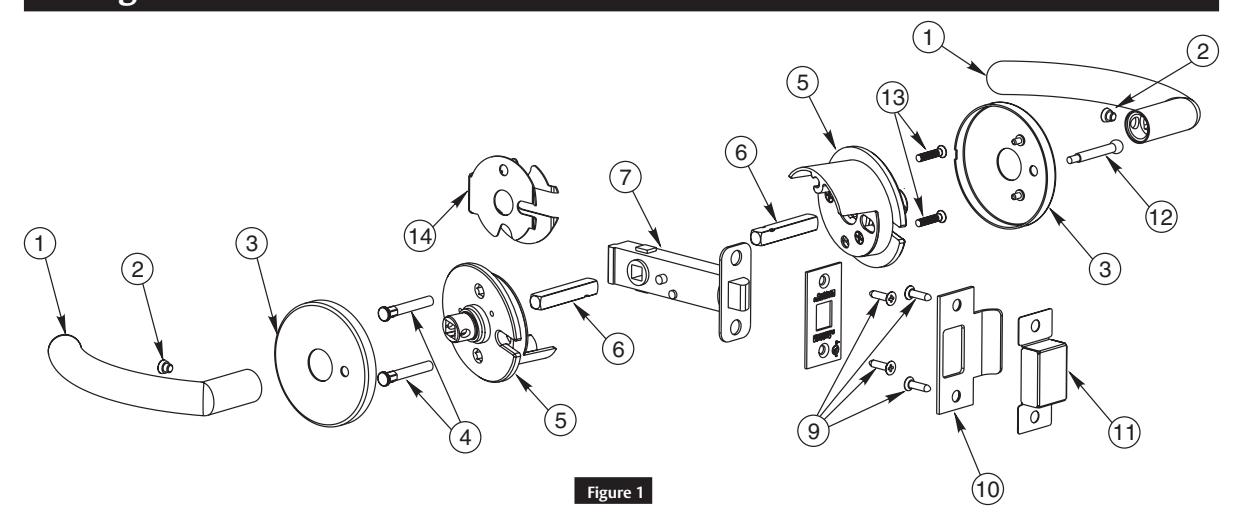
| Figure 1 | Description | Req. |
|---|---|---|
| 1 | Lever | (2) |
| 2 | Set Screw | (2) |
| 3 | Rose | (2) |
| 4 | Mounting Post | (2) |
| 5 | Spring Housing | (2) |
| 6 | Spindle | (2) |
| 7 | Latch | (1) |
| 8 | Faceplate | (1) |
| 9 | Screws-Latch & Strike #8-32 x 3/4" | (4) |
| 10 | Strike | (1) |
| 11 | Strike Box | (1) |
| 12 | Push Button (TL3720 only) | (1) |
| 13 | Mounting Post Screw | (2) |
| 14 | Fire Guard Clip (Fire Rated option only) | (1) |

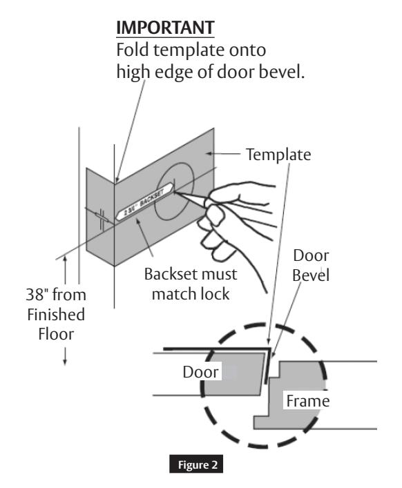
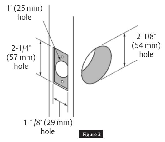
3 Door Preparation
a Mark and Drill Holes
b Final Door Preparation
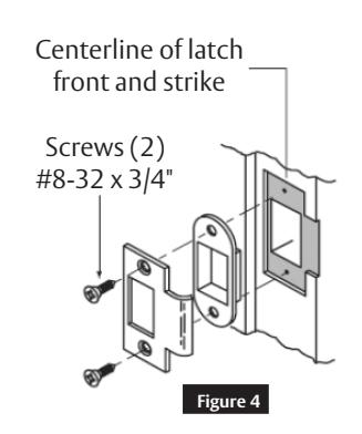
c Frame Preparation for Strike
For installation assistance contact Corbin Russwin

4 Latch, Lock, and Trim
a Latch Installation 1
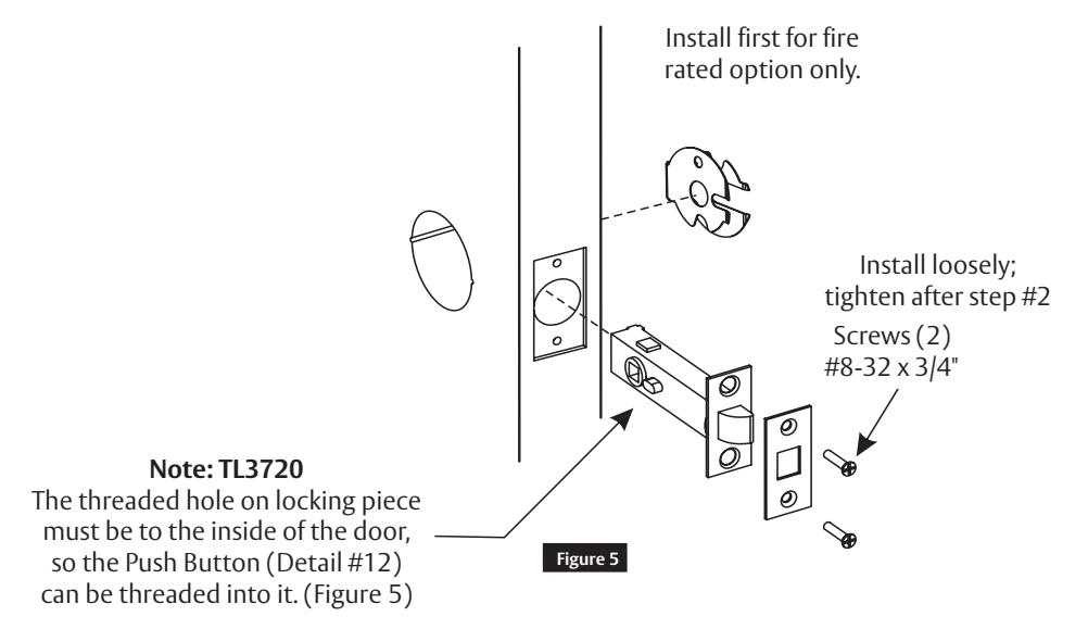
b Lock and Trim Installation
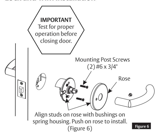
Note: Rose to be removed with a flat head screwdriver at notch.
For installation assistance contact Corbin Russwin

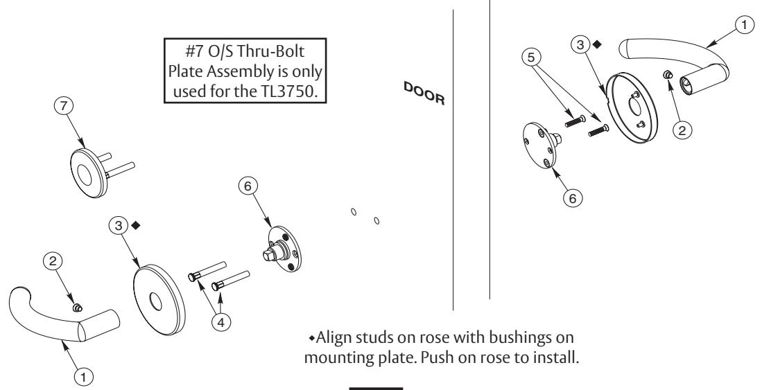
5 Dummy Trim (TL3750/TL3770)
a Package Contents
Note
Only (2) door prep holes are required for Dummy Trim. See door marker supplied in box for further details. ( Figure 7)
4 Figure 7
| Figure 1 |
1
Description |
Req. |
|---|---|---|
| 1 | Lever | (2) |
| 2 | Set Screw | (2) |
| 3 | Rose Assembly | (2) |
| 4 | Mounting Post | (2) |
| 5 | Mounting Post Screw | (2) |
| 6 | Mounting Plate Assembly | (2) |
| O/S Thru-Bolt Plate Assembly | ||
| 7 | TL3750 only | (1) |
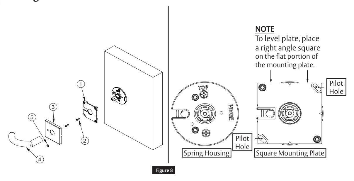
6 Square Rose
a Tools Required for Assembly
- • Drill
- Pilot Bit
- Phillips Screwdriver
- Right Angle Square

b Package Contents
| Figure 1 | Description | Req. |
|---|---|---|
| 1 | Lever | (2) |
| 2 | Set Screw | (2) |
| 3 | Rose Assembly | (2) |
| 4 | Mounting Post | (2) |
| 5 | Mounting Post Screw | (2) |
| 6 | Mounting Plate Assembly | (2) |
| O/S Thru-Bolt Plate Assembly | ||
| 7 | TL3750 only | (1) |
6 Square Rose (cont.)
c Installation
-
1. Install lock per instructions starting on page 5.
- a. Square rose installation begins after spring housing installation.
- 2. Position square mounting plate over spring housing as seen in Figure 1.
- 3. Drill two centered pilot holes for the #6 mounting screws in the upper right and lower left portions of the square mounting plate.
- 4. Loosely attach mounting plate to both sides of the door with screws.
-
5. Square top surface of mounting plate to edge of door.
- NOTE: The square edge MUST be on the flat surface of the square mounting plate for proper leveling.
- 6. Tighten mounting screws.
- 7. Press rose onto mounting plate, fasten lever with set screw.

Corbin Russwin, Inc. 225 Episcopal Road Berlin, CT 06037 USA Phone: 800-543-3658 Fax: 800-447-6714 www.corbinrusswin.com