


Metal, Wood or Composite Doors
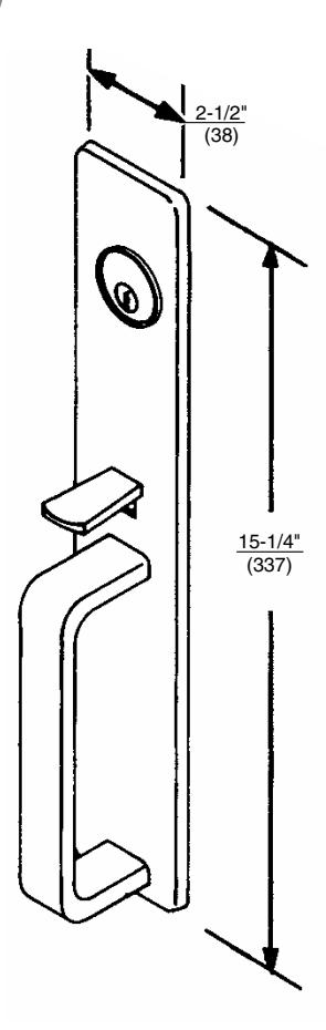
(F05) Classroom Function (F06) Storeroom Function
Installation Instructions
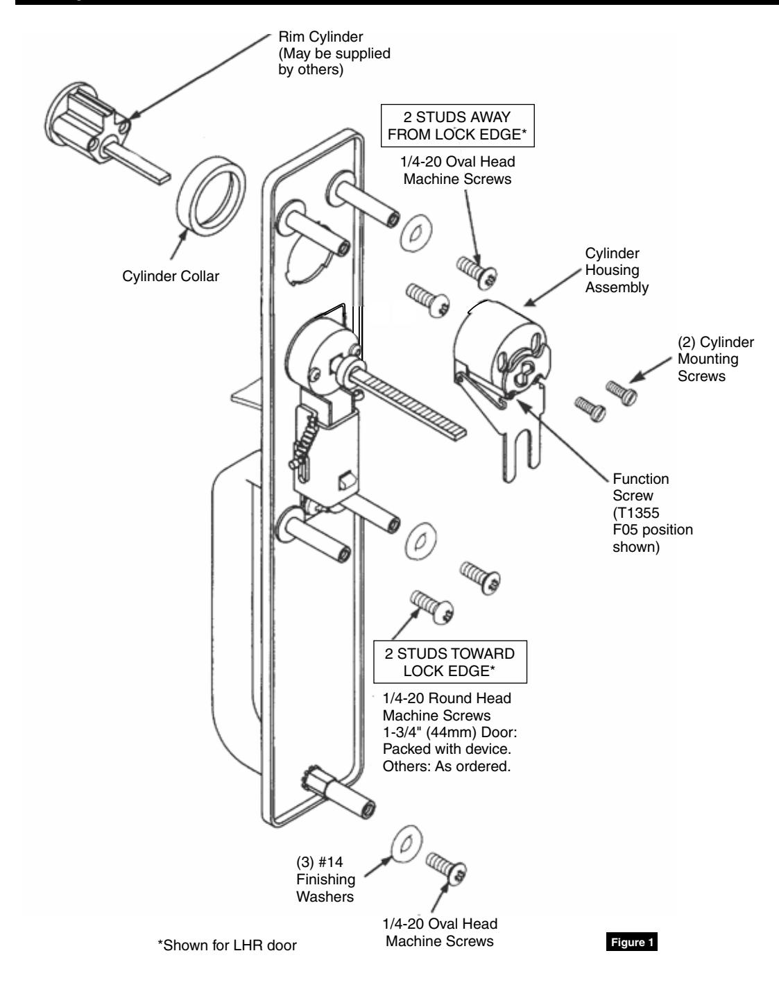
1 Components
Installation Instructions
2 Trim Assembly
1. Check cylinder components.
NOTE: Non-standard cylinders may require special collars.
- 2. Assemble cylinder. Insert cylinder housing prongs into matching notches of escutcheon. Pass cylinder tailpiece through cylinder collar and slot in cylinder housing cam. Bolt cylinder seated in cylinder collar recess. Do not overtighten screws.
- 3. Check cylinder action. Cylinder must freely rotate tailpiece into lock (cam pushing locking lever down) and unlock positions. When locking lever is engaged, it depresses trim spindle. Thumbpiece handle is, thus, disengaged from spindle.
- 4. Cut cylinder tailpiece. Correct length is 1/16" to 3/16" (2 to 5mm) beyond cylinder housing cam.
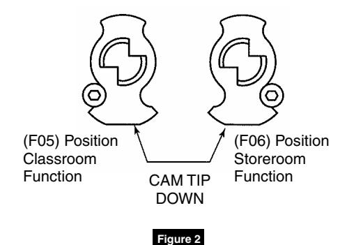
- 5. Determine trim function. T1355 (as packed): Classroom Function (F05) Key locks/unlocks thumbpiece. Key removable in locked and unlocked positions.
Field convertible to Storeroom Function (F06): Key locks/unlocks thumbpiece. Key removable ONLY in locked position.
6. To change trim function: Rotate cam tip to down position (locked mode). Move function screw as shown. (Figure 2)
Installation Instructions
3 Installation
- 1. Assemble trim. (Figure 1)
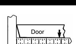
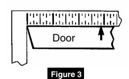
- 2. After marking door inside face for device location (Device Instructions), transfer "Vertical Reference Centerline" from inside to outside door face. (Figure 3)
- 3. Transfer "Horizontal Reference Centerline" from inside to outside door face.
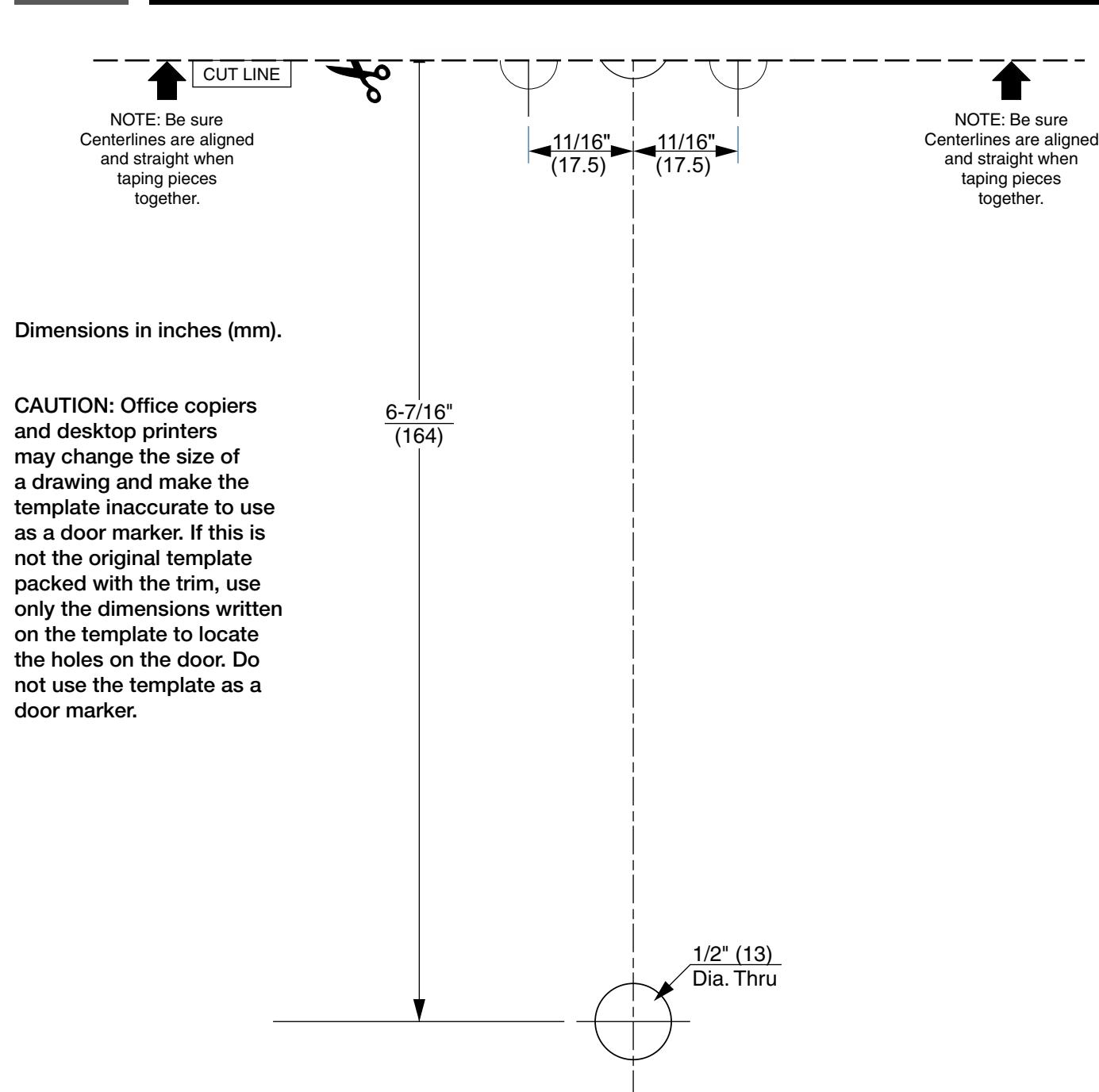
- 4. Align trim template and tape to outside door face. (pages 6 and 7)
- 5. Spot holes and prepare door for trim.
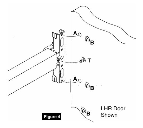
- 6. Mount trim to door. Fasten, finger tight only, with two (2) screws and washers seating on door as shown, plus one (1) engaged to pull bottom stud. (Figure 4)
NOTE:
- Device is bolted to trim using holes "A" (closest to door lock edge).
- Tailpiece "T" gets into horizontal or vertical cam slot.
- Screws and washers bolt trim to door using holes "B".
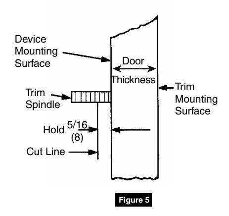
- 7. Cut trim spindle as shown. (Figure 5)
NOTE:
- Measure from device mounting surface (door face or shim surface).
- Trim must be unlocked (tailpiece turning when thumbpiece is depressed).
- 8. Seat device so that trim tailpiece penetrates cam slot, as shown. (Figure 4) Continue as shown in device instructions.
Installation Instructions
4 Template Top CAUTION: Office copiers and desktop printers may change the size of a drawing and make the template inaccurate to use as a door marker. If this is not the original template packed with the trim, use only the dimensions written on the template to locate the holes on the door. Do not use the template as a door marker. Dimensions in inches (mm). *Wood fire labeled doors require factory prep. See Corbin Russwin Template Book. 11/16" (17.5) 11/16" (17.5) 3-5/8" (92) 3-5/8" (92) 3-1/4" (83) *1-1/4" (32) Rectangular Deep Cutout 1/2" (13) Dia. Thru CL HORIZONTAL REFERENCE (DEVICE AND TRIM) CL VERTICAL REFERENCE (TRIM) DOOR OUTSIDE FACE Pair arrows with "template bottom" arrows and tape along Tape Line to assemble complete door marker. Pair arrows with "template bottom" arrows and tape along Tape Line to assemble complete door marker. 3/8" (10) Dia Thru (5 Places) 1-1/2" (38) 3-1/2" (89) 1/2" (13) Dia. Thru 1/8" (3) Deep 2-7/8" (73)
TAPE LINE
Installation Instructions

This page intentionally left blank for template use.
Installation Instructions
5 Template Bottom

Corbin Russwin 225 Episcopal Road Berlin, CT 06037 Phone: 800-543-3658 Fax: 800-447-6714 corbinrusswin.com
Copyright © 2018 Corbin Russwin, Inc., an ASSA ABLOY Group company. All rights reserved. Reproduction in whole or in part without the express written permission of Corbin Russwin, Inc. is prohibited.