


744F688
For additional information or assistance, contact Corbin Russwin at 888-607-5703 or www.corbinrusswin.com

Thermal Pin Installation Instructions for
For use on 5000 Series -ED5470B SVR and ED5860B CVR Fire Rated Doors with Less Bottom Rod (M55).

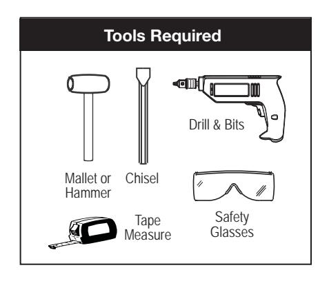
NOTES:
- This device is designed to be installed horizontally between door leafs or vertically between door leaf and fi nished fl oor.
- This device may be installed on single or double doors.
- Extreme heat will activate this device.
- Install door(s) per the manufactures' instructions. The doors should be square and plumb and have the correct gaps between the door(s) and fi nished fl oor.
- Note dimensions on fi gures to ensure correct location of pin and cap. Figures not to scale. Dimensions are given in inches(") and millimeters(mm).
For Horizontal Installation Between Door Leafs:
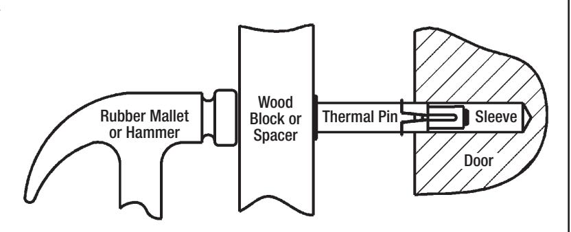
- 1. Drill 5/8"(16) diameter hole as shown in "Active" leaf of door edge. Install cap (plug). (Do not install in stationary door).
- 2. Drill 9/16"(14) diameter hole as shown in "Inactive" leaf of door edge. Chisel out debris to smooth.

5000 Series Accessories
744F688
For additional information or assistance, contact Corbin Russwin at 888-607-5703 or www.corbinrusswin.com

For Horizontal Installation Between Door Leafs: (Continued)
-
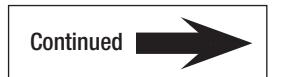
3. Install thermal pin as follows:
- METAL DOORS: First insert sleeve into door then insert pin. Use a wood block as spacer, gently tap pin into door until fl ush with edge.
- WOOD DOORS: First insert sleeve into pin, then insert into door. Use a wood block as spacer, gently tap combined pin and sleeve into door until fl ush with edge. Rubber Mallet
- 4. Install cap plug.
Horizontal Installation
Complete Installation
Corbin Russwin, Inc. U.S.A.
Product Support Tel 888.607.5703 • www.corbinrusswin.com
Assa Abloy Door Securities Canada
Product Support Tel 800.461.3007 • www.assaabloy.com
International
Assa Abloy Americas International
Product Support Tel 905.821.7775 • www.assaabloyai.com
Corbin Russwin, Inc., an ASSA ABLOY Group Brand.
Copyright ©2016 Corbin Russwin, Inc., an ASSA ABLOY Group Company. All rights reserved. Reproduction in whole or in part without the express written permission of Corbin Russwin, Inc. is prohibited. These materials are protected under U.S. copyright laws. All contents current at time of publication. Corbin Russwin, Inc. reserves the right to change availability of any item in this document, its design, construction, and/or its materials.
FM547B 12/16