Installation Instructions
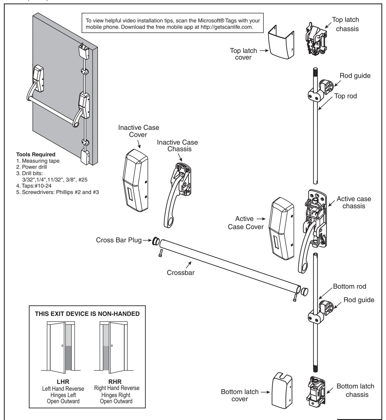
ED3400/ED3400A Series Surface Vertical Rod Exit Devices

In U.S.: Corbin Russwin, Inc. 225 Episcopal Road Berlin, CT 06037 USA www.corbinrusswin.com
In Canada: ASSA ABLOY Door Security Solutions Canada 160 Four Valley Drive Vaughan, Ontario, Canada L4K4T9 www.assaabloy.ca
Technical Product Support: Phone: 888-607-5703
FM361 (05/15)


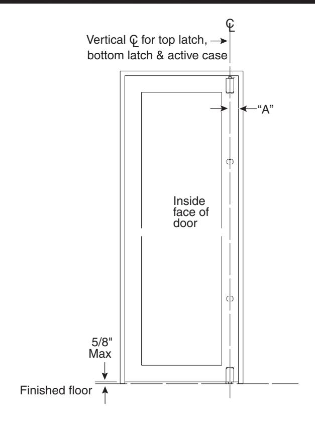
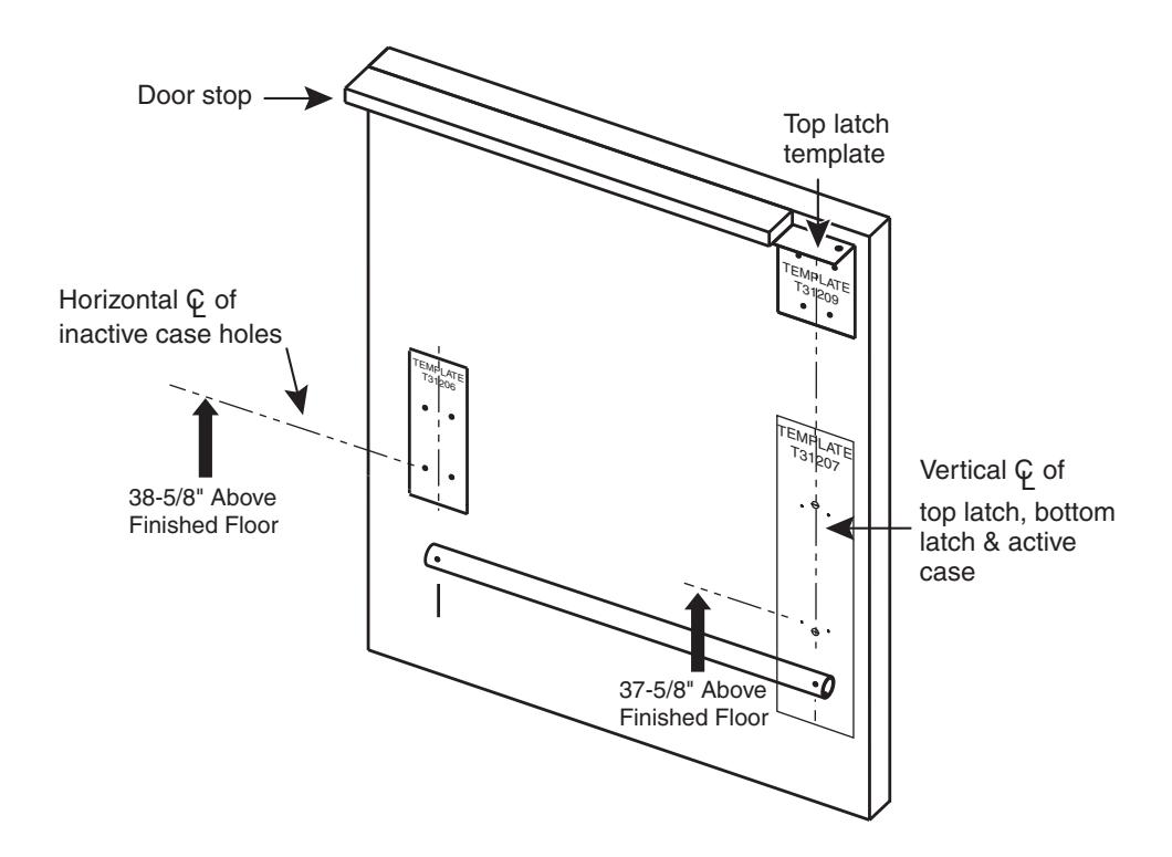
A. Template
-
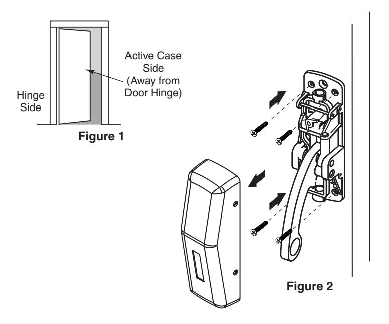
1. Mark the vertical centerline on inside of door as follows:
- If stile is 4-1/2" wide or greater, measure 2-3/4" from doorstop
- If stile is less than 4-1/2" wide, make "A" equal to 1/2 the width of the exposed lock stile (when door is closed against stop)
- 2. Measure 37-5/8" above finished floor and draw horizontal line for active case template.
- Align template (T31207) for active case with centerline and tape.
- 4. Using crossbar hole centers for measuring, draw vertical centerline of inactive case.
- Measure 38-5/8" above finished floor and draw horizontal line for inactive case template (1" higher than the active case).
- Align template (T31206) for inactive case with centerline and tape.
- 7. Position top strike template (T31209) into place.
- 8. Center punch mounting holes for active and inactive case, and top strike.
- 9. Drill and tap holes in door, per templates.


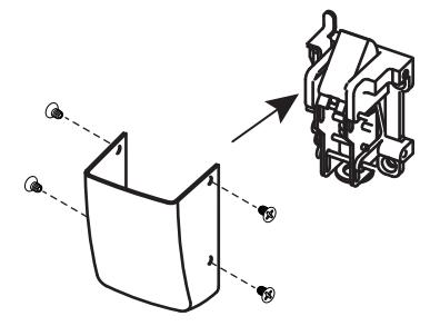
B. Active Case
- Remove cover from active case chassis.
- 2. Mount chassis to door as indicated in Figures 1 and 2.
- 3. If installing a cylinder function, ensure hub pin is in correct position (see Step B2.)
NOTE: Active Case is larger than Inactive Case.
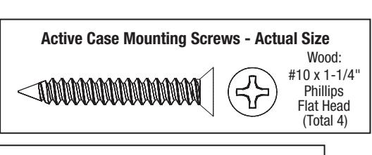
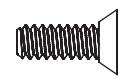
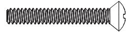
Active Case Mounting Screws - Actual Size Metal:
Ph U
Metal: #10-24 x 3/4" Phillips Flat Under Cut (Total 4)
B2.
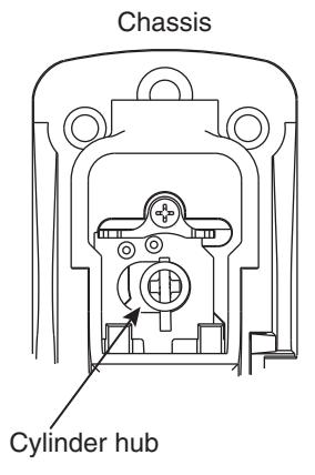
For ED3457A (Nightlatch) long end of pin faces down. Cylinder turns 180° in both directions.
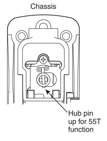
For ED3455A/ED3455AT (Classroom) long end of pin faces up. Cylinder turns 360° to the left or right.


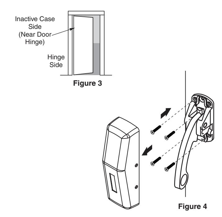
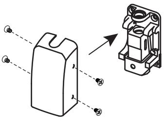
C. Inactive Case
- 1. Remove cover.
- 2. Mount chassis to door as indicated in Figures 3 and 4.
NOTE: Active Case is larger than Inactive Case.
Inactive Case Mounting Screws - Actual Size
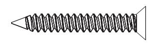

Wood: 10 x 1-1/4" Phillips Flat Head (Total 4)
Inactive Case Mounting Screws - Actual Size
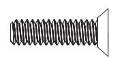

Metal: #10-24 x 3/4" Phillips Flat Under Cut (Total 4)

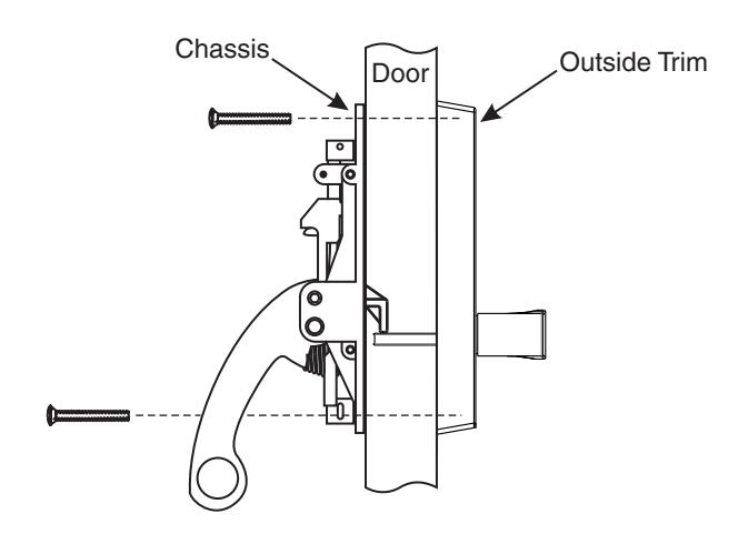
D. Outside Trim
- 1. Thread cylinder into outside trim (if applicable).
- 2. Slide thrubolt screws thru inside chassis and door.
- 3. Align outside trim with exposed thrubolt screws and secure.
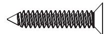
Outside Trim Mounting Screws - Actual Size
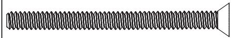

1/4 -20 x 2-3/8" Phillips Flat Head (Total 2)
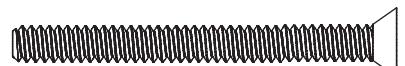
Cylinder Mounting Screws - Actual Size
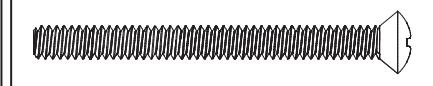

#10-24 x 2" Phillips Oval Head Machine Screw (Total 2)


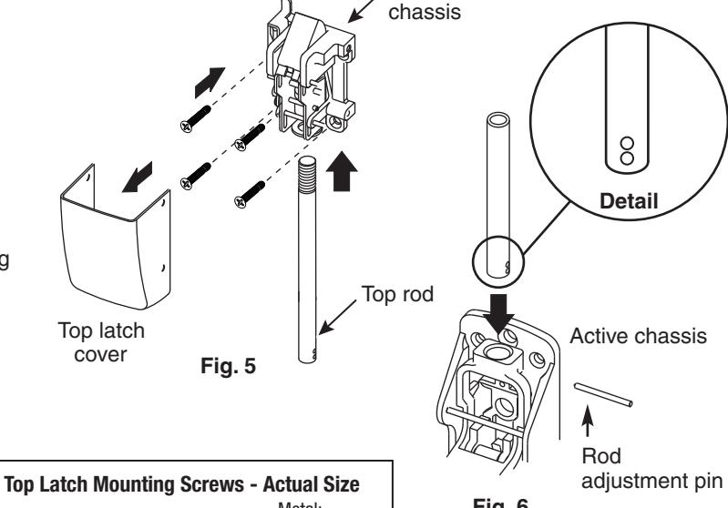
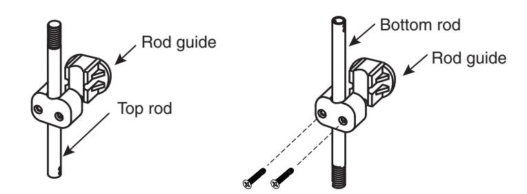
E. Top Latch & Rod
- 1. Remove cover.
- 2. Screw top rod into top latch chassis halfway (Fig. 5).
- 3. Confirm crossbar arm is NOT in dogged position.
- 4. Remove top rod pin from active chassis and slide top rod into active chassis (Fig. 6).
- Attach top latch chassis to door with screws according to template.
Note: Use through-bolt screws for fire rated doors.
- 6. Ensure top latch bolt is fully extended.
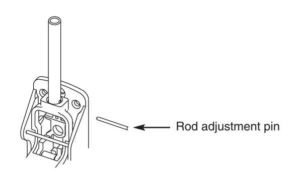
- 7. Rotate rod until upper hole (see detail) aligns with hole in active chassis and insert rod adjustment pin.
Top latch
Top Latch Mounting Screws - Actual Size
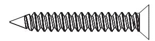

Wood: #10 x 1-1/4" Phillips Flat Head (Total 4)
Metal: #10-24 x 3/4" Phillips Flat Under Cut (Total 4)

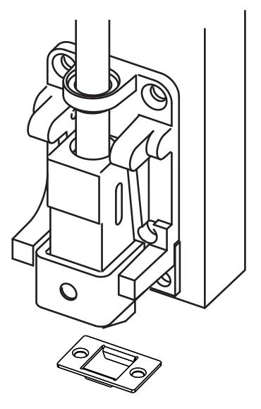
F. Mount Bottom Rod Assembly
- 1. Remove cover.
- Position bottom case on door, centered on vertical center line. Raise or lower to achieve gap indicated for strike application. (See drawings at right.)
- 3. Mark and center punch mounting holes for bottom latch.
- 4. Drill and tap mounting holes.
- 5. Screw bottom rod into bottom latch chassis until finger tight.
- 6. Confirm crossbar arm is NOT in dogged position.
- 7. Remove bottom rod pin from active chassis and slide bottom rod into active chassis.
- Attach bottom latch chassis to door.Note: Use through-bolt screws for fire rated doors.
- 9. Ensure bottom latch bolt is fully extended.
- 10. Rotate rod until middle hole aligns with hole in active chassis and insert rod adjustment pin.
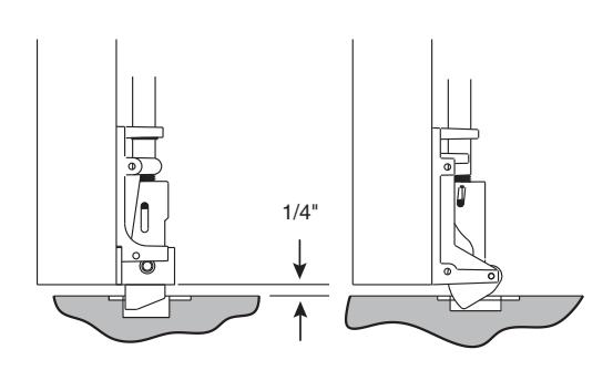
Mortise applied strikes
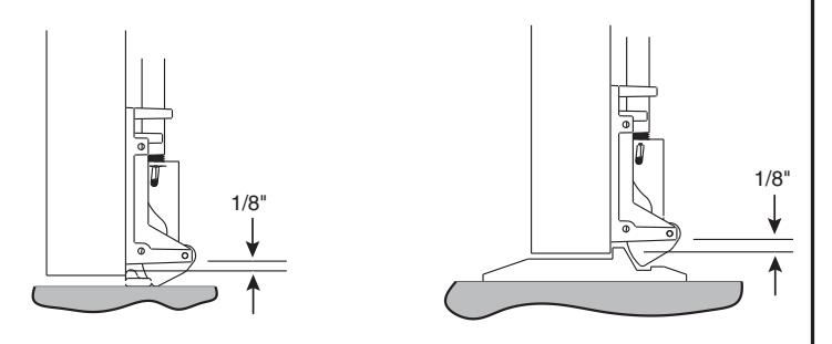
Surface applied strike
Latch track thresholds (by others)


G. Adjustment
- 1. Depress crossbar arm to verify top latch goes into holdback.
- If latch does not go into hold back, pull out the adjustment pin. Rotate top rod counterclockwise one complete turn, reinsert pin and test again. Continue this step until holdback is achieved.
Note: If there is minimal thread engagement with top latch chassis, use lower hole in rod to secure to active chassis.
Note: If rod is rotated too far into top latch, engagement with top strike will not occur or will be minimal. Rotate rod counterclockwise for additional engagement.

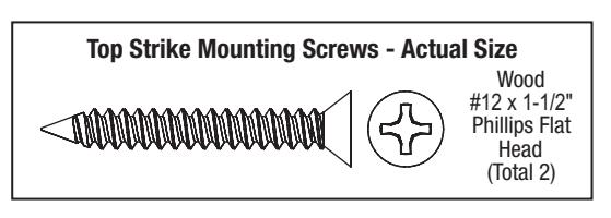
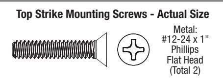
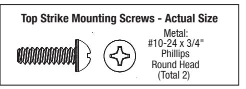
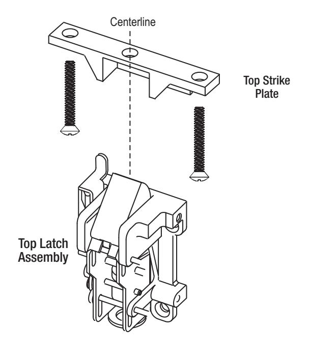
H. Top Strike
1. Align top strike with holes on doorstop of frame and secure.
Note: Thick end of strike gets aligned closest to door.
2. Close door and verify engagement of top strike and latch.


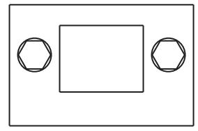
I. Mount Bottom Strike
Mark and install according to appropriate template and following notes.
For surface applied strikes:
- 1. Transfer vertical centerline to floor or threshold and mark.
- 2. Center strike on line marked.
- 3. Mark mounting holes. (If using Flush Bottom Strike (S03), mark mounting holes and outline of strike.)
- 4. Drill holes for screws.
- 5. Mount strike with screws provided.
- 6. Tighten screws.
Surface Projecting Bottom Strike Mounting Screws Actual Size Metal.

Metal: #12-24 x 1/2" Phillips Flat Head (Total 2)


Wood: #12 x 1" Phillips Flat Head (Total 2)
Flush Bottom Strike Mounting Screws - Actual Size

1/4 -20 x 2" Phillips Flat Head (Total 2)
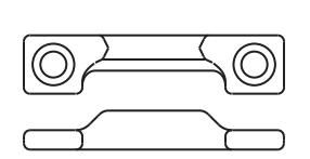
Surface Projecting Bottom Strike


J. Covers
1. Attach covers to both case chassis and latch chassis.

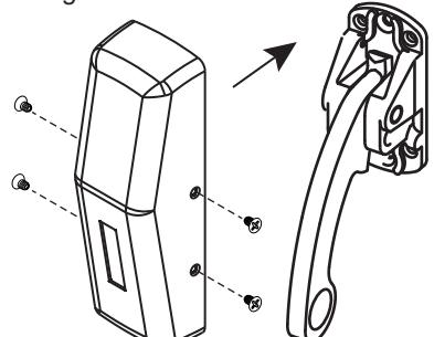
Inactive Case Chassis
Latch Chassis Screws - Actual Size

\
#8-32 x 5/16" Phillips Oval Head (Total 8)
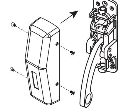
Active Case Chassis
Case Chassis Screws - Actual Size


#8-32 x 7/32" Phillips Oval Head (Total 8)
Top Latch Chassis
Bottom Latch Chassis


K. Rod Guides
- Insert top and bottom rod guides at center of each rod and secure.
- Test to confirm rods move smoothly in rod guide and do not bind. If not, loosen screws slightly.


#10-24 x 1-1/4" Phillips Oval Head (Total 4)
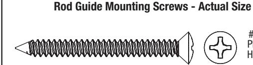
Wood: #8 x 1-3/4" Phillips Oval Head Screw (Total 4)

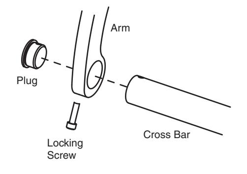
L. Crossbar
- 1. Slide crossbar into active chassis arm.
- 2. Slide crossbar into inactive chassis arm.
- 3. Insert plugs and secure to bar with locking screws.
- 4. Depress the crossbar to confirm the latchbolts retract and the top latch goes into latch holdback.
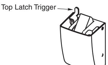
- 5. Test top latch trigger to confirm rods drop when door closes.
Crossbar Mounting Screws - Actual Size

#10-24 x 3/4" Socket Head Cap Screw (Total 2)
M. Top Latch Trigger
1. Press down on top latch trigger to confirm latchbolt and rods retract.