Installation Instructions

ML2000 Series Mortise Locks with Sectional/Rose Trim
Motorized Electric Latch Retraction (MELR)

The accuracy of the door preparation is critical for proper functioning and security of this lock. Misalignment can cause premature wear and a lessening of security.
Tools Required:
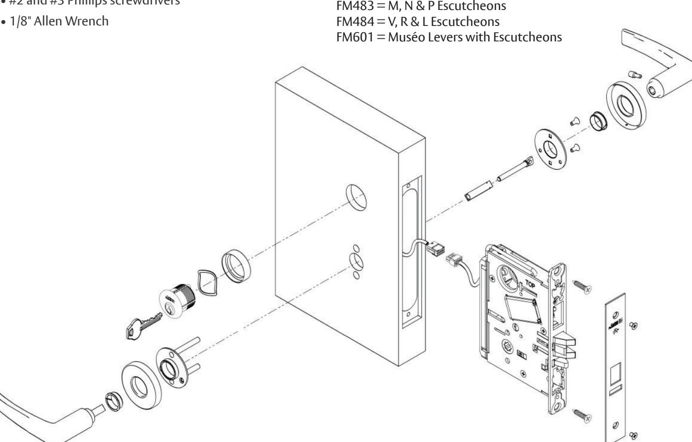
• #2 and #3 Phillips screwdrivers
For escutcheon trim installation, please refer to the following instruction documents:
WARNING
This product can expose you to lead which is known to the state of California to cause cancer and birth defects or other reproductive harm. For more information go to www. P65warnings.ca.gov.
WARNING
Changes or modifi cations to this unit, not expressly approved by the party responsible for compliance could void the user's authority to operate the equipment.
WARNING
Attention Installer: Improper installation may result in damage to the product and void the factory warranty.
For installation assistance contact Corbin Russwin 1-800-810-WIRE (9473) • techsupport.corbinrusswin@assaabloy.com
Motorized Electric Latch Retraction (MELR)
Installation Instructions


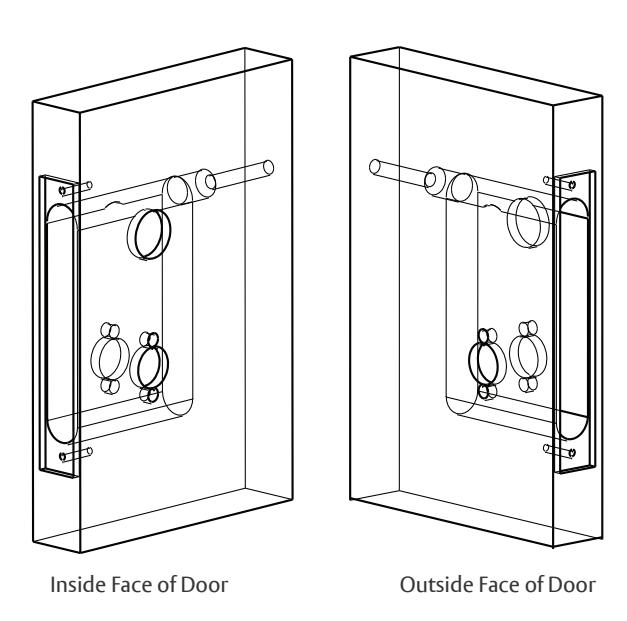
1 Door Preparation
Prep door according to supplied door marker. For door manufacturer templates, visit www.corbinrusswin.com.
2 Handing
Verify hand and bevel of door. Illustrations shown are as viewed from the outside or secure side of opening.
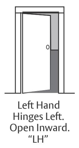
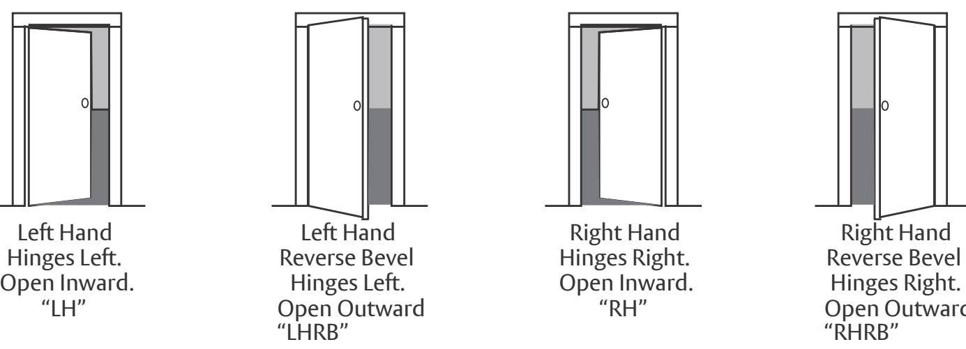
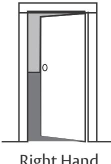
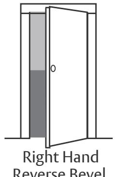
"RH" Open Outward "RHRB"
For installation assistance contact Corbin Russwin 1-800-810-WIRE (9473) • techsupport.corbinrusswin@assaabloy.com
Copyright © 2024, ASSA ABLOY Access and Egress Hardware Group, Inc. All rights reserved. Reproduction in whole or in part without the express written permission of ASSA ABLOY Access and Egress Hardware Group, Inc. is prohibited.
Motorized Electric Latch Retraction (MELR)
Installation Instructions
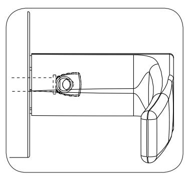
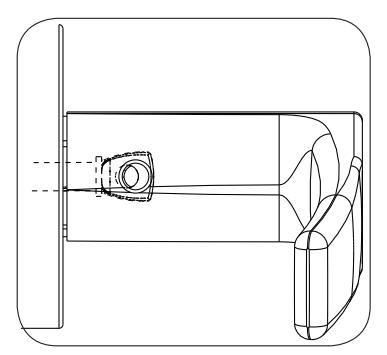
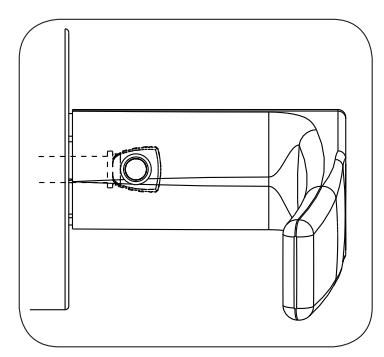
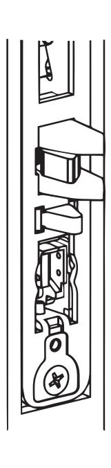
3 Latch Handing Instructions
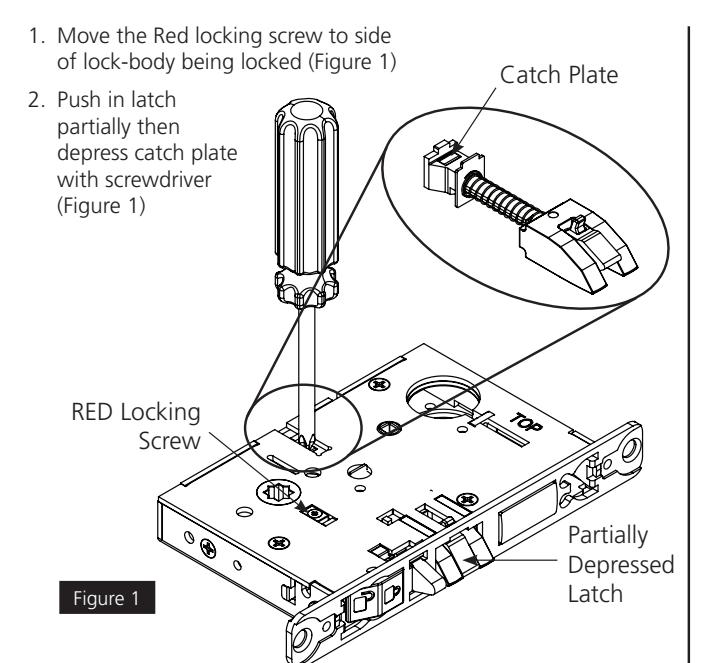
3. Pull latch out of lock-body and rotate 180 degrees (Figure 2)
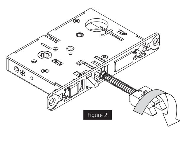
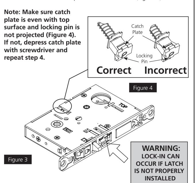
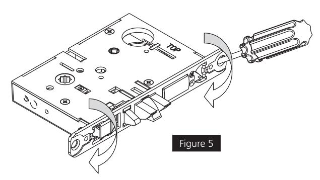
4. Push in latch until tail-piece hits back of case (Figure 3) 5. Rotate lock front to match bevel of door as shown (Figure 5)
Motorized Electric Latch Retraction (MELR)
Installation Instructions

5 Install Lock Body into Door
1. Plug mortise lock harness into ElectroLynx® harness in door (Figure 6).

2. Install, but do not tighten two #12 x 1" combination screws through lock body (Figure 6).
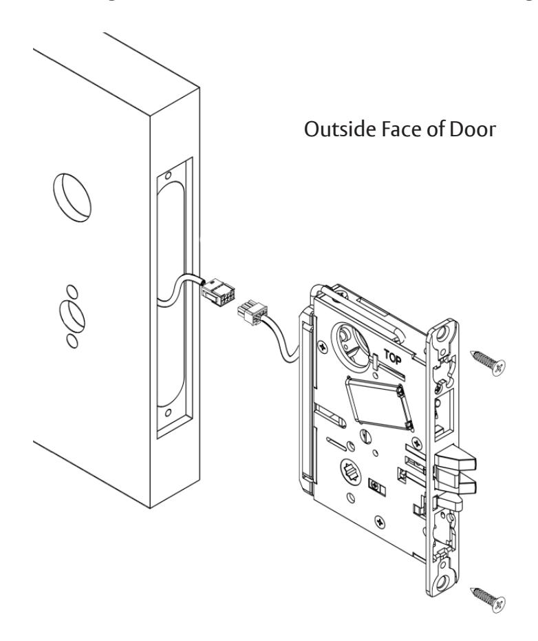
(2) #12 x 1" Do not tighten.
Figure 6
Motorized Electric Latch Retraction (MELR)
Installation Instructions

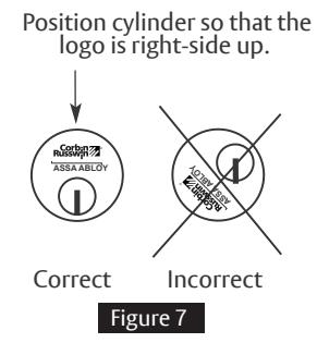
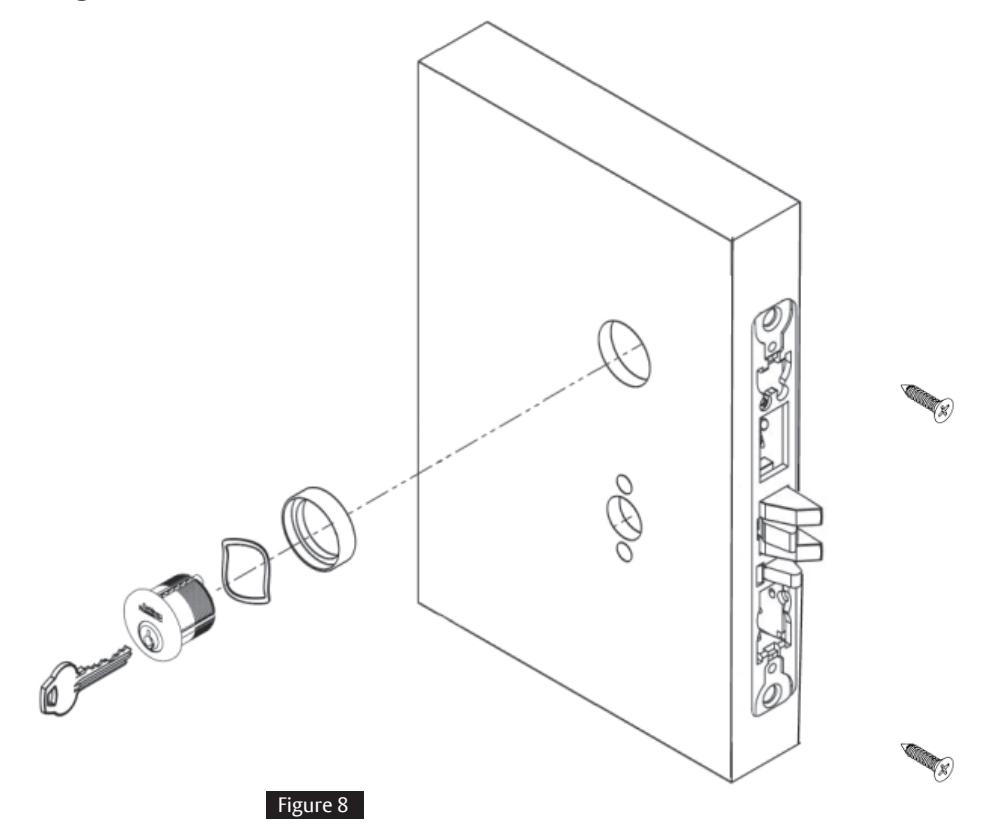
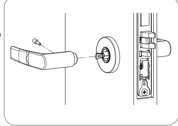
6 Install cylinder with wave spring and collar, if required

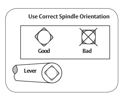
NOTE: Cylinder must be oriented correctly (Figure 7). Pull key slightly out of cylinder to help thread into lockbody.
- 1. Secure with cylinder set screw (Figure 8).
- 2. Tighten lock mounting screws.
Motorized Electric Latch Retraction (MELR)
Installation Instructions

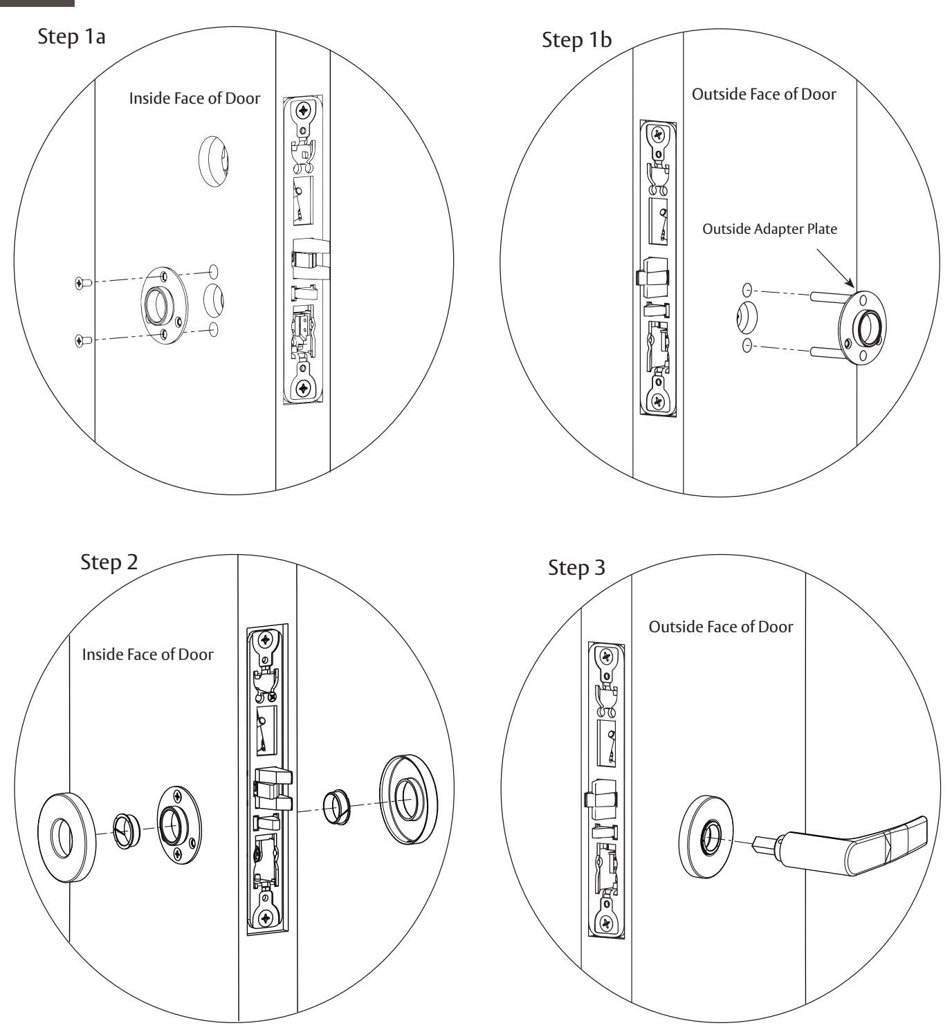
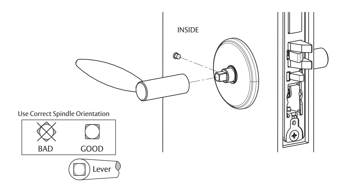
7 Install Standard Lever Trim (See Section 8 for Museo Trim.)
For installation assistance contact Corbin Russwin 1-800-810-WIRE (9473) • techsupport.corbinrusswin@assaabloy.com
FM804 05/24
Motorized Electric Latch Retraction (MELR)
Installation Instructions

7 Install Standard Lever Trim, continued
Step 4
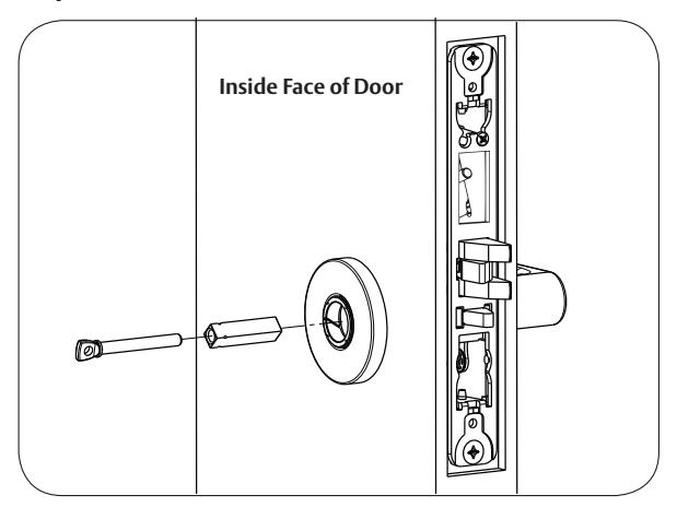
Step 5 Align adjustment bolt with threaded hole in lever

Adjustment bolt needs to be unthreaded.
Adjustment bolt fully aligned.
Step 6
Notes:
- Unthread Adjustment Bolt approximately four turns for a good starting point (After being fully tightened)
- Make sure O/S lever is fully inserted into adapter plate before aligning adjustment bolt.
Motorized Electric Latch Retraction (MELR)
Installation Instructions

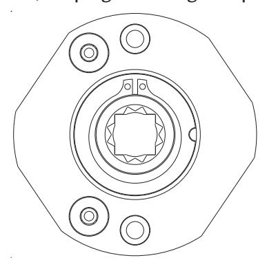
8 Install Museo Trim
1.)
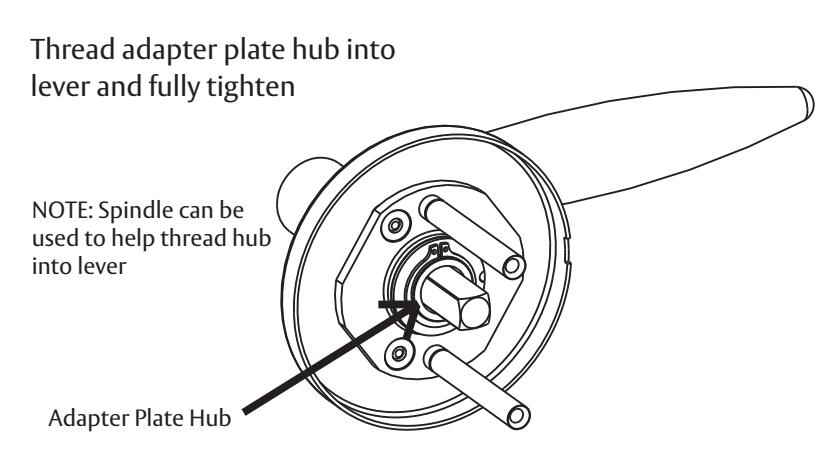
Align adapter plate hub with square hole in lever; keeping hub as tight as possible
2.)
1-800-810-WIRE (9473) • techsupport.corbinrusswin@assaabloy.com
Copyright © 2024, ASSA ABLOY Access and Egress Hardware Group, Inc. All rights reserved. Reproduction in whole or in part without the express written permission of ASSA ABLOY Access
8
FM804 05/24
and Egress Hardware Group, Inc. is prohibited.
Motorized Electric Latch Retraction (MELR)
Installation Instructions

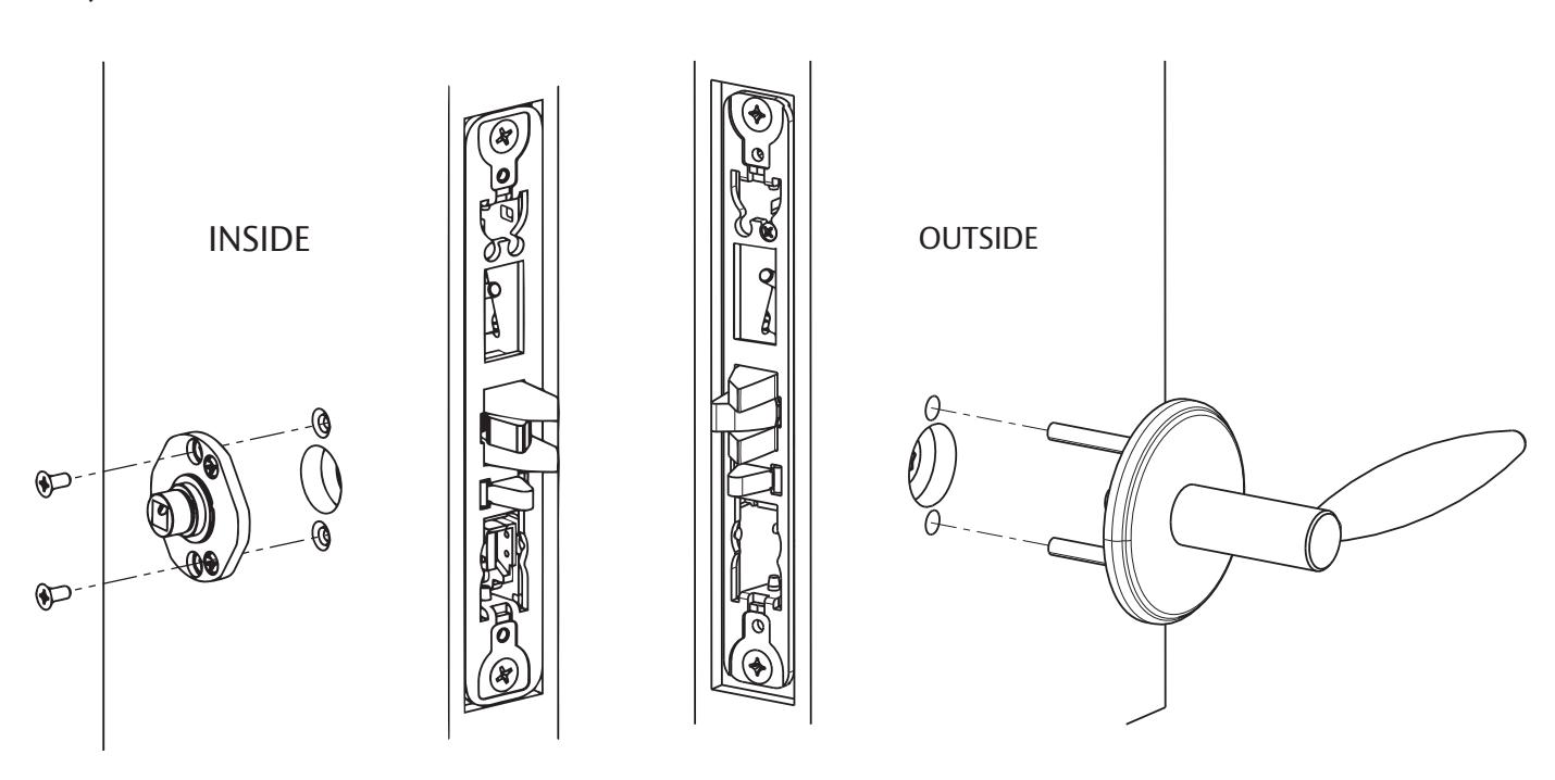
8 Install Museo Trim, continued
3.) Set screw in hub faces away from door edge.
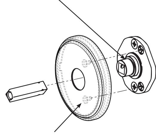
Align studs on rose with bushings in adapter plate
4.)
Motorized Electric Latch Retraction (MELR)
Installation Instructions

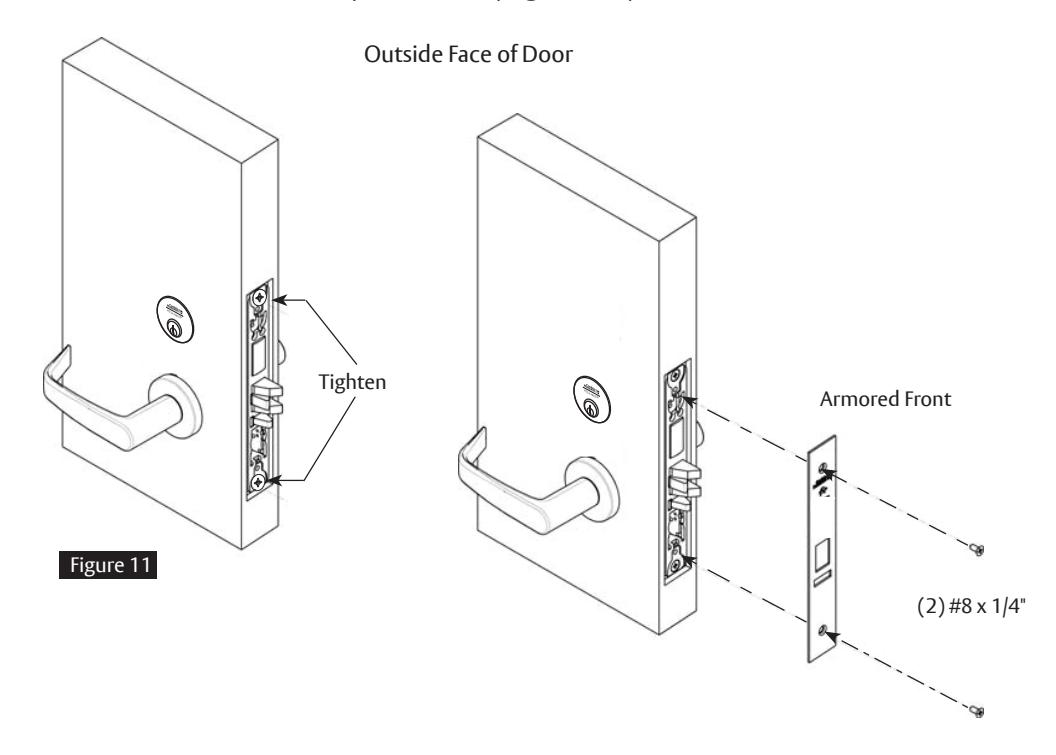
9 Install Armored Front
- 1. Tighten (2) screws through lock body.
- 2. Attach armored front with two #8 x 1/4" screws (Figure 11).
10 Mechanical Operational Check
For mortise locks with cylinders:
- 1. Insert key into cylinder and rotate: There should be no friction against lock case, wire harness or any other obstructions.
- 2. The key will retract the latch: Key should rotate freely.
- 3. Inside lever: Ensure it retracts the latch.
- 4. Close door: Ensure latch fully extends and does not bind.
Motorized Electric Latch Retraction (MELR)
Installation Instructions

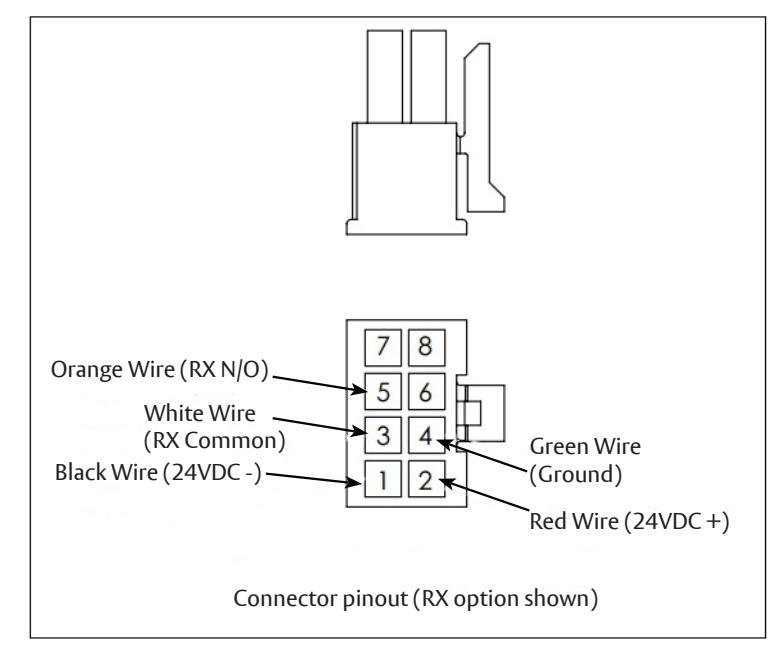
11 Wiring Diagram - Lock Schematic

Check polarity. Verify + (red) wire. For assistance, call 800-810-WIRE.
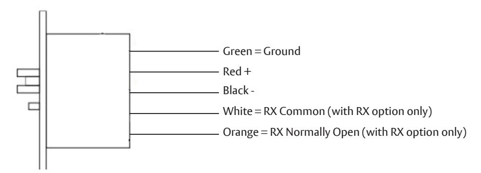
Electrical Specifi cations
• Voltage: 24 VDC
• Operating Current: 700mA
• Hold Current: 50mA
• RX Switch: 24 VDC Max, 1 kΩ resistive
minimum, 24mA Max
Notes:
- The minimum permissible wire size to be used shall not be less than 26 AWG.
- Shall be powered by a UL294 and ULC-60839 Class 2 Power Limited power supply or Listed Control units.
- Wiring methods shall be in accordance with the National Electrical Code (ANSI/ NFPA70), CSA 22.1, Canadian Electrical Code (CEC), Part I, Safety Standard for Electrical Installations, local codes and the authorities having jurisdiction.
- The system shall not be installed unless permitted by the local authority having jurisdiction and shall not interfere with the operation of listed panic hardware.
- ULC-60839-11-1 Grade 1 and Environmental class: Indoor Use.
- Endurance Level IV, Line Security Level I, Attack Level I, Power Standby Level I.
Motorized Electric Latch Retraction (MELR)
Installation Instructions
12 Wiring Diagram - Simple Latch Retraction
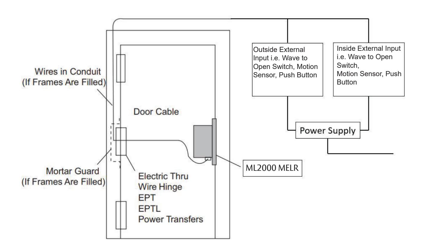
Operation: Activating inside or outside external input will retract latchbolt. Latchbolt remains retracted until power off.
Motorized Electric Latch Retraction (MELR)
Installation Instructions
13 Wiring Diagram - Automatic Door
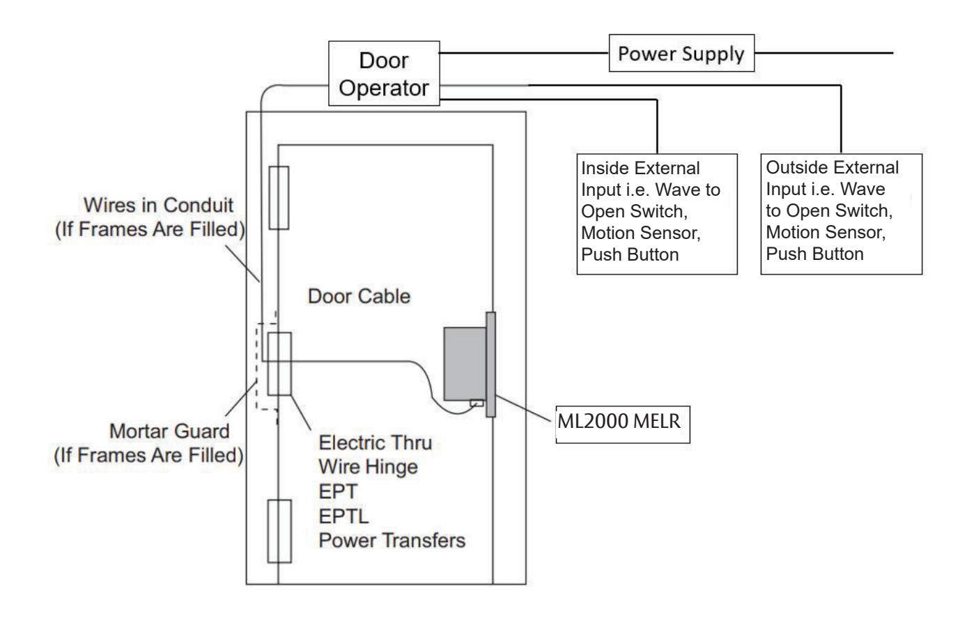
Operation: Activating inside or outside external input will retract latchbolt and door operator will open the door. Latchbolt remains retracted until power off.
Motorized Electric Latch Retraction (MELR)
Installation Instructions

14 Wiring Diagram - Restroom Privacy
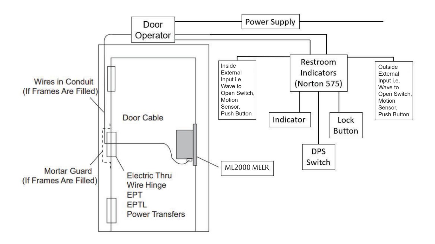
Operation: Activating inside or outside external input will retract latchbolt and door operator will open the door, unless outside external input is disabled by lock button. Indicator will illuminate when outside external input is disabled. Latchbolt remains retracted until power off.
Consult factory for electrical system layouts, riser and wiring diagrams.
Motorized Electric Latch Retraction (MELR)
Installation Instructions


15 Electrical Operational Check
Latch retraction check:
- 1. Turn power ON.
- 2. Send latch retraction signal from control panel.
- 3. Verify latch retracts and re-projects at desired intervals.