


Installation Instructions
ED3200/ED3200A Series Rim Exit Device
ASSA ARI OY
In U.S.: Corbin Russwin, Inc. 225 Episcopal Road Berlin, CT 06037 USA www.corbinrusswin.com
In Canada: ASSA ABLOY Door Security Solutions Canada 160 Four Valley Drive Vaughan, Ontario, Canada L4K4T9 www.assaabloy.ca
Technical Product Support: Phone: 888-607-5703
To view helpful video installation tips, scan the Microsoft® Tags with your mobile phone. Download the free mobile app at http://getscanlife.com.
FM362 (05/15)
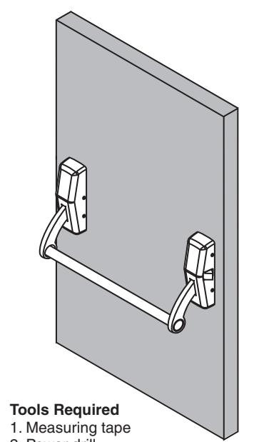
- 2. Power drill
- 3. Drill bits: 3/32",1/4",11/32", 3/8", #25
- 4. Taps:#10-24
- 5. Screwdrivers: Phillips #2 and #3

ASSA ABLOY
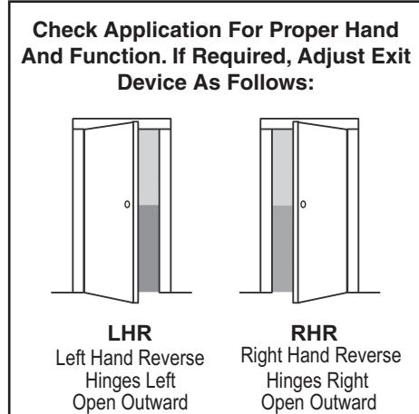
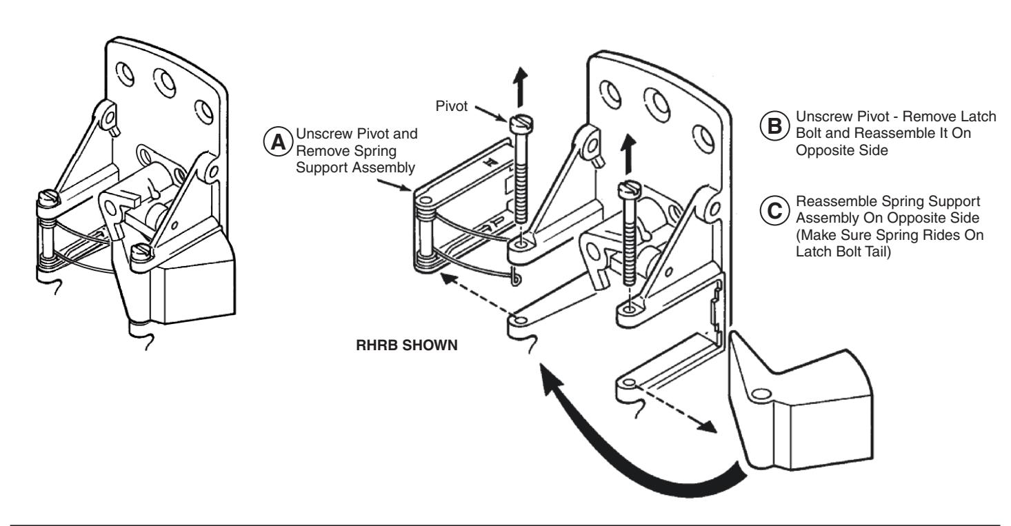
To Change Hand
Identify Type of Installation
ldentify type of installation to determine location of vertical હ
Single Door (Non-Fire Rated)
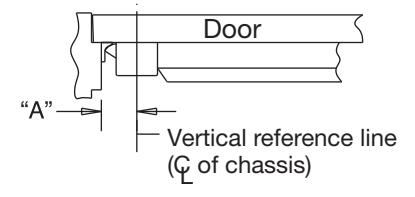
For Standard strike Dim. "A" = 2-1/4"
For S04 strike Dim. "A" = 1-3/4"
Double Door with 900 Mullion
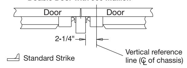
Double Doors With No Mullion
Vertical Centerline of Active Case DOOR 2-1/4" Use Strike S02

ASSA ABLOY

A. Template
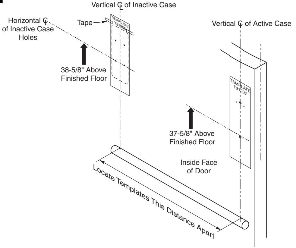
- Draw vertical centerline of active case based on types of installation.
- 2. Measure 37-5/8" above finished floor and draw horizontal line for active case template.
- 3. Align template (T31207) for active case with centerline and tape.
- 4. Using crossbar hole centers for measuring, draw vertical centerline of inactive case.
- Measure 38-5/8" above finished floor and draw horizontal line for inactive case template (1" higher than the active case).
- Align template (T31206) for inactive case with centerline and tape.
- 7. Pin punch mounting holes for active and inactive cases on door.
- 8. Drill and tap holes in door, per the template (T31207).


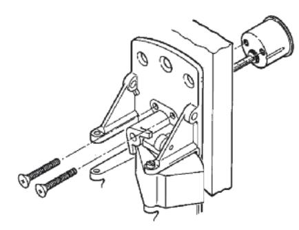
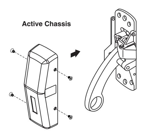
B. Active Case
- Press in latchbolt and remove cover from active case chassis.
- Mount chassis to door as indicated in Figures 1 and 2.
- Depress the chassis arm to confirm the latchbolt retracts.
Active Case Mounting Screws - Actual Size Wood: #10 x 1-1/
3 #1
#10 x 1-1/4" Phillips Flat Head (Total 4)


Metal: #10-24 x 3/4" Phillips Flat Under Cut (Total 4)
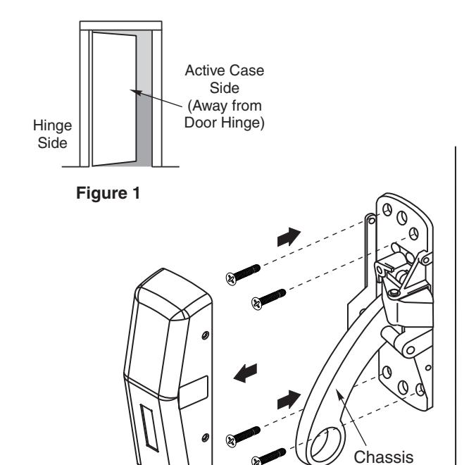
Figure 2
Arm

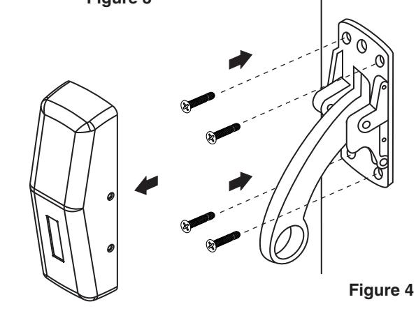
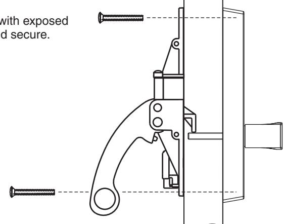
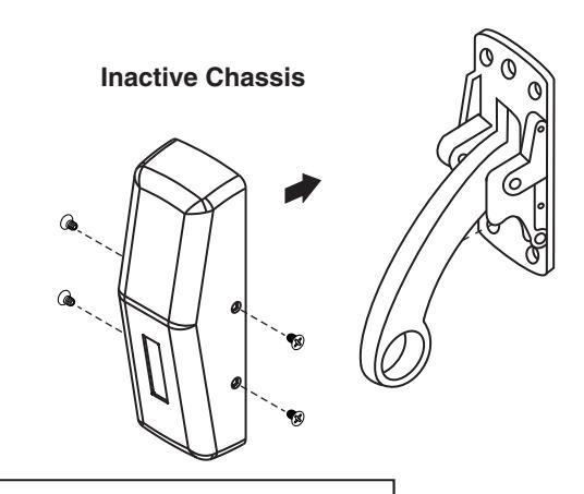
C. Inactive Case
- 1. Remove cover.
- 2. Mount chassis to door as indicated in Figures 3 and 4.
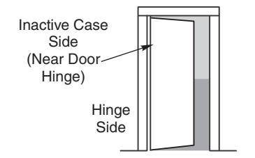
Figure 3
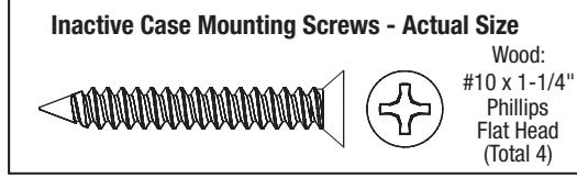
Inactive Case Mounting Screws - Actual Size

Metal: #10-24 x 3/4" Phillips Flat Under Cut (Total 4)


D. Attach Outside Trim
- 1. Slide thrubolt screws thru inside chassis.
- 2. Thread cylinder into outside trim (if applicable).

NOTE
For Nightlatch function, secure cylinder to chassis. This method allows cylinder to be removed at a later date for rekeying without taking device off door.
Outside Trim Mounting Screws - Actual Size
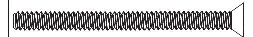

1/4 -20 x 2-3/8" Phillips Flat Head (Total 2)
Cylinder Mounting Screws - Actual Size

#10-24 x 2" Phillips Oval Head Machine Screw (Total 2)

E. Covers
1. Attach covers to both chassis and secure.
Cover Mounting Screws - Actual Size


#8-32 x 7/32" Phillips Oval Head (Total 8)


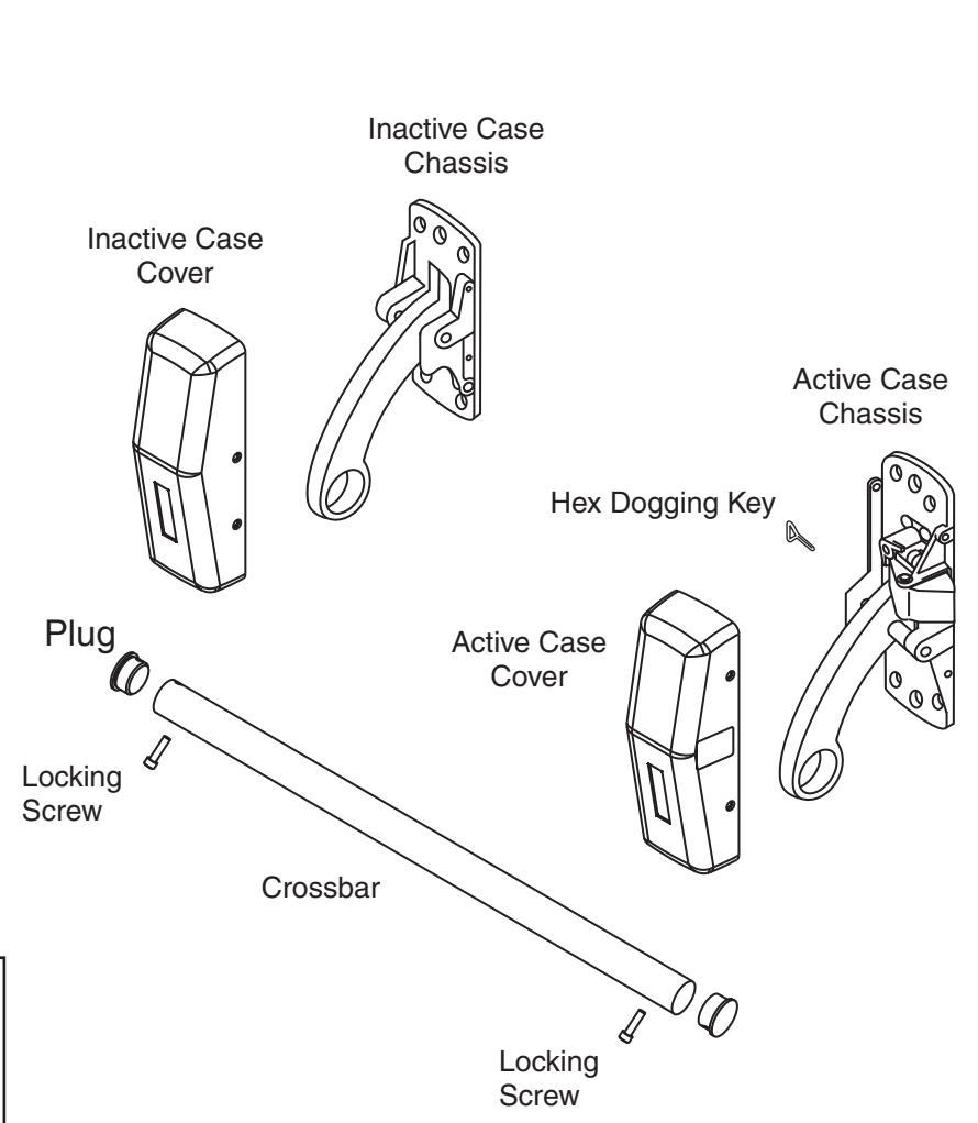
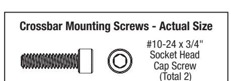
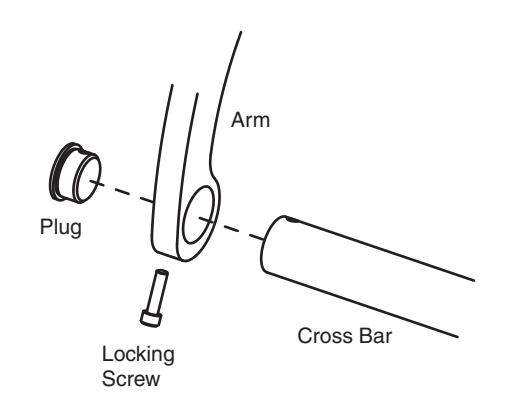
F. Crossbar
- 1. Slide crossbar into active chassis arm.
- 2. Slide crossbar into inactive chassis arm.
- Insert plugs and secure to bar with locking screws.
- 4. Depress the crossbar to confirm proper operation.
- 5. Test for full latch retraction when dogged.
G. Strike
- Align strike onto door frame and adjust for proper position.
- 2. Center punch mounting holes.
- 3. Drill and tap holes in frame.
- 4. Secure strike in place.
- 5. Standing inside the room, close door and confirm latchbolt fully engages.
Note: If latchbolt does not fully engage, review installation measurements of active and inactive chassis, and strike.