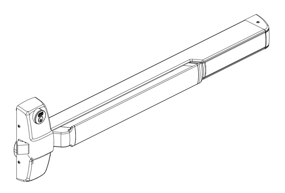
Installation Instructions

PED5200 & PED5200 A Series
Rim Exit Device for 10T, 55T, 42, & 42T Functions

This product can expose you to lead which is known to the state of California to cause cancer and birth defects or other reproductive harm. For more information go to www. P65warnings.ca.gov.
and Egress Hardware Group, Inc. is prohibited.
For installation assistance contact Corbin Russwin
1-800-543-3658 • techsupport.corbinrusswin@assaabloy.com Copyright © 2022, ASSA ABLOY Access and Egress Hardware Group, Inc. All rights reserved.
Reproduction in whole or in part without the express written permission of ASSA ABLOY Access
WARNING
Attention Installer: Improper installation may result in damage to the product and void the factory warranty.
Rim Exit Device for 10T, 55T, 42, & 42T Functions
Installation Instructions
Screw Chart
| SCREW |
TOTAL QTY
SUPPLIED |
WHERE USED |
|---|---|---|
|
#10-24 X 3/4" FLAT HEAD
MACHINE SCREW |
4 |
(4) CHASSIS
CORNER MOUNTING HOLES (METAL DOOR) |
|
#10 X 1-1/4" FLAT HEAD
WOOD SCREW |
4 |
(4) CHASSIS
CORNER MOUNTING HOLES (WOOD DOOR) |
|
#10-24 X 3/4" ROUND HEAD
MACHINE SCREW |
4 |
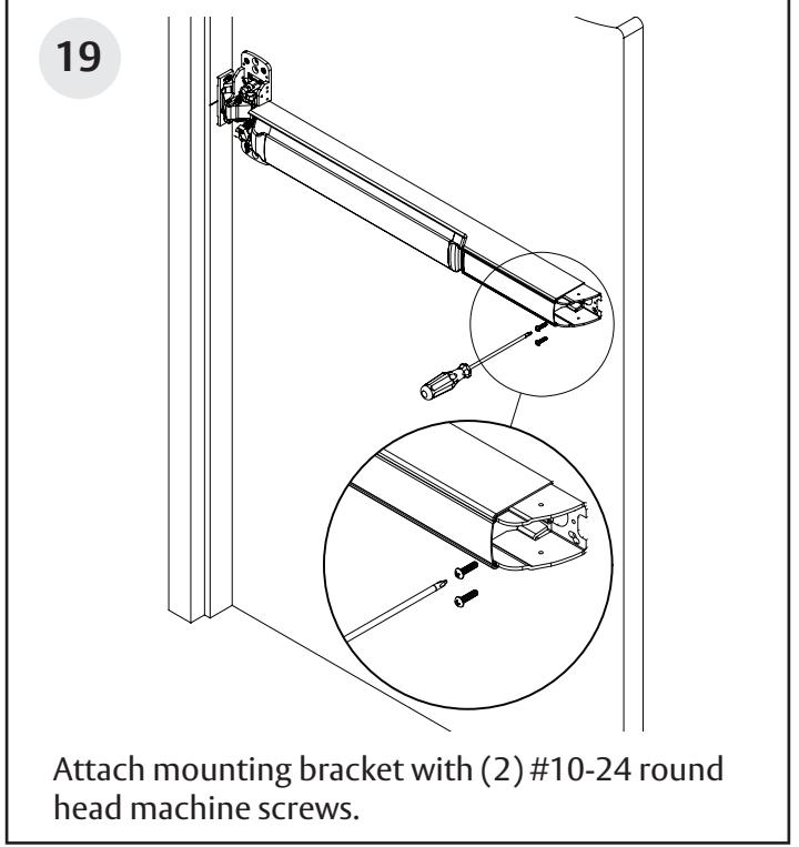
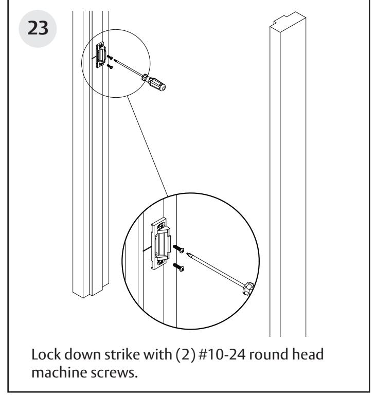
(2) REAR MOUNTING PLATE
(METAL DOOR) (2) 649 STRIKE INNER MOUNTING HOLES |
|
#10 X 1-1/4" ROUND HEAD
WOOD SCREW |
2 |
(2) REAR MOUNTING PLATE
(WOOD DOOR) |
|
#10-24 X 3/4" OVAL HEAD
MACHINE SCREW |
2 |
(2) 649 STRIKE
OUTER MOUNTING HOLES (METAL FRAME) |
|
#10 X 1-1/4" OVAL HEAD
WOOD SCREW |
2 |
(2) 649 STRIKE
OUTER MOUNTING HOLES (WOOD FRAME) |
|
#8-32 X 7/16" FLAT HEAD
MACHINE SCREW |
2 |
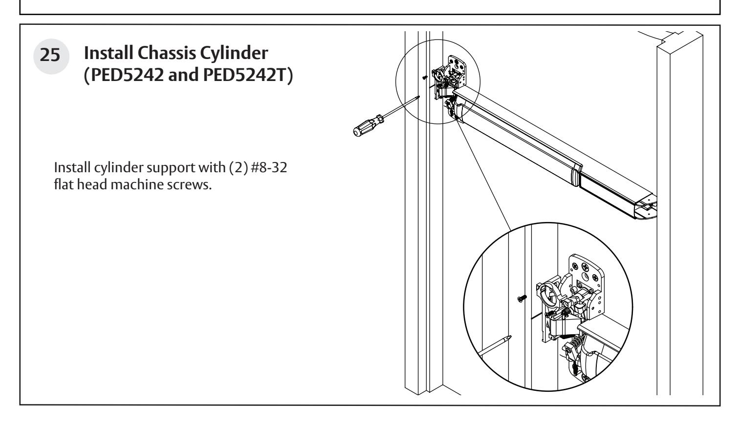
(2) CYLINDER SUPPORT
TO CHASSIS (42 & 42T FUNCTIONS ONLY) |
|
#8-32 X 1/4" SOCKET HEAD
SET SCREW |
1 |
(1) CYLINDER SUPPORT
TO CYLINDER (42 & 42T FUNCTIONS ONLY) |
|
#8-32 X 5/16" W/ #6 OVAL HEAD
MACHINE SCREW |
4 |
(2) CHASSIS COVER
FRAME SIDE (2) END CAP |
|
#8-32 X 5/8" W/ #6 OVAL HEAD
MACHINE SCREW |
2 |
(2) CHASSIS COVER
RAIL SIDE |
|
1/4"-20 X 2-3/8" KNURLED FLAT HEAD
MACHINE SCREW |
2 |
(2) EXIT TRIM
(IF USED) |
Rim Exit Device for 10T, 55T, 42, & 42T Functions
Installation Instructions
Tools Needed


Before installation:
- 1. Install mullion, if used.
- 2. Fit and hang door.
- 3. Check the box's label for the size of the exit device.
- 4. For wood doors, use wood screws and prep accordingly.
The surface of the door where the exit device is to be applied must be flush. Clear away any raised projections to allow exit device to rest on the flat surface of the door. If shim kit is required, contact your distributor.
Note: Please refer to trim and other installation instructions provided in the box.
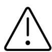
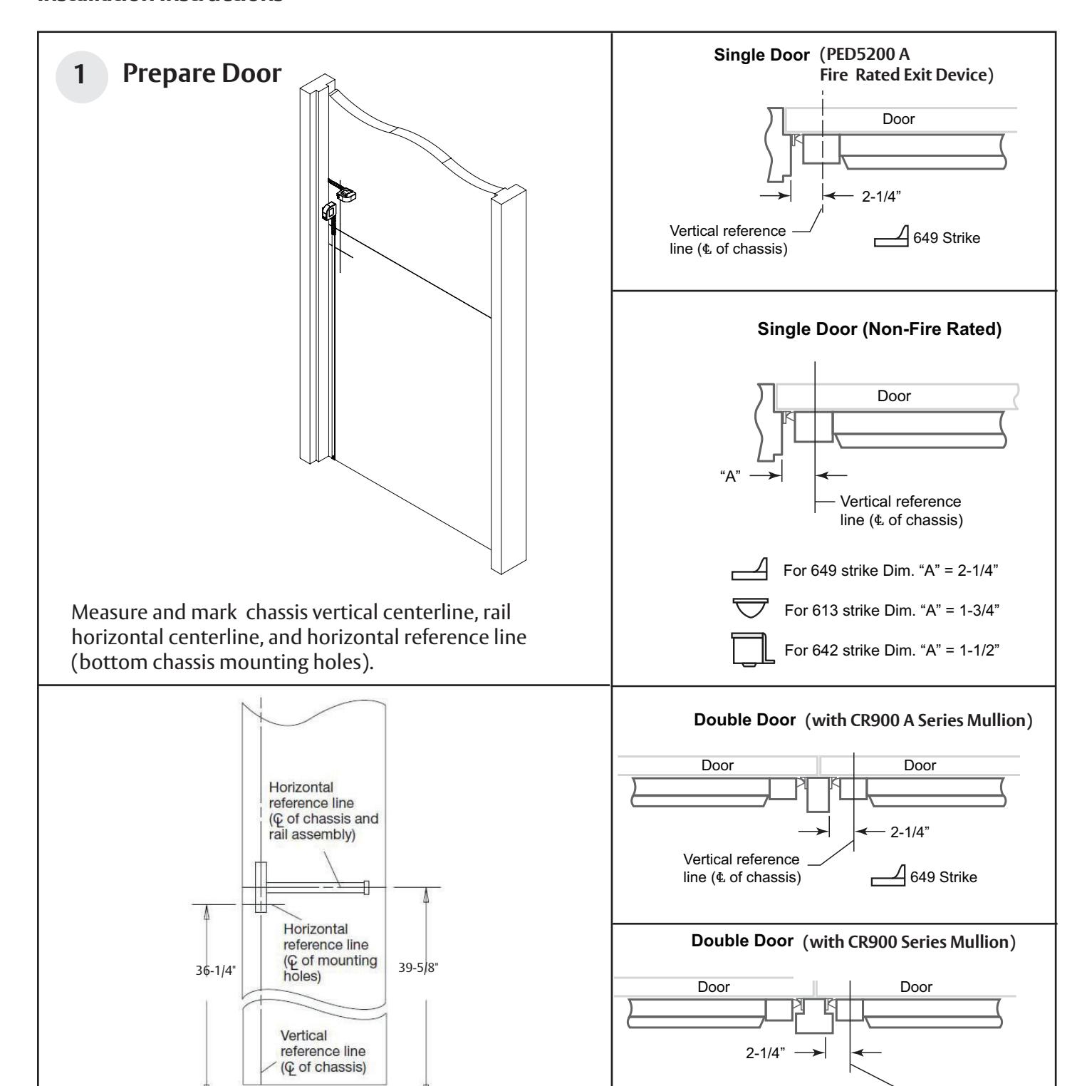
DOOR HANDS DETERMINED FROM OUTSIDE OF DOOR OR SECURED SIDE
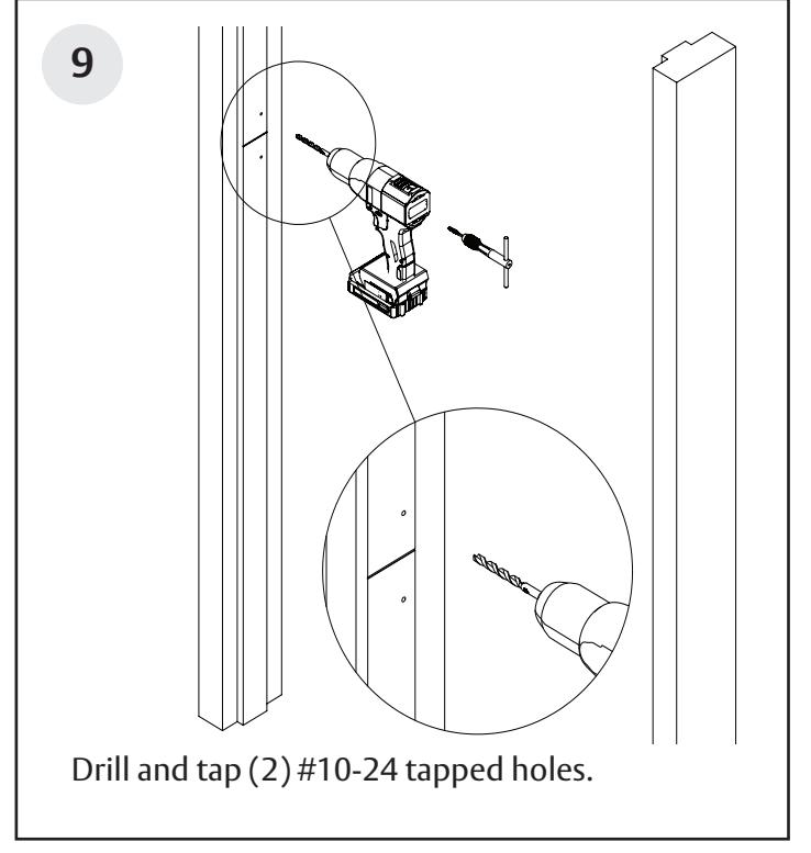
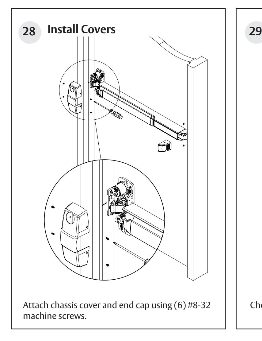
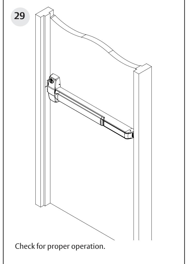
Rim Exit Device for 10T, 55T, 42, & 42T Functions
Installation Instructions
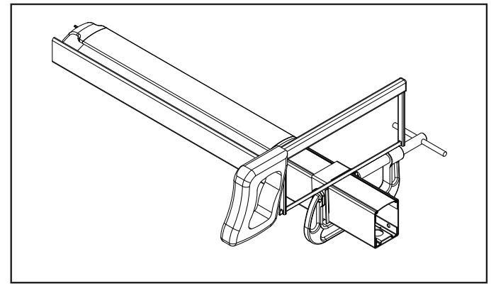
Exploded View
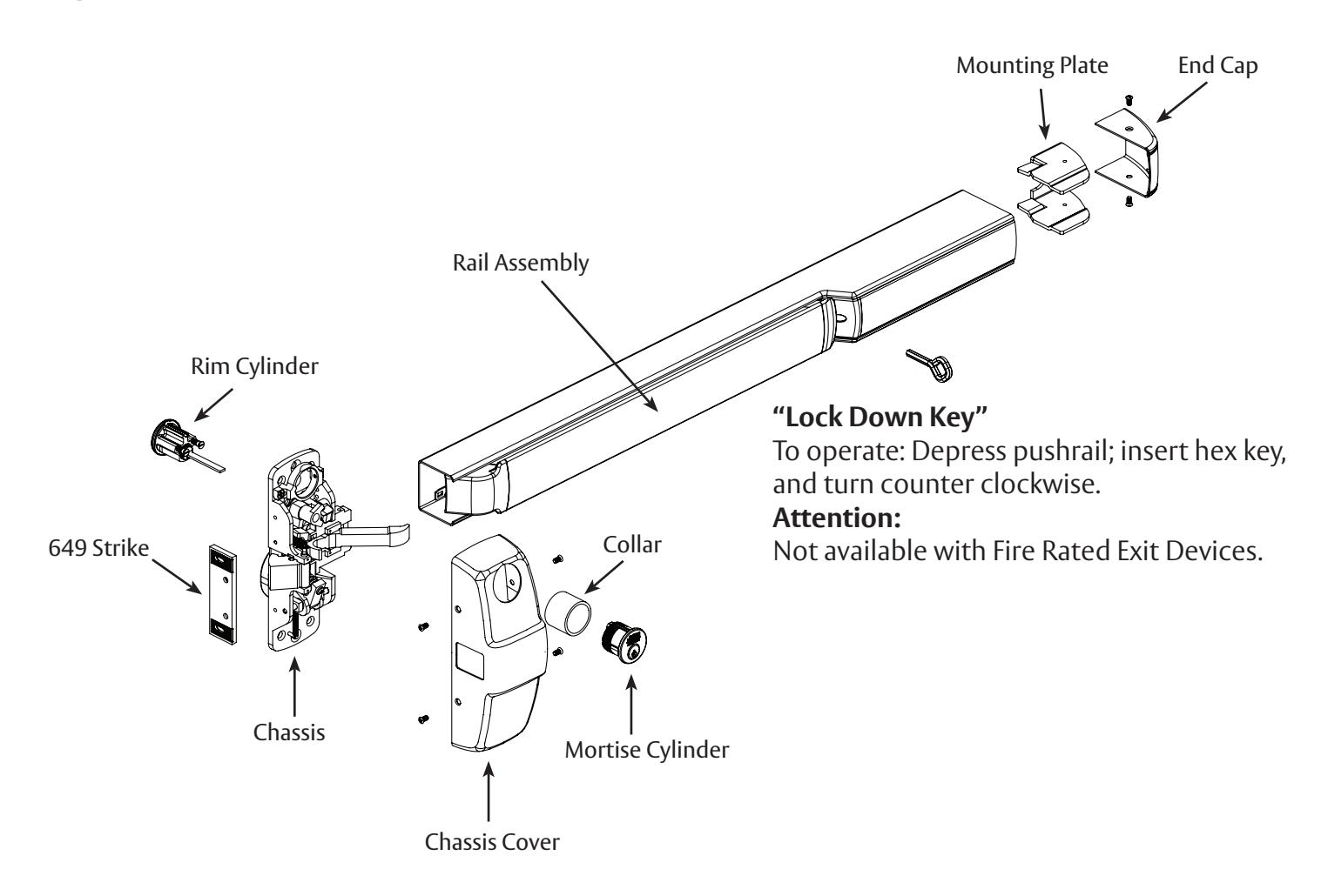
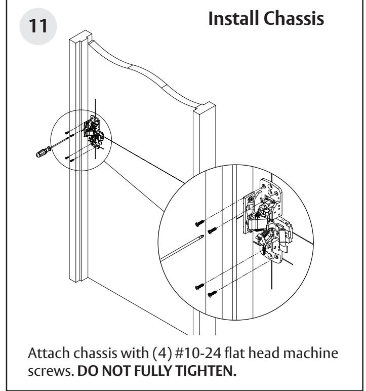
Rim Exit Device for 10T, 55T, 42, & 42T Functions
Installation Instructions
FM576 9/22
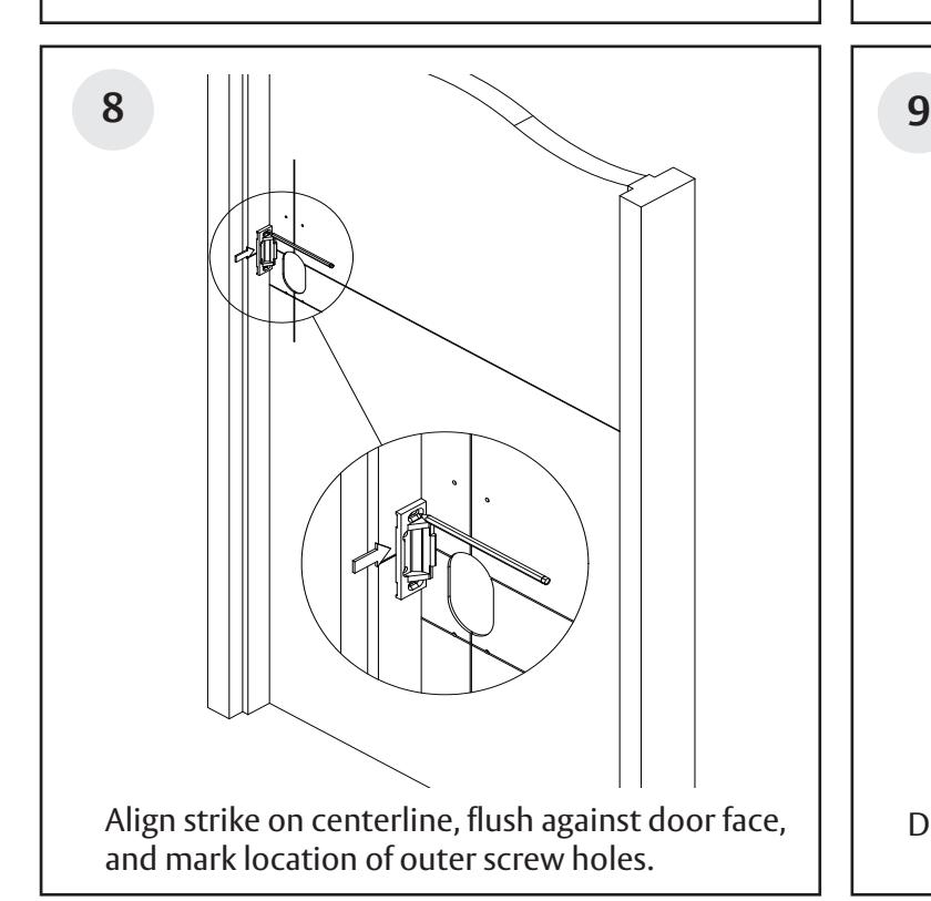
Vertical reference line (℄ of chassis)
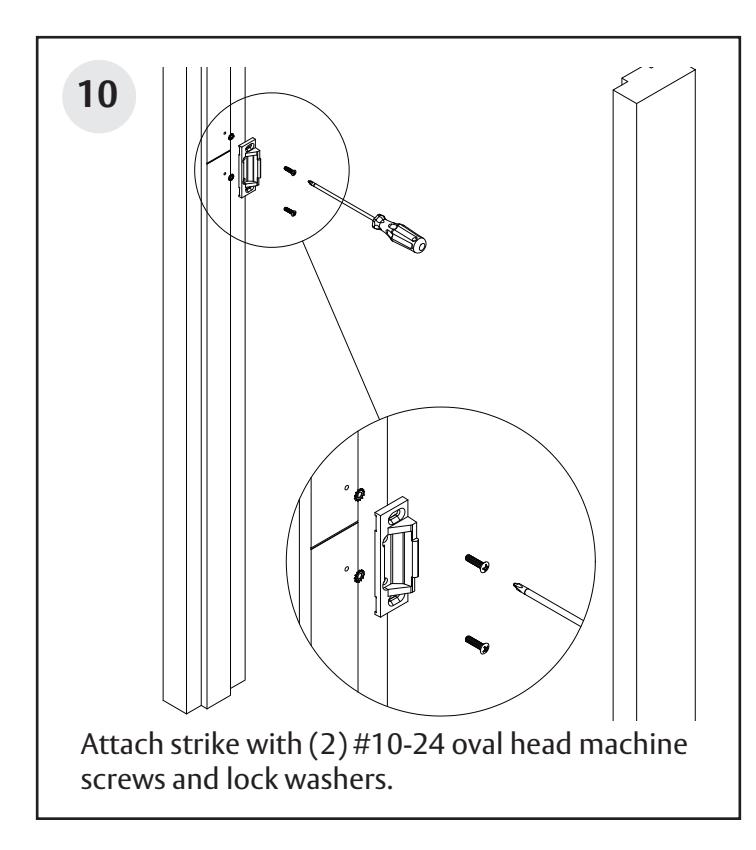
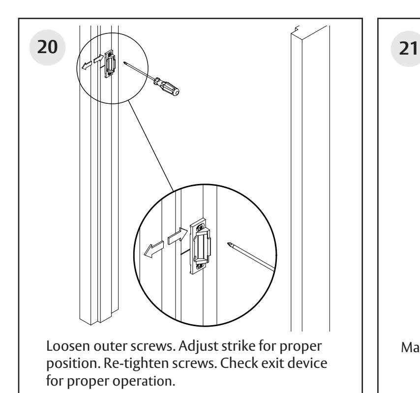
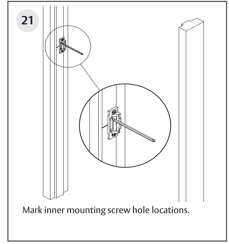
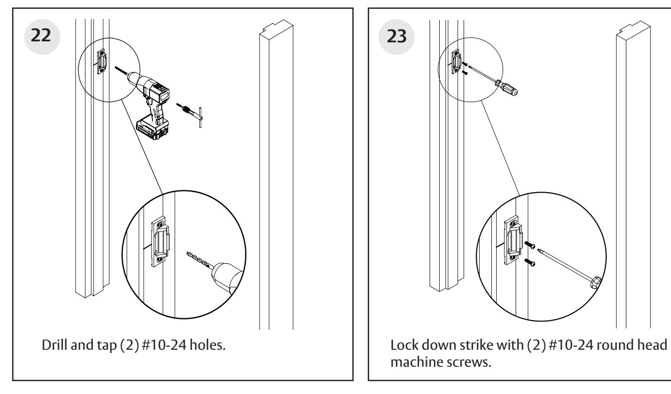
649 Strike
Rim Exit Device for 10T, 55T, 42, & 42T Functions
Installation Instructions
For installation assistance contact Corbin Russwin 1-800-543-3658 • techsupport.corbinrusswin@assaabloy.com
FM576 9/22
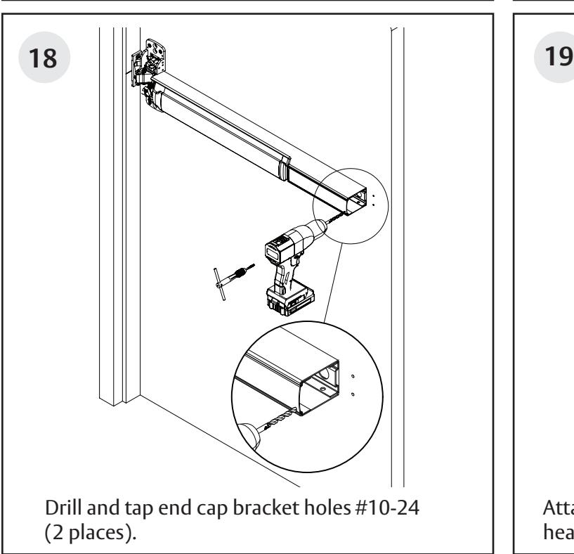
and cut out opening for chassis bell housing /
thumbpiece clearance (this side only).
Rim Exit Device for 10T, 55T, 42, & 42T Functions
Installation Instructions
used (this side only).
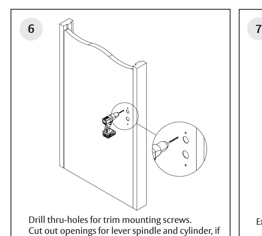
Extend rail horizontal centerline to frame. Install Strike
Rim Exit Device for 10T, 55T, 42, & 42T Functions

Rim Exit Device for 10T, 55T, 42, & 42T Functions
Installation Instructions
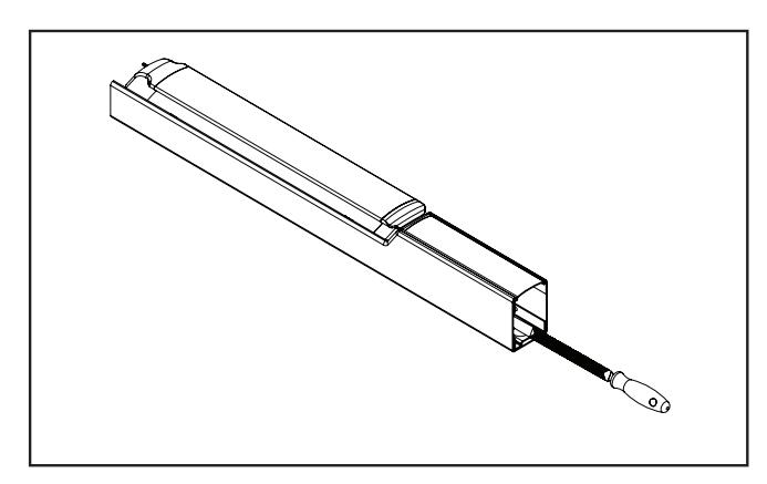
Rail cutting guide
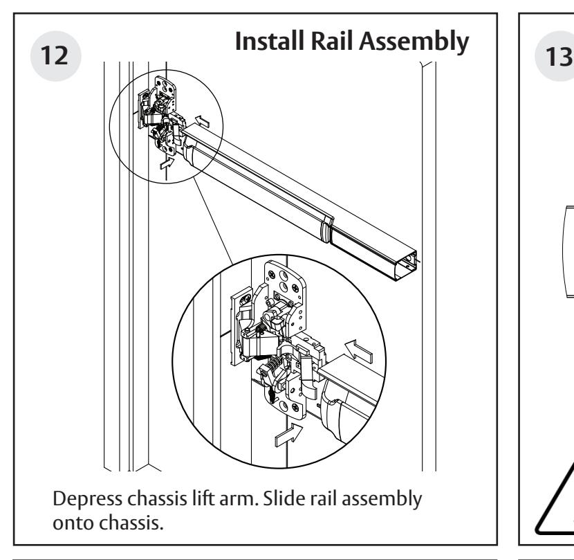
If the rail doesn't need to be cut, continue to page 10, step 12. If the rail must be cut, follow these steps on page 8 and 9:
Refer to the individual exit device installation instructions for rail cutting requirements / restrictions.
Instructions will vary based on device type and options.
• Determine cut off dimension "X" by subtracting 2-7/8" from dimension "Y". Mark cut off point on mounting rail. (See below.)
Do not cut closer than 1-5/8" from the the front edge of the rail insert.
| Information for Cutting Rails | |||
|---|---|---|---|
| Rail Sizes | Door Widths | ||
| Standard | Minimum | ||
| W032 | 32" | 24" | |
| W036 (Std.) | 36" | 33" | |
| W042 | 42" | 37" | |
| W048 | 48" | 43" | |
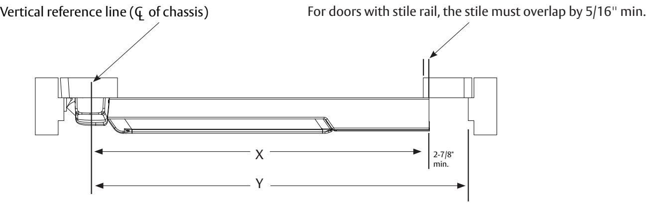
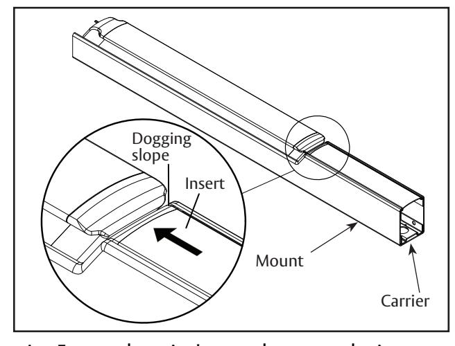
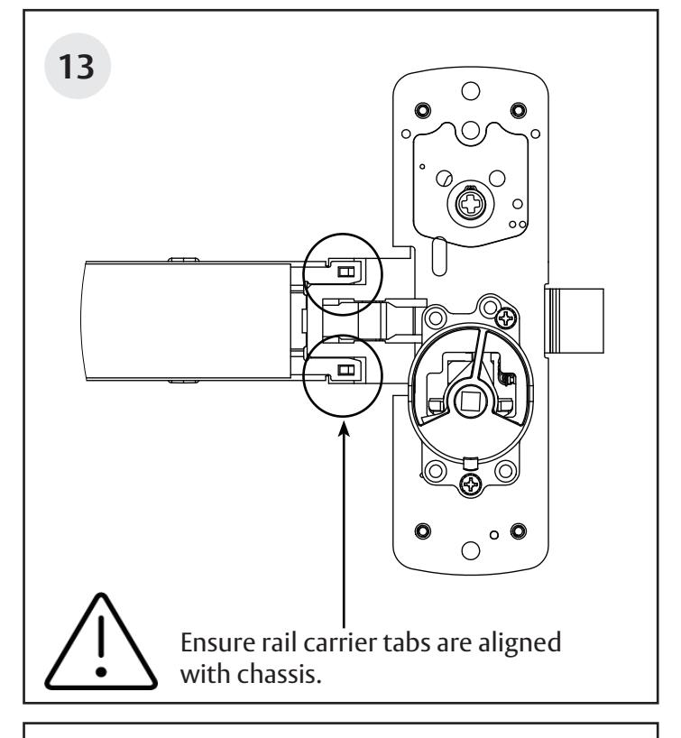
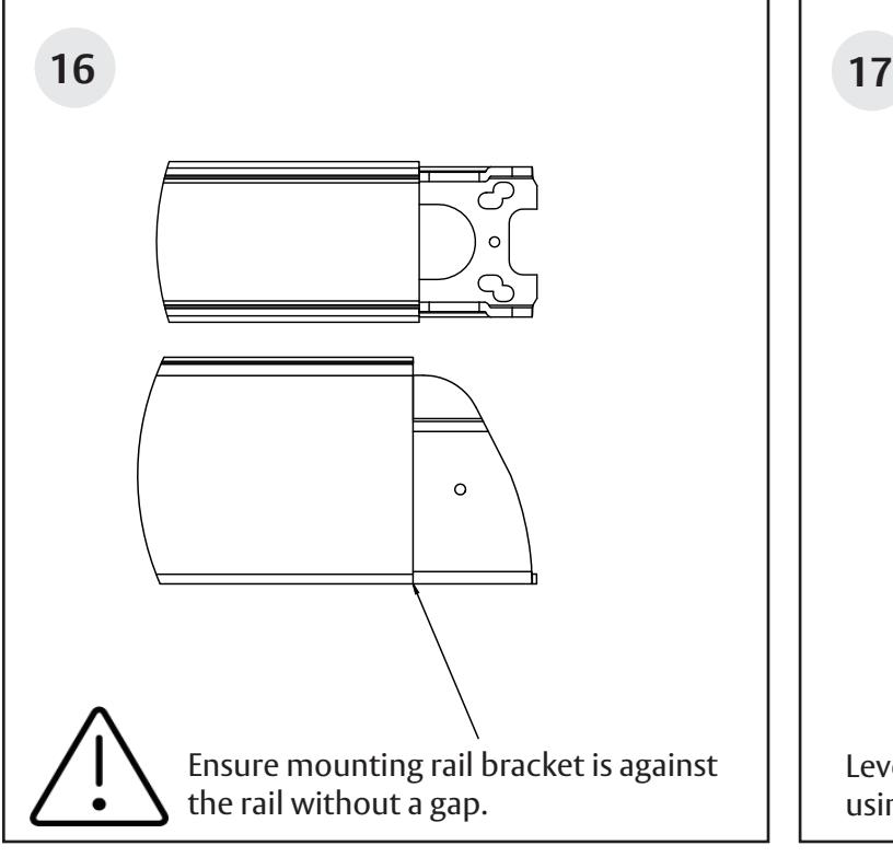
A. Ensure there isn't a gap between the insert and the dogging slope, and the carrier is flush with the mount.
B. Mark rail at the required cut length.
Rim Exit Device for 10T, 55T, 42, & 42T Functions
Installation Instructions
Rail cutting guide, continued.

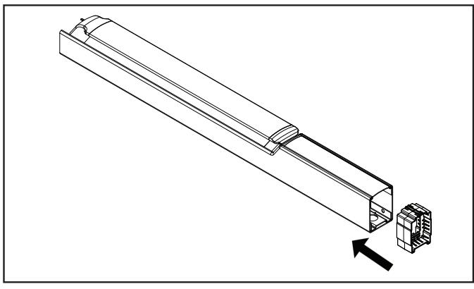
C. Ensure plastic insert support is installed under the cut line.

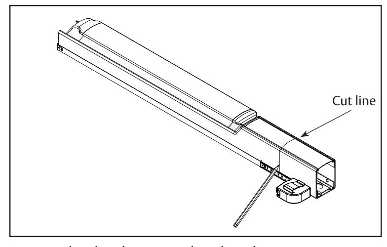
D. Wrap the rail and insert in masking tape, as shown.
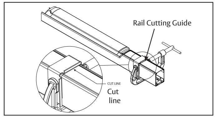
E. Place the rail cutting guide over the masking tape and align it with the cut line. Clamp the cut guide to the rail using a C-clamp.
F. Using a hack saw with a new blade or a chop saw with a metal cutting blade, cut the rail, ensuring that the blade stays pressed against the rail cutting guide.
G. Deburr and smooth all cut edges with a file.
Rim Exit Device for 10T, 55T, 42, & 42T Functions
Installation Instructions
Rim Exit Device for 10T, 55T, 42, & 42T Functions
Rim Exit Device for 10T, 55T, 42, & 42T Functions
Installation Instructions
Rim Exit Device for 10T, 55T, 42, & 42T Functions
Installation Instructions

42 Function
14
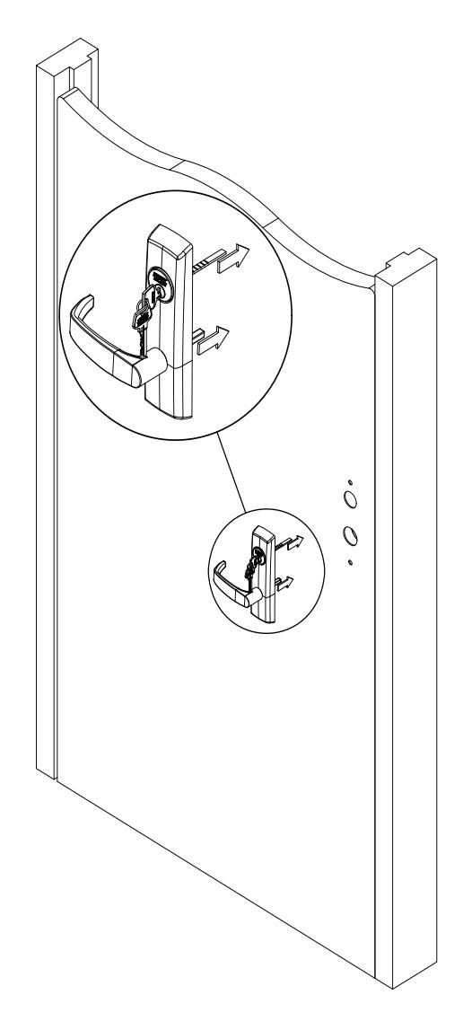
Insert trim. Ensure lever spindle aligns with bell housing hub and rim cylinder tailpiece aligns with upper spindle hub in chassis (if used).
Secure trim with (2) 1/4 - 20 flat head machine screws through chassis. If used, attach rim cylinder through chassis with screws provided with cylinder.
Rim Exit Device for 10T, 55T, 42, & 42T Functions
Installation Instructions
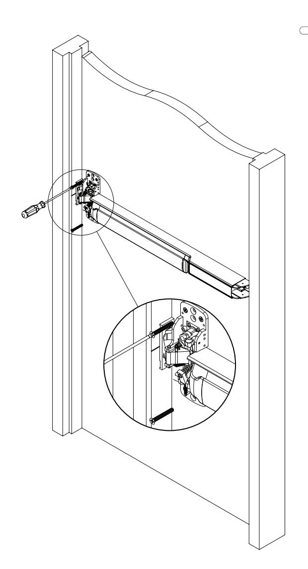
24a 42 10T, 55T, & 42T Functions Mount rim cylinder with (2) screws through chassis. 10T, 55T & 42T Function Rim Cylinder Install T33, T34, and T35 Thumbpiece Trim
Rim Exit Device for 10T, 55T, 42, & 42T Functions
Installation Instructions
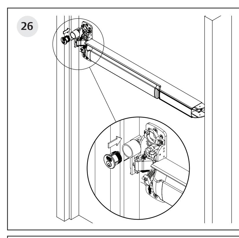
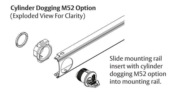
Insert mortise cylinder through blocking ring into cylinder support.
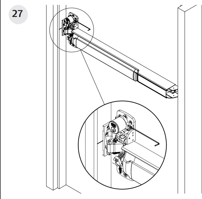
Tighten set screw with 5/64" wrench.
Rim Exit Device for 10T, 55T, 42, & 42T Functions

Rim Exit Device for 10T, 55T, 42, & 42T Functions

Rim Exit Device for 10T, 55T, 42, & 42T Functions