


Installation Instructions

PED4200/PED5200 Series Exit Devices
Weatherized Exit Device
Electrical Wiring and Wire Routing for:
- WM91 Prefix (Latch Monitor Switch)
- WM93 Prefix (Exit Trim Lever Monitor Switch)
- WM92 Prefix (Push Bar Signal Switch)

This product can expose you to lead which is known to the state of California to cause cancer and birth defects or other reproductive harm. For more information go to www.P65warnings.ca.gov.
Copyright © 2023, ASSA ABLOY Access and Egress Hardware Group, Inc. All rights reserved. Reproduction in whole or in part without the express written permission of ASSA ABLOY Access and Egress Hardware Group, Inc. is prohibited.
with optional connections
Installation Instructions

| TOC | Table of Contents |
|---|---|
| 1 | Function 3 |
| 2 |
General Description
3 |
| 3 | Specifications 3 |
| 4 | Weatherized Connector System Notes 4 |
| 5 | Wire Routing 5 |
| 6 | PED Series Device Installation and Wiring Overview 7 |
| 7 | WM91 Prefix (Latch Monitor Switch) - Exit Device to Frame Connection 8 |
| 8 | WM93 Prefix (Trim Monitor Switch) - Exit Device to Frame Connection 9 |
| 9 |
WM92 Prefix Push Bar (Signal Switch) - Exit Device to Frame Connection
10 |
Note: The WM92, WM91 and WM93 options are combined into this one instruction.
with optional connections
Installation Instructions

1 Function
- The WM92 prefix signal switch monitors the touch bar. When the rail is depressed or dogged, the switch is de-activated.
- The WM91 prefix latchbolt monitor switch provides positive indication of latchbolt extension or retraction when the push rail is depressed, dogged or if the latch bolt itself is depressed.
- WM93 prefix signal switch monitors the outside lever. When the lever is rotated, the switch is deactivated.
2 General Description
This instruction manual includes wiring instructions for all Premium Exit (PED) Series Weatherized Electrified Exits Options to ElectroLynx connector system. The correct wiring configuration must be selected depending on type and function of the product being installed. Refer to table of contents to select appropriate wiring instruction for product options being installed. Options/prefixes can be combined and wired together, as ordered.
3 Specifications
WM91, WM93, and WM92 switch contact rating: 1A max @ 30VDC
WM91 prefix (latch monitor switch)
WM93 prefix (exit trim lever monitor switch)
WM92 prefix (push bar signal monitor switch)

Caution: Disconnect all input power before beginning installation to prevent electrical shock and equipment damage. All wiring must comply with applicable local electrical codes, ordinances and regulations. Installer must be a trained, experienced service person.
with optional connections
Installation Instructions

4 Weatherized Connector System Notes
The system is designed to be installation friendly with quick connectors from the electric hinge through the door to the rail. Modification to wiring inside rail or at hinge receptacle will compromise water resistance. Do not cut / splice wires.
Important: The IP-67 weatherized plug and receptacle connectors are designed to mate and lock together as shown in the figure. Plug the connectors into each other with the locking mechanism aligned as indicated.
Do not force connectors on any other way.
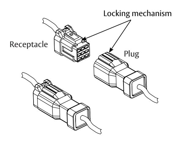
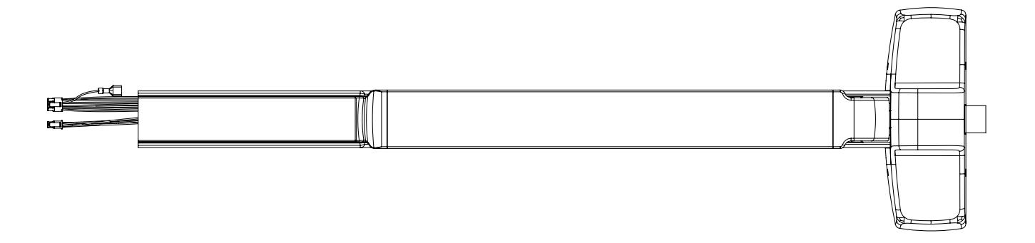
Example of latch head and trim connectors
These notes apply to all of the following devices concerning the installation and wiring to the Weatherized Connector System.
With new applications, a raceway harness with 8- and 4-pin connectors will be pre-installed inside door by ASSA ABLOY door manufacturer when specified during the ordering process. Raceway harness kits are also available for retrofit applications.
with optional connections
Installation Instructions

5 Wire Routing PED4200 OVERVIEW WM93 Lever Monitoring (if applicable) WM91 Connection
Step 2 . Secure trim . Make WM91 connectio . n Step 1 . Install chassis to rail . Route wires through door as shown .
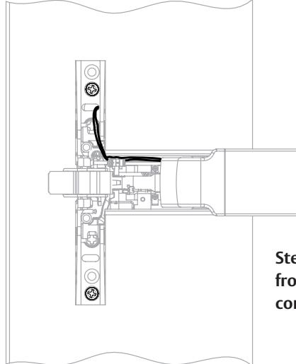
Step 3 . Pull additional wire slack through rail from insert end and tuck latch bolt monitor (WM91) connection into chassis .
with optional connections
Installation Instructions

5 Wire Routing - continued
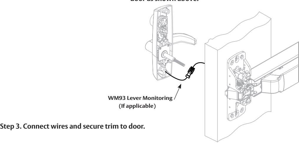
PED5200
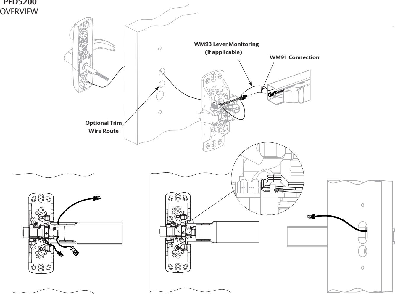
Step 1 . Install chassis and rail . Step 2 . Route trim wires through chassis and door as shown above .
Step 2A . Additional view
with optional connections
Installation Instructions

6
PED Series Installation and Wiring Overview
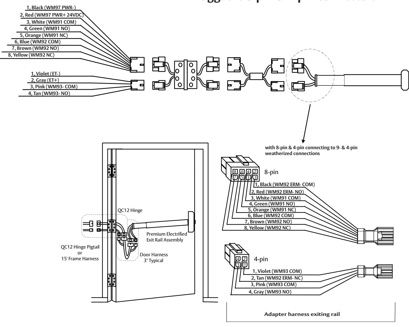
ElectroLynx System Wiring Options QC12 Hinge (12 wires) Pluggable 8-pin & 4-pin connectors
with optional connections
Installation Instructions

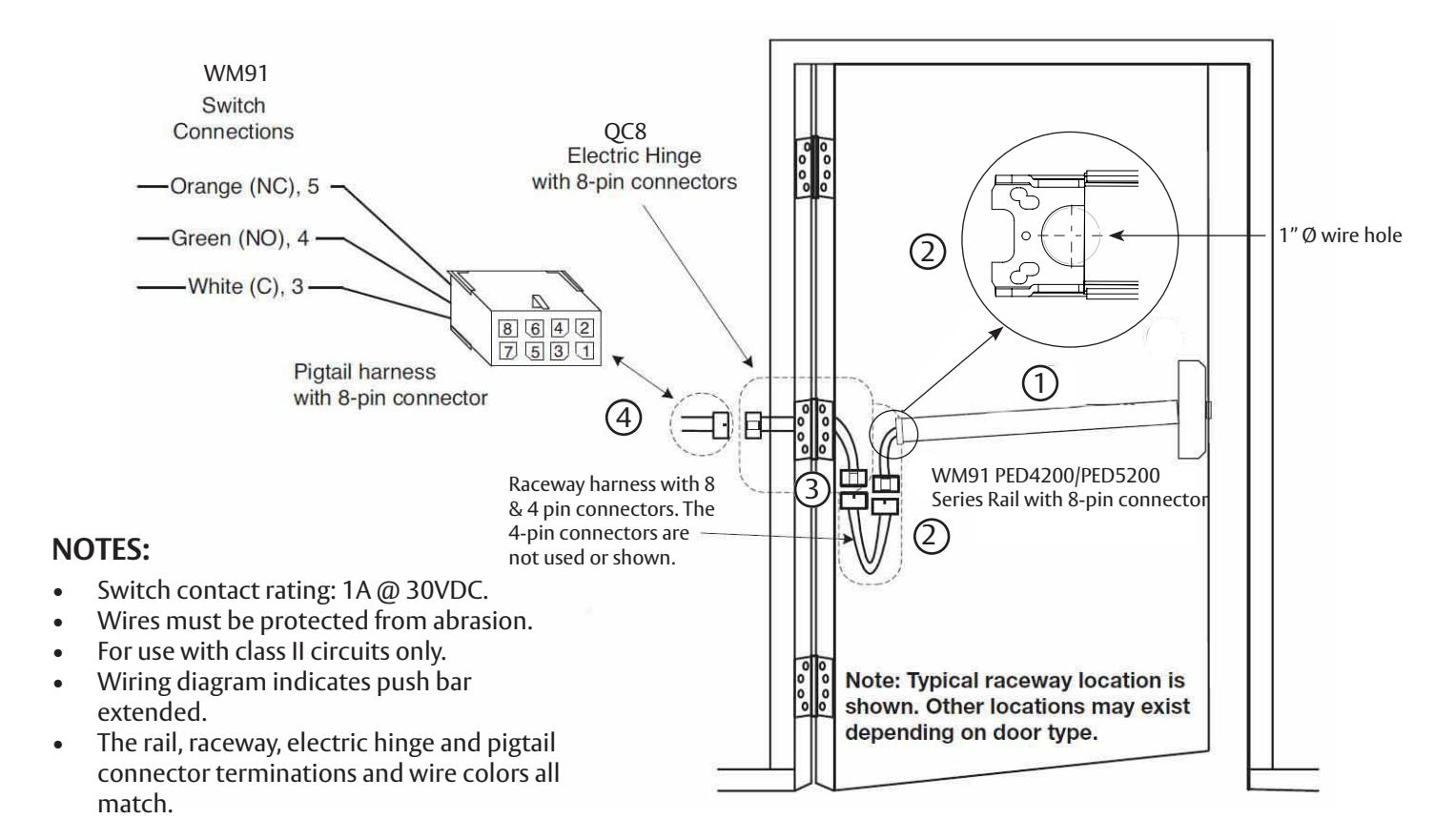
7 WM91 Prefix (Latch Monitor Switch) - Exit Device to Frame Connection
Installation Instructions:
1 Mount exit device per instruction sheet provided.
To insure trouble free operation, check that the push rail can be fully depressed. On vertical rod exit devices, check that the latch bolts do not go into hold back position until the push rail is fully depressed.
- Plug rail connector into raceway connector. Then feed through 1" hole in door. Install rail mounting bracket with two screws supplied. Ensure E-Lynx connection is stored within door. Install rail insert and end cap. 2
- Plug raceway connector into electric hinge connector, then feed through door prep. Mount electric hinge to door. 3
-
Go to (A) if wiring now. Go to (B) if wiring is to be done later. 4
- (A) Wire frame side wires to wires on pigtail harness as required using connectors allowed by local code. Plug pigtail harness connector into electric hinge connector. Feed harnesses through frame prep and mount electric hinge.
- (B) Plug pigtail harness connector into electric hinge connector. Feed harnesses through frame prep and mount electric hinge.
with optional connections
Installation Instructions

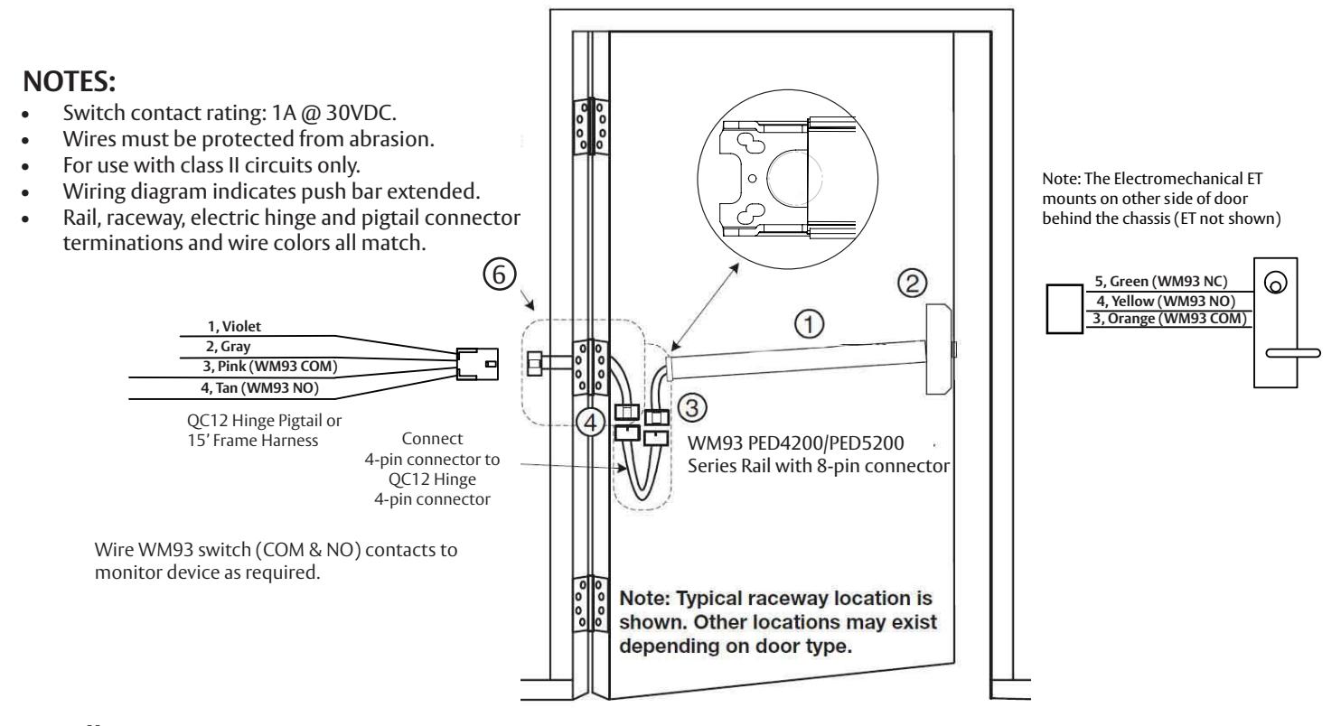
8 WM93 Prefix (Trim Monitor Switch) - Exit Device to Frame Connection
Installation Instructions:
- Mount exit device per instruction sheet provided. 1
- 2. From outside of door, route Electromechanical ET wire harness through chassis and door, then plug 3-pin connector into mating rail harness 3-pin connector.
- 3. Ensure wires are tucked in to avoid pinching wires by push bar or chassis mechanism.
- Plug rail connector into raceway connector. Then feed through 1" hole in door. Install rail mounting bracket with two screws supplied. Install rail insert and end cap. 4
- Plug raceway connector into electric hinge connector, then feed through door prep. Mount electric hinge to door. 5
-
Go to (A) if wiring now. Go to (B) if wiring is to be done later: 6
- (A) Wire frame side wires to wires on pigtail harness as required using connectors allowed by local code. Plug pigtail harness connector into electric hinge connector. Feed harnesses through frame prep and mount electric hinge.
- (B) Plug pigtail harness connector into electric hinge connector. Feed harnesses through frame prep and mount electric hinge.
- 7. Test lock WM93 trim lever monitor switch monitors lever movement. Switch changes state when lever is rotated.
with optional connections
Installation Instructions

9 WM92 Prefix Push Bar (Signal Switch) - Exit Device to Frame Connection
WM92 PED Series (Signal Switch) Installation and Wiring
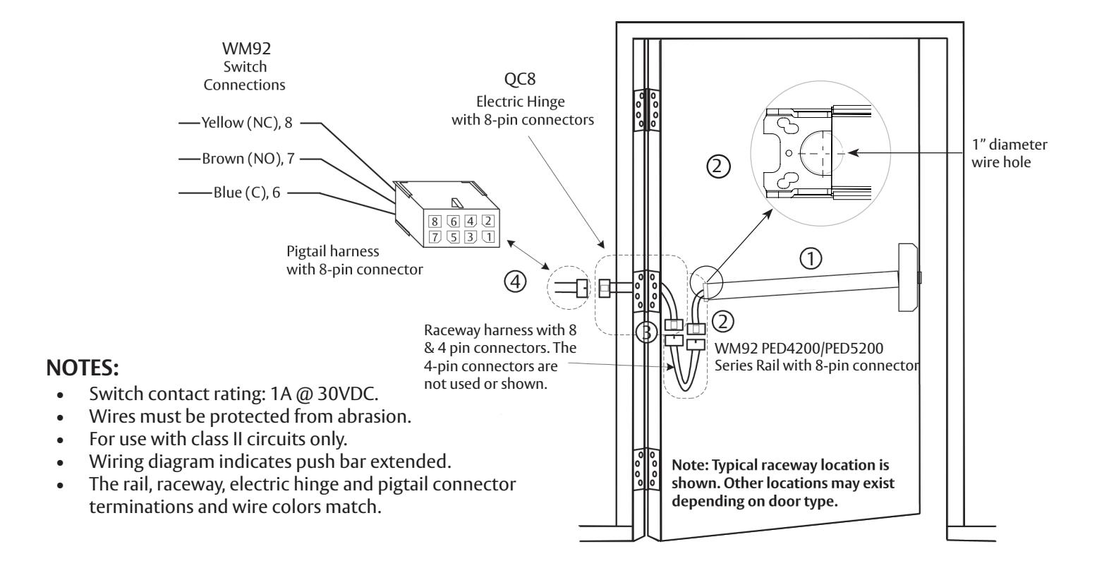
Installation Instructions:
1 Mount exit device per instruction sheet provided.
To insure trouble free operation, check that the push rail can be fully depressed. On vertical rod exit devices, check that the latch bolts do not go into hold back position until the push rail is fully depressed.
- Plug rail connector into raceway connector. Then feed through 1" hole in door. Install rail mounting bracket with two screws supplied. Ensure E-Lynx connection is stored within door. Install rail insert and end cap. 2
- Plug raceway connector into electric hinge connector, then feed through door prep. Mount electric hinge to door. 3
-
Go to (A) if wiring now. Go to (B) if wiring is to be done later. 4
- (A) Wire frame side wires to wires on pigtail harness as required using connectors allowed by local code. Plug pigtail harness connector into electric hinge connector. Feed harnesses through frame prep and mount electric hinge.
- (B) Plug pigtail harness connector into electric hinge connector. Feed harnesses through frame prep and mount electric hinge.
with optional connections
Installation Instructions


Corbin Russwin 225 Episcopal Road Berlin, CT 06037 Phone: 800-543-3658 Fax: 800-447-6714
corbinrusswin.com
Copyright © 2023 ASSA ABLOY Access and Egress Hardware Group, Inc. All rights reserved. Reproduction in whole or in part without the express written permission of ASSA ABLOY Access and Egress Hardware Group, Inc. is prohibited. Patent pending and/or patent - www.assaabloydss.com/patents. HID, iCLASS, and Edge are trademarks or registered trademarks of HID Global Corporation.