Installation Instructions

PED4000 / PED5000 Series with M61
Alarmed Exit Devices


This product can expose you to lead which is known to the state of California to cause cancer and birth defects or other reproductive harm. For more information go to www. P65warnings.ca.gov.
For installation assistance contact Corbin Russwin 1-800-543-3658 • techsupport.corbinrusswin@assaabloy.com

Attention Installer: Improper installation may result in damage to the product and void the factory warranty.
Alarmed Exit Devices
Installation Instructions


1 General Description
The M61 Alarmed Exit is designed for areas that require an alarm to sound upon exiting. Once armed, any push rail movement will activate the horn in the push rail. The horn will continue to sound for two minutes and then shut off automatically. The LED will fl ash indicating a violation has occurred.
Manual dogging is provided standard on non fi re rated devices.
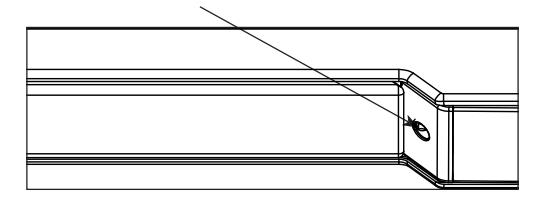
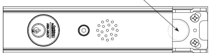
1" diameter hole(s) required for routing wires into the door when remote option(s) is used.
Notes:
- Installation must be performed by a trained service person.
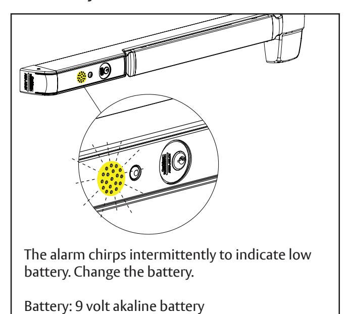
- Basic installation is 9V alkaline battery operated. For hardwired option use 709F989 / 709F999 Wiring harness See instruction sheet included with kit.
- Field cut rail assemblies are not allowed . Exit device must be ordered from the factory for specifi c door width.
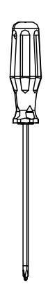
Tools Needed
Copyright © 2023, ASSA ABLOY Access and Egress Hardware Group, Inc. All rights reserved. Reproduction in whole or in part without the express written permission of ASSA ABLOY Access and Egress Hardware Group, Inc. is prohibited.
Alarmed Exit Devices
Installation Instructions

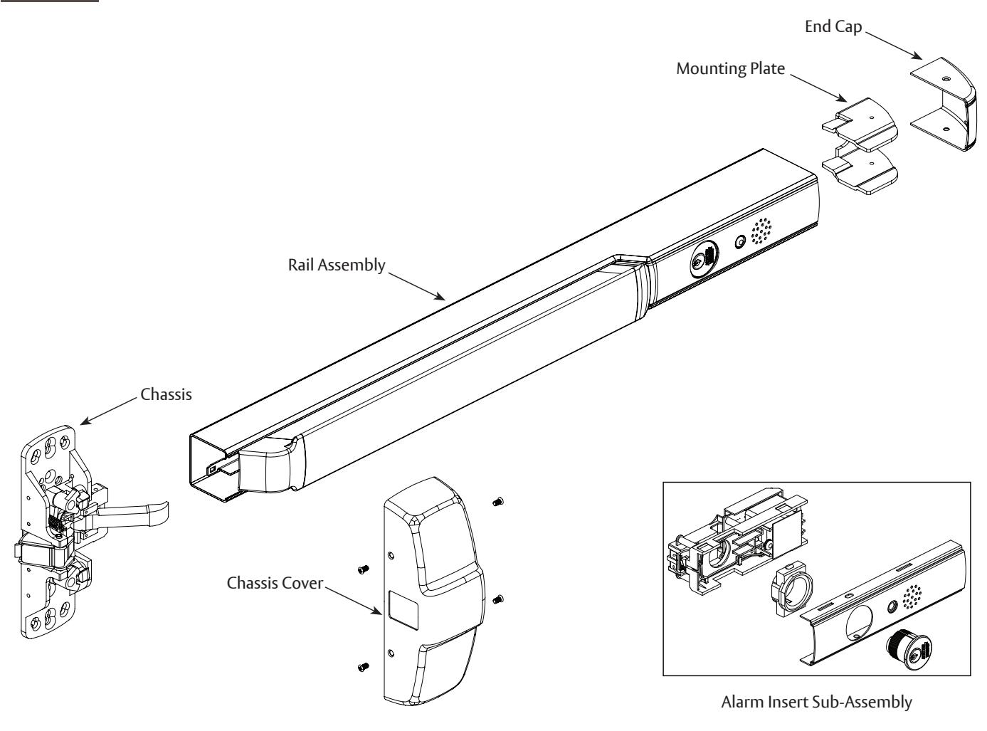
2 Miscellaneous Parts
Alarmed Exit Devices
Installation Instructions


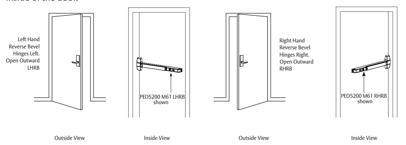
3 Door Preparation and Handing
Verify hand and bevel of door. Exit devices are always reverse bevel and are mounted on the inside of the door.
4 Cylinder Installation or Replacement
Note: If the cylinder is factory installed, go to Step 5 Installation Instructions (for retrofi t kit) on page 6.
Alarmed Exit Devices
Installation Instructions

4
Cylinder Installation or Replacement (continued)
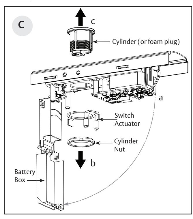
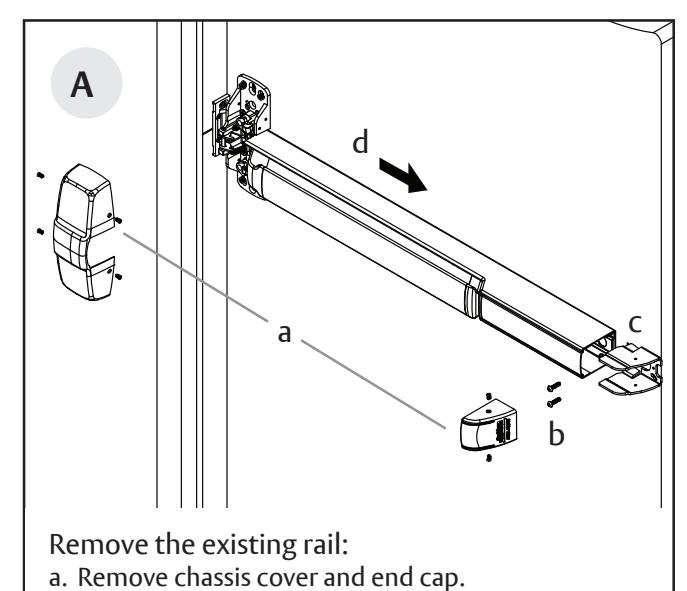
Remove the original cylinder (or foam plug, if ordered without the cylinder):
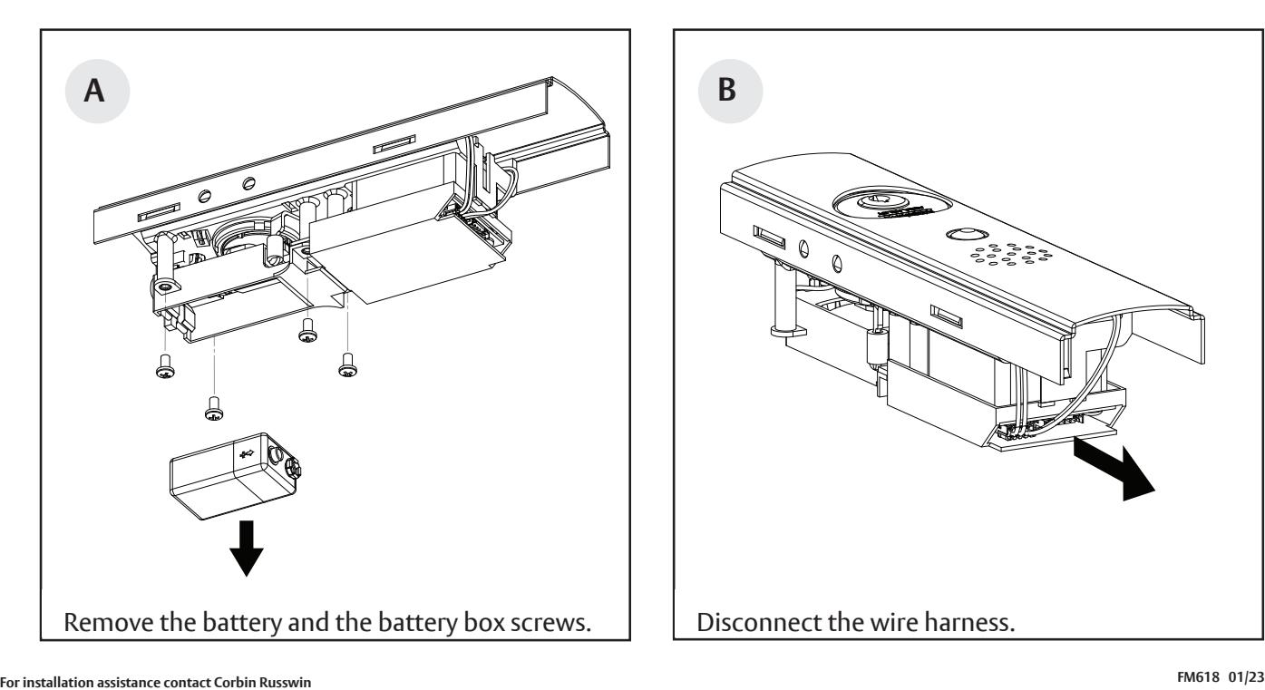
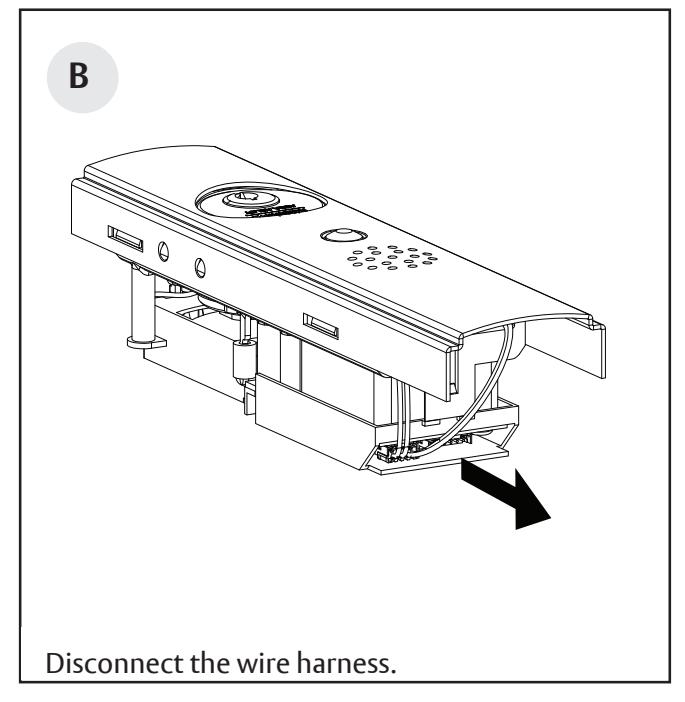
- a. Remove the battery box to expose the rear side of the cylinder side. Use caution not to damage any wire or switch when opening the battery box as it is still connected to the assembly with the battery terminal wires.
- b. Remove the cylinder nut and switch actuator.
- c. Remove the original cylinder (or foam plug).
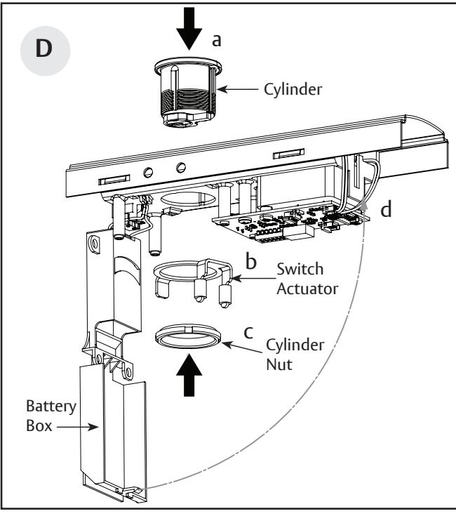
Install the new cylinder:
- a. Install the new cylinder to the insert subassembly with the keyway closest to the switch end.
- b. Reinstall the switch actuator with its legs on opposite sides of the toggle switch on the alarm board.
- c. Reinstall the cylinder nut, then tighten.
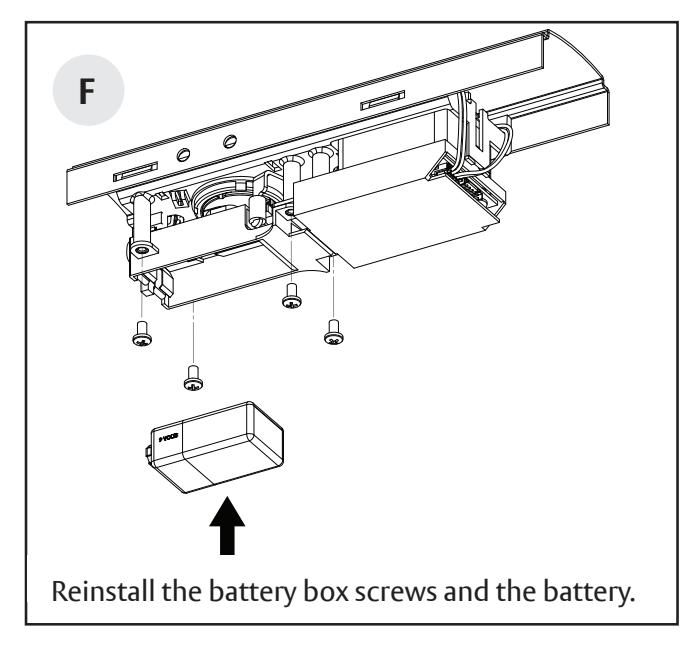
- d. Replace the battery box.
Alarmed Exit Devices
Installation Instructions

4 Cylinder Installation or Replacement (continued)
5 Installation Instructions (for retrofi t kit)
Note: If M61 option was ordered on a full device, refer to those instructions for the device installation. The following instructions are for alarm setup.
FM618 01/23 For installation assistance contact Corbin Russwin 1-800-543-3658 • techsupport.corbinrusswin@assaabloy.com
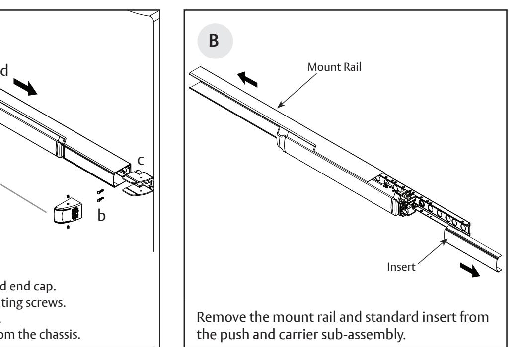
c. Remove the end bracket.
b. Loosen the chassis mounting screws.
d. Slide the rail assembly from the chassis.
Alarmed Exit Devices
Installation Instructions

5 Installation Instructions (for retrofi t kit, continued)
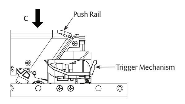
- a. Insert the trigger mechanism arms to the gap on both sides of the dogging cam (if present).
- b. Slide the trigger mechanism forward into the slot at the back of the dogging slope until it clicks into place.
- c. Press and release the push rail to verify that the trigger is properly installed.
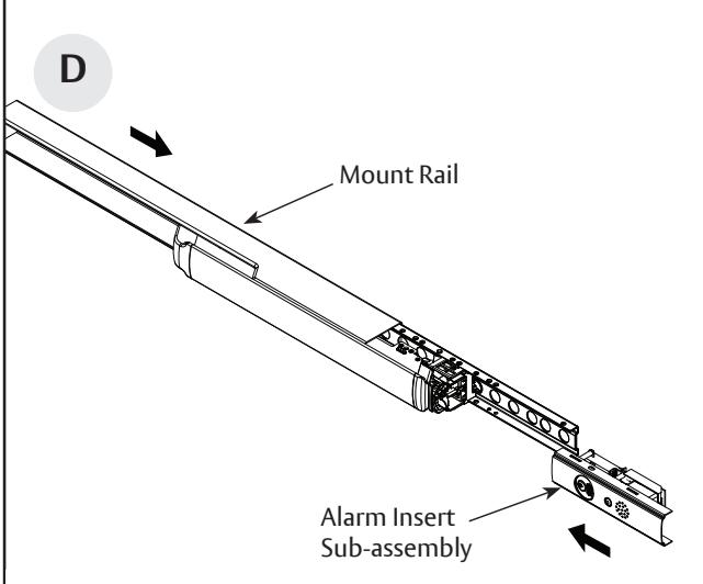
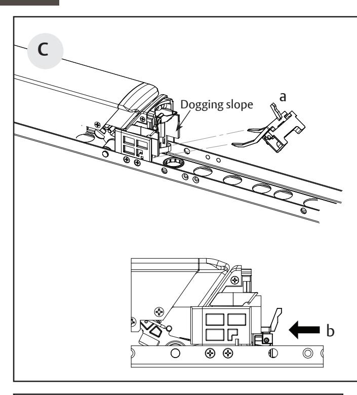
Slide the mount rail until it stops on the dogging slope, then install the alarm insert sub-assembly with the cylinder close to the push. Make sure to press the switch fi rmly against the trigger mechanism.
part without the express written permission of ASSA ABLOY Access and Egress Hardware Group, Inc. is prohibited.
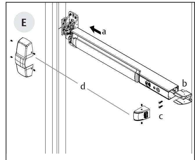
Reinstall the rail:
- a. Slide the rail assembly to the chassis.
- b. Reinstall the end bracket.
- c. Tighten the chassis mounting screws.
- d. Reinstall the chassis cover and end cap.
7
Alarmed Exit Devices
Installation Instructions


6 Alarmed Exit (M61) Standard Operating Instructions
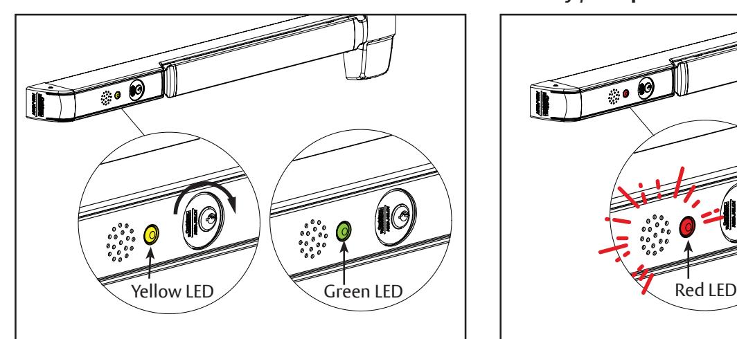
Turn the key clockwise. The LED will fl ash yellow (PASSAGE) for 15 seconds (default). A quick chirp will sound and the LED will fl ash green (ARMED) every 30 seconds. Signal indicates unit is armed.
NOTE : The unit is automatically armed 15 seconds after the unit is turned on. Field selectable settings listed on the next page.
To Arm Device Security / Tamper Violation
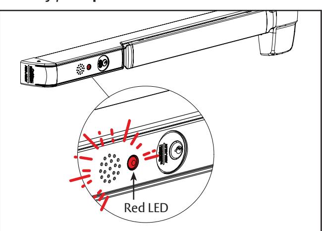
When ARMED, depressing the push rail will activate the alarm. The alarm will sound and the LED will fl ash red (VIOLATION). The alarm will continue for 2 minutes (default). After 2 minutes, the LED will fl ash red every 30 seconds until rearmed using the key. Turn the key counter clockwise to deactivate the alarm, then clockwise to rearm.
Low Battery Alert
Copyright © 2023, ASSA ABLOY Access and Egress Hardware Group, Inc. All rights reserved. Reproduction in whole or in part without the express written permission of ASSA ABLOY Access and Egress Hardware Group, Inc. is prohibited.
Alarmed Exit Devices
Installation Instructions

7 Optional Settings
These fi eld selectable switches can change the following functions:
Auto Alarm Reset
| Request to Exit/ |
|---|
| Passage Time Delay |
| DS3 | DS4 | Timer Reset |
|---|---|---|
| OFF | OFF | 2 minutes |
| OFF | ON | 5 minutes |
| ON | OFF | 10 minutes |
| ON | ON | Continuous* |
| DS1 | DS2 | Timer Reset |
|---|---|---|
| OFF | OFF | 7 seconds |
| OFF | ON | 10 seconds |
| ON | OFF | 15 seconds |
| ON | ON | 20 seconds |
| DS5 | |
|---|---|
| ON |
GREEN/ARMED
RED/VIOLATION YELLOW/ PASSAGE (DEFAULT) |
| OFF |
GREEN/VIOLATION
RED/ARMED YELLOW PASSAGE |
Recommend 3267 power supply and 546 wiring harness.
| DS6* | |||
|---|---|---|---|
| ON | Monitor relay is enabled (will activate when rail is violated) | ||
* Requires 709F989 / 709F999 wire harness. See optional 709F989 / 709F999 wiring instructions for more information.
Alarmed Exit Devices
Installation Instructions

Alarmed Exit Devices
Installation Instructions