


Installation Instructions

FE6600 and BL6600 Series
Muséo ® Levers Multi-Point Lock

This product can expose you to lead which is known to the state of California to cause cancer and birth defects or other reproductive harm. For more information go to www.P65warnings.ca.gov.
Multi-Point Lock
Installation Instructions

| TOC | Table of Contents | |
|---|---|---|
| 1 | Tools Required 2 | |
| 2 | Package Contents 3 | |
| 3 | Installation 4 | |
| a | Change Hand of Lock 4 | |
| b | Change Hand of Latch 4 | |
| c | Instructions for FE6600 and BL6600 Series Multi-Point Locks 5 | |
| d | Instructions for CE, RE1, and L Escutcheons 6 | |
| 1 | Tools Required |

Multi-Point Lock
Installation Instructions

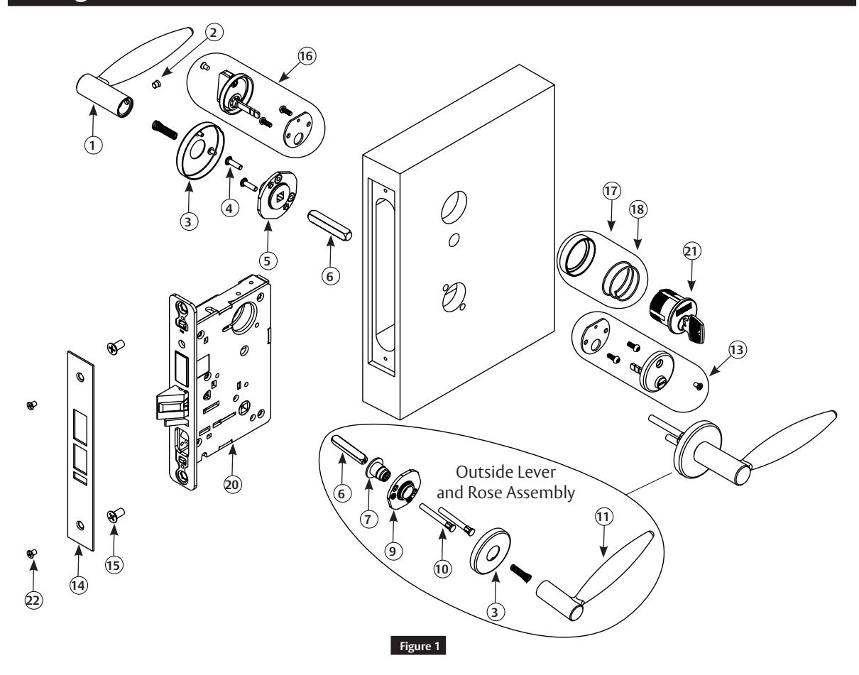
Package Contents
| 9 | Adapter and Plate Assembly | ||
| Outside Lever Handle - | |||
| 11 | consult factory | - | |
|
12
Turn Lever Assembly (130KB design) |
- | ||
| Figure 1 | Description | Qty. | Figure 1 | Description | Qty. |
|---|---|---|---|---|---|
| 1 | Inside Lever Handle - consult factory | 1 | 13 | Emergency Button Assembly (184KB) | 1 |
| 2 | Handle Set Screw 1/4-28 UNF | 1 | 14 | Outside Front | 1 |
| 3 | Rose - LN design | 2 | 15 | Machine Screw (#12-24 x 1/2") | 2 |
| 4 | Machine Screw #8-32 x 5/8" | 2 | 16 | Turn Lever Assembly (130 KB Design) | - |
| 5 | Inside Adapter and Plate Assembly | 2 | 17 | KB Cylinder Rosset (for 8200) | 1 |
| 6 | Spindle | 1 | 18 | Compression Spring | 1 |
| 7 | Cap Nut | 1 | 19 | Non-loosening Wave Spring | - |
| 8 | Washer | - | 20 | Lockbody | 1 |
| 9 |
Adapter and Plate Assembly
(LN design) |
1 | 21 | Cylinder | 1 |
| 10 | Mounting Post | 2 | 22 | Machine Screw (#8-32 x 1/4") | 2 |
* All trim components vary by function number. Refer to separate instruction sheet for trim one-side functions.
Multi-Point Lock
Installation Instructions

3 Installation
a Change Hand of Lock
Note:
Red surface of locking piece must face secure (keyed/locked) side of door.
To rotate locking piece:
- 1. Position lockbody with red surface of locking piece visible.
- 2. Insert blade type screwdriver into locking piece slot to rotate locking piece.
- 3. Push locking piece toward back of lock body and rotate 180° until RED surface shows on opposite side.
Note:
Red color indicates locked side of door.
b Change Hand of Latch
Note:
Beveled surface of latch must face strike. Deadlatch is self-adjusting.
To change hand of latch:
- 1. Insert flat blade screwdriver into spade shaped slot. ( Figure 4 )
- 2. Rotate screwdriver 90° to push latch out until back of latch clears lock front; rotate latch 180°. Latch will re-enter lockbody.
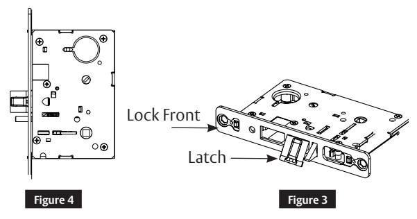
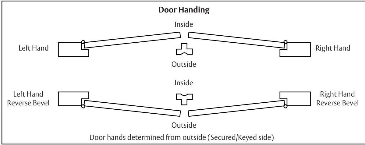
Figure 5
Multi-Point Lock
Installation Instructions

3 Installation (continued)
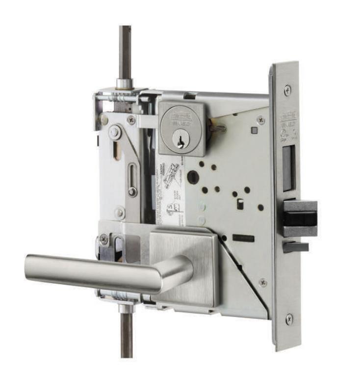
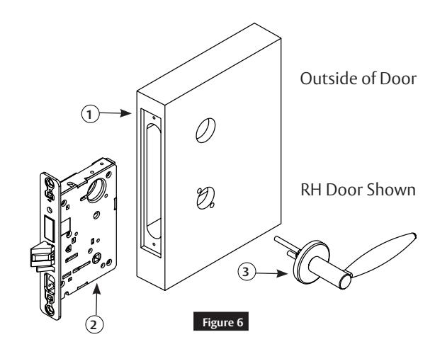
c Instructions for FE6600 and BL6600 Series Multi-Point Locks
Important: Check template 4740 to prep door for function holes, size, and location.
- 1. Verify strike location according to template.
- 2. Clean out door pocket and door edge of any debris.
- 3. Make sure the handing of the lock (latch and locking piece) match the handing of the door.
- 4. Slide lock into the door and hold.
- 5. Slide outside lever and rose assembly (or lever and escutcheon assembly) through the door; lock body and hold.
Note:
Keep door open while installing lock. If installing lever onto only one side of the door, see separate instruction sheet.
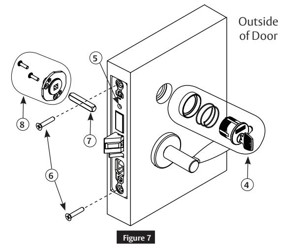
- 6. Assemble keyed cylinder first through narrow end of spring and then wider opening of collar (or escutcheon).
- 7. Assemble onto door by threading into lock until cylinder face is flush with collar edge. Pulling key slightly out of cylinder will help when threading cylinder inward.
Note:
Corbin Russwin logo must be horizontal and on upper portion of cylinder face.
- 8. Tighten cylinder clamp screw with #2 Phillips screwdriver.
- 9. Secure lock in door with two (2) #12 x 1-1/4" wood screws or #12-24 x 1/2" machine screws. Do NOT tighten completely at this time.
- 10. Slide spindle into lockbody hub.
- 11. Slide adapter and plate assembly over spindle and secure with two (2) #8-32 screws.
Installation Instructions

3 Installation (continued)
c Instructions for FE6600 and BL6600 Series Multi-Point Locks (continued)
- 12. Align posts in rose with holes in adapter and plate assembly, and press on until rose is tight against door face.
- 13. Attach inside lever and secure with 1/8" Allen wrench.
- 14. Assemble thumbturn/emergency release (if provided) according to instructions on bag.
- 15. Check for proper lock operation by function prior to closing door.
- 16. Tighten two lockbody screws completely.
- 17. Attach outside front with two (2) #8-32 x 1/4" flat head screws.

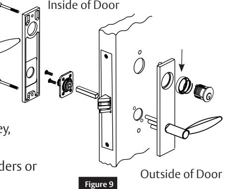
d Instructions for CE, RE1, and L Escutcheons
Through-bolt the inside escutcheon to the outside escutcheon with two screws #8-32 x 1-7/8".
Notes:
- Screw heads should be visible on inside escutcheon.
- Removable core or interchangeable core cylinders require a control key (a key stamped with "C") to remove and install the inner cylinder core. This is not standard; must be requested separately. If requesting 1-bitted control key, specify 113511 cut.
- Cylinder collar(s) are required for functions with two (2) cylinders or cylinders longer than # 41 (1-1/8"). ( Figure 9 )

Multi-Point Lock
Installation Instructions


Corbin Russwin, Inc. 225 Episcopal Road Berlin, CT 06037 USA Phone: 800-543-3658 Fax: 800-447-6714 www.corbinrusswin.com