


Installation Instructions

ED4000 & ED5000 Series
Motorized Electric Latch Retraction (MELR) Retrofi t Upgrade
Exit Devices

This product can expose you to lead which is known to the state of California to cause cancer and birth defects or other reproductive harm. For more information go to www.P65warnings.ca.gov.
MELR Retrofi t Upgrade
Installation Instructions

| TOC | Table of Contents | |
|---|---|---|
| 1 | Latch Retraction Pin3 | |
| 2 | 782 Power Controller Replacement3 | |
| 3 | MELR Replacement Kits4 | |
| 4 | Retrofi tting to the MELR4 |
MELR Retrofi t Upgrade
Installation Instructions

1 Latch Retraction Pin
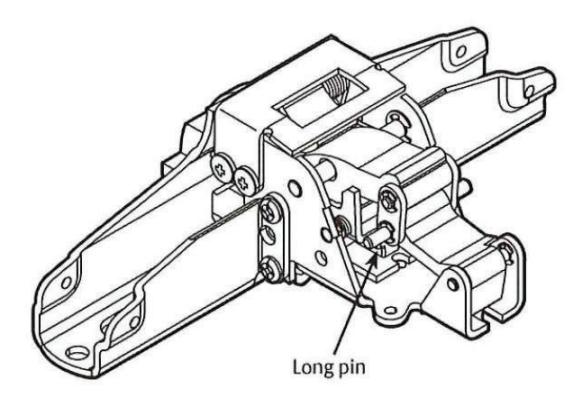
Latch Retraction Pin [Beginning April 2015 (15/15)]
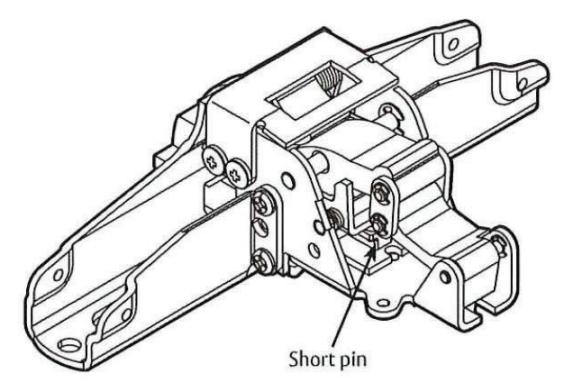
Latch Retraction Pin [Prior to April 2015 (15/15)]
Devices with short pins CANNOT be upgraded. A new latch assembly must be ordered to upgrade to MELR.
NOTE: A label with a date code is located on the front face of the latch assembly.
Important:
- Latch assemblies prior to April 2015 (with short pins) must be replaced.
- Latch assemblies manufactured from April 2015 to present (with long pins and date code: 17/15) can be retrofitted.
2 782 Power Controller Replacement
The 782 Power Controller is not compatible with the MELR option on the Corbin ED5000 & ED4000 Series Exit Device. In order to duplicate the functionality of the controller, a power supply with a timer is required for the application. Please contact your local ASSA ABLOY Door Security Solutions sales team member for more information.
MELR Retrofi t Upgrade
Installation Instructions

3 MELR Replacement Kits
| Model # | Product Description |
|---|---|
| CRMELR-36 | ED5000 36" MELR Device Assembly Kit |
| CRMELR-36-M93 | ED5000 36" MELR Device Assembly Kit with M93 Trim Monitoring Option |
| CRMELR-36-M107 | ED5000 36" MELR Device Assembly Kit with M107 Windstorm Option |
| CRMELR-36-M93-M107 |
ED5000 36" MELR Device Assembly Kit with M93 Trim Monitoring and M107
Windstorm Option |
| CRMELR-38 | ED4000 36" MELR Device Assembly Kit |
| CRMELR-38-M93 | ED4000 36" MELR Device Assembly Kit with M93 Trim Monitoring Option |
| CRMELR-48 | ED4000 and ED5000 48" MELR Device Assembly Kit |
| CRMELR-48-M93 |
ED4000 and ED5000 48" MELR Device Assembly Kit with M93 Trim Monitoring
Option |
| CRMELR-48-M107 | ED5000 48" MELR Device Assembly Kit with M107 Windstorm Option |
| CRMELR-48-M93-M107 |
ED5000 48" MELR Device Assembly Kit with M93 Trim Monitoring and M107
Windstorm Option |
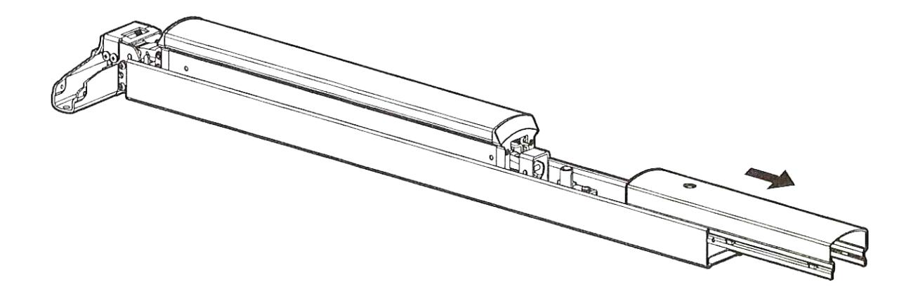
4 Retrofi tting to the MELR
- a Remove the existing carrier assembly from the door.
- b Slide the end cover off of the carrier assembly. Save the mounting hardware.
Installation Instructions

- 4 Retrofi tting to the MELR, continued
- c Remove the touch bar end plate with a T20 Torx screwdriver.
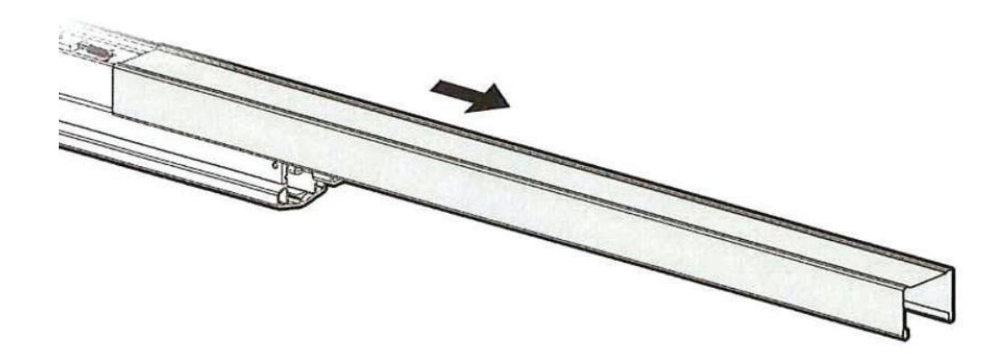
d Slide the cover off of the carrier assembly.
e Turn the carrier assembly over and slide the bottom of the carrier cover off of the carrier assembly.
MELR Retrofi t Upgrade
Installation Instructions

4 Retrofi tting to the MELR, continued
f
Remove the trim slide, wire protector, and latch assembly, as required for the carrier assembly.
For M94 (solenoid) carrier assemblies:
• Remove the four (4) screws holding the trim slide, latch assembly, and connecting slide in place. See Figure 1 on the next page.
For Mechanical carrier assemblies:
• Remove the three (3) screws holding the trim slide and latch assembly in place. See Figure2.
For Mechanical or M94 with M91 carrier assemblies:
- Remove the screws holding the trim slide, wire protector, and latch assembly in place. See Figure 3 Notes:
- Mechanical with M91 carrier assemblies require the removal of three screws. See Figure 2.
- Mechanical carrier assembles do not have a threaded rod and latch assembly.
- Cut the connector off of the end of the switch wire and fit the wire through the grommet in the carrier so the latch assembly can be removed. See Figure 4.
For Mechanical or M94 with M92 carrier assemblies:
- Remove the screws holding the trim slide, latch assembly, and connecting slide in place. See Figure 1. Notes:
- Mechanical with M92 carrier assemblies require the removal of three screws. See Figure 2.
- Mechanical carrier assembles do not have a threaded rod and latch assembly.
For Mechanical or M94 with M93 carrier assemblies:
• Remove the screws holding the trim slide and latch assembly in place. See Figure 1.
Notes:
- —The M93 Switch doesn't need to be removed. A new switch is included with the device retrofitting kit.
- —Mechanical with M93 devices require the removal of the three screws. See Figure 2.
- —Mechanical carrier assemblies do not have a threaded rod and latch assembly
.
For Mechanical or M94 with M91 and M92 carrier assemblies:
- Remove the screws holding the trim slide, wire protector, latch assembly, and connecting slide in place. See Figure 3.
- Cut the connector off of the end of the switch wire and fit the wire through the grommet in the carrier so the latch assembly can be removed. See Figure 4.
Notes :
- —Mechanical with M91 and M92 devices require the removal of three screws. See Figure 2.
- —Mechanical carrier assemblies do not have a threaded rod and latch assembly.
MELR Retrofi t Upgrade
Installation Instructions

4 Retrofi tting to the MELR, continued
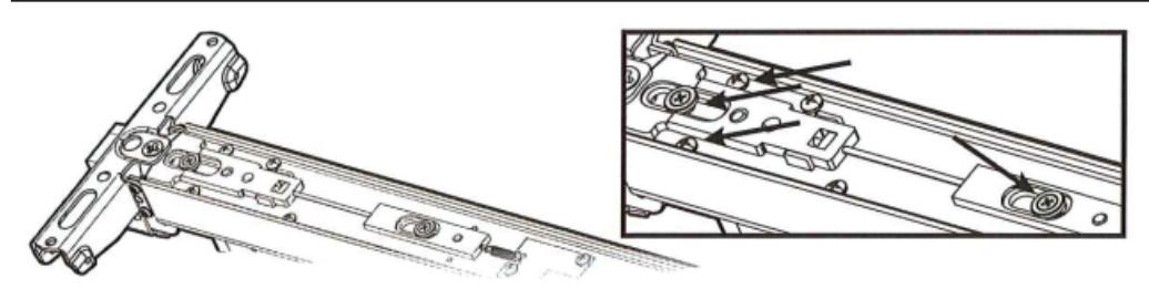
Figure 1 Four-screw removal (M94 base device)
Note: If a spring is attached to the latch assembly, carefully disconnect the spring before removing the latch assembly.
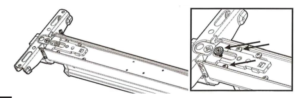
Figure 2 Three-screw removal (Mechanical base device)
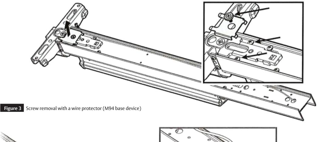
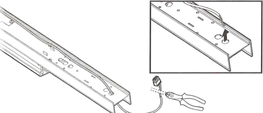
Figure 4 Cutting the connector
7
MELR Retrofi t Upgrade
Installation Instructions

4 Retrofi tting to the MELR, continued
g Unscrew the threaded rod from the trim slide (M94 only).
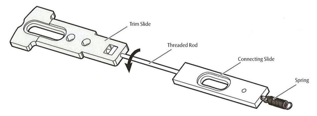
- Keep the trim slide.
- Discard the threaded rod, the connecting slide, and the spring (as applicable).
For installation assistance contact Corbin Russwin
h Remove the switch and bracket, if applicable.
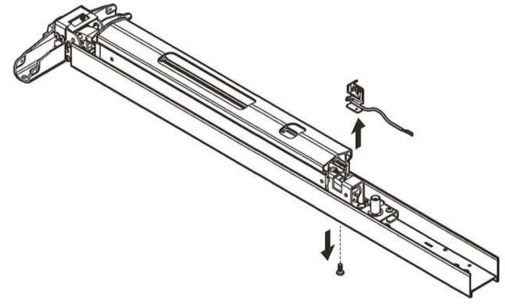
For Mechanical or M94 with M92 carrier assemblies:
• Remove the screw on the bottom of the existing carrier assembly to release the switch and bracket.
For Mechanical or M94 with M91 & M92 carrier assemblies:
• Remove the screw on the bottom of the existing carrier assembly to release the switch and bracket.
MELR Retrofi t Upgrade
Installation Instructions

4 Retrofi tting to the MELR, continuedr.
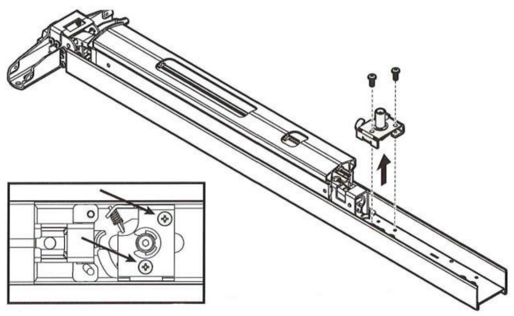
i If the device has a mechanical dogging assembly, remove the assembly by unscrewing the two screws holding it to the device.
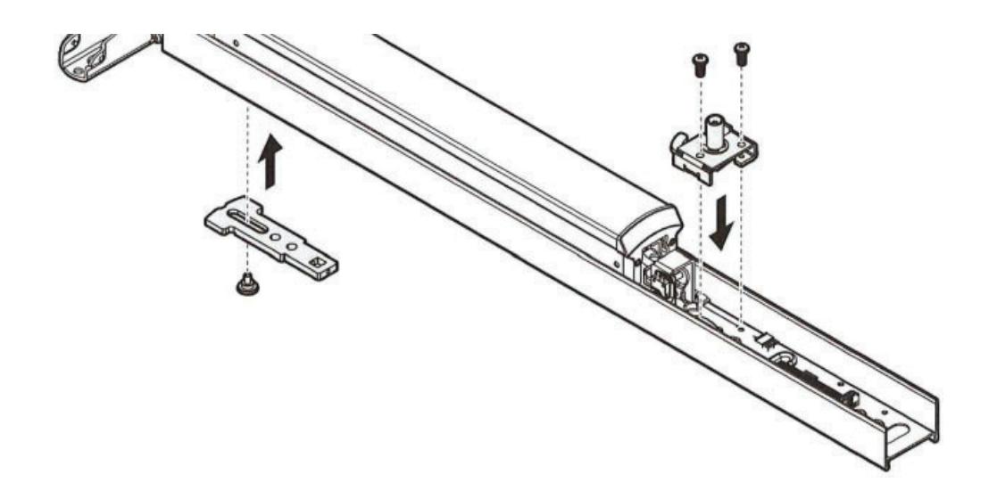
j Move the trim slide, touchbar cover, touchbar end plate, and the mechanical dogging assembly to the new MELR device.
Installation Instructions

4 Retrofi tting to the MELR, continued
k Test the mechanical dogging assembly.
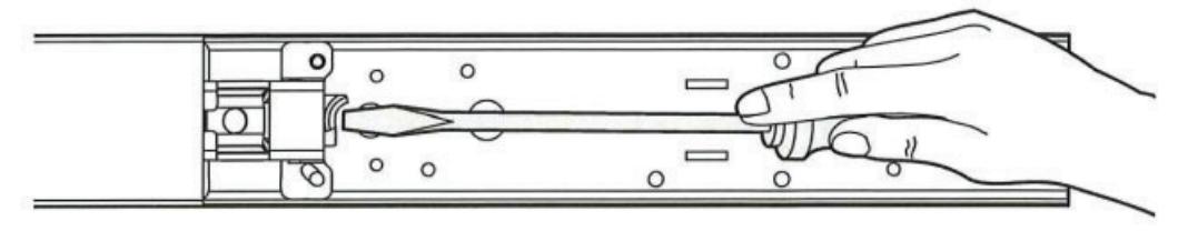
If the assembly does not have the proper latch retraction.
- Remove the dogging assembly:
- Adjust the retraction level by gently prying the latch hook with a screwdriver.
- Reinstall the dogging assembly.
- Test and adjust the latch retraction, as needed.
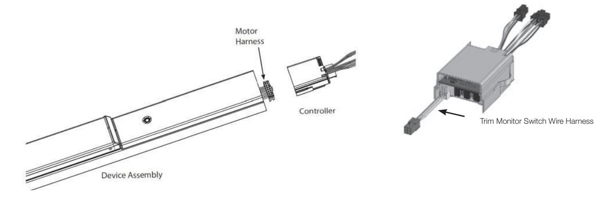
l Connect the motor and jumper harness, if applicable.
For Mechanical or M94 with M91 devices:
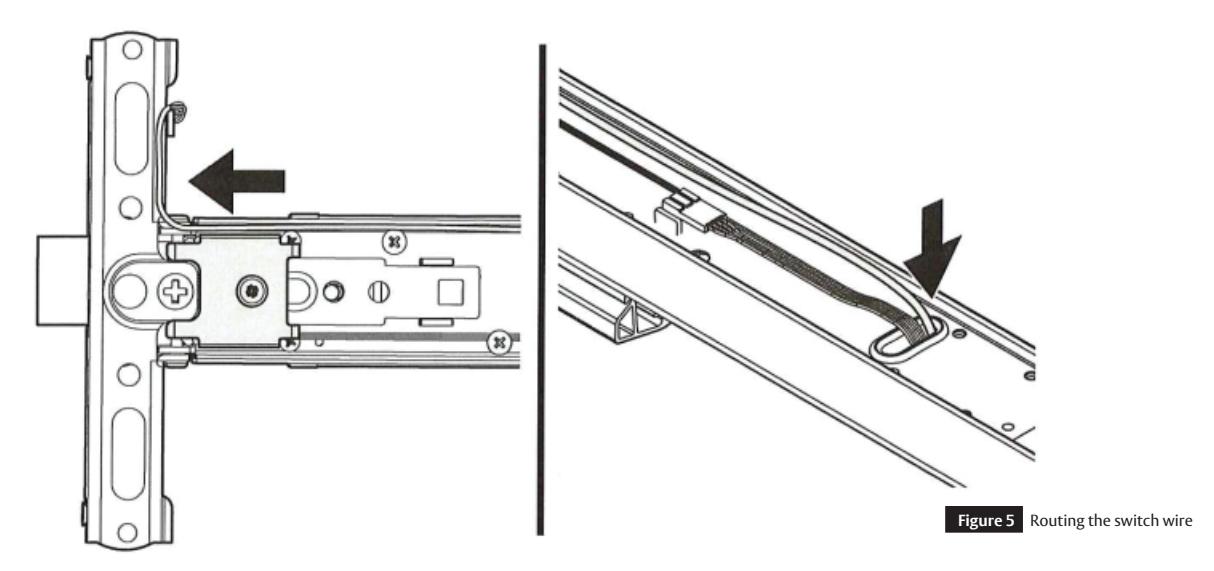
- Route the switch wire around the wire protector and through the grommet in the carrier. See Figure 5.
- Cut the switch wire 2" past the grommet.
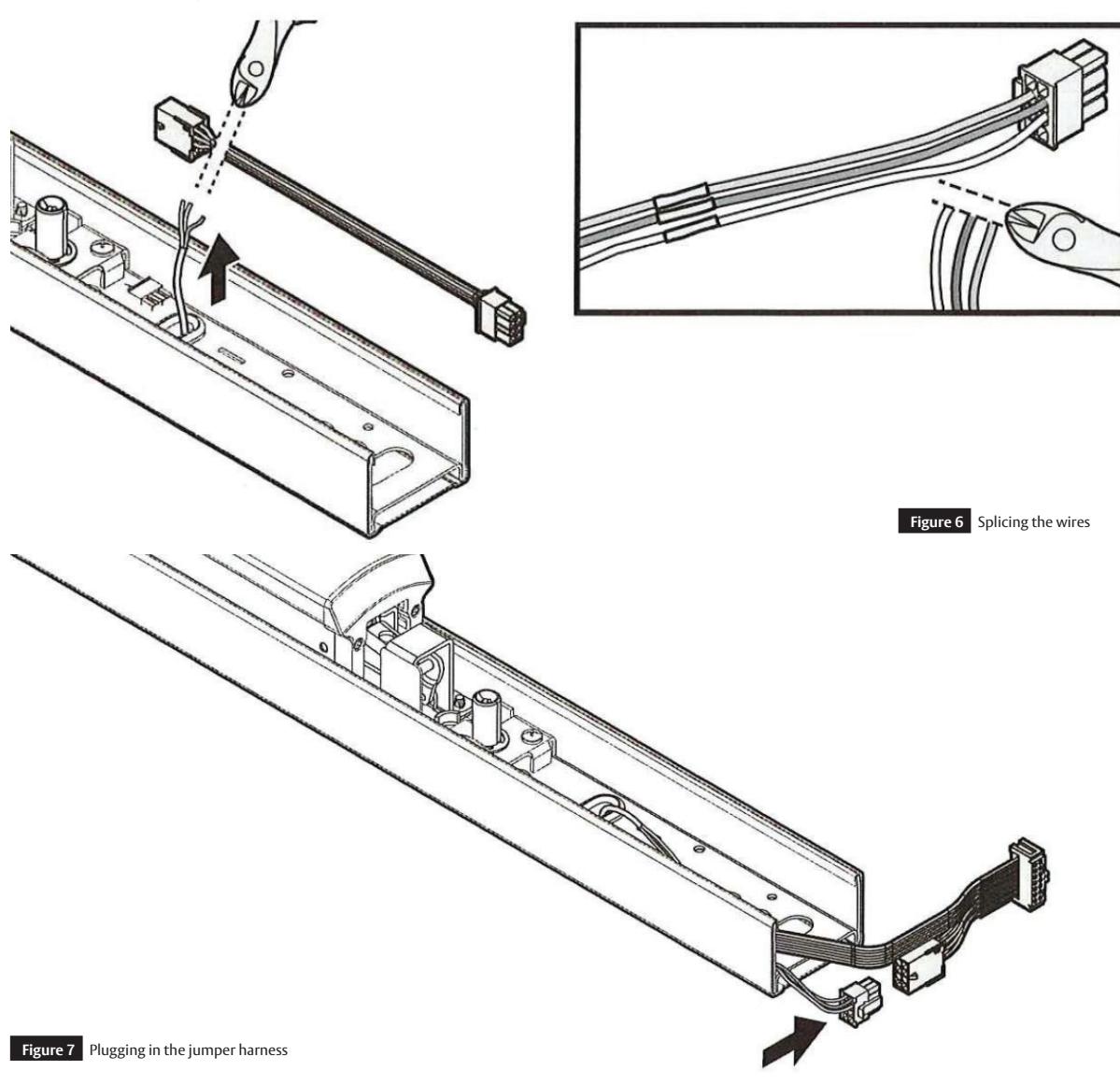
- Cut the jumper harness (p/n 727F509 included), leaving enough length to splice the jumper harness to the switch wires and also plug into the motor harness. See Figure 6 on the next page.
Note:
- Verify the connector being cut prior to cutting it off.
- Splice the switch wires to the matching color wires on the jumper harness and secure with the wire nuts provided. See Figure 6:
- Plug the jumper harness into the motor harness. See Figure 7 on the next page.
For Mechanical or M94 with M92 devices:
- Install the M92 switch. Refer to Section 4H "Remove the Switch and Bracket, if applicable" on page 7.
- Connect the switch wire to the motor harness. If required for length, use the provided jumper harness (p/n 727F509). See Figure 7.
FM486 09/20
Installation Instructions

4 Retrofi tting to the MELR, continued
l Connect the motor and jumper harness, if applicable, continued.
For Mechanical or M94 with M91 & M92 devices:
- Route the switch wire around the wire protector & through the grommet in the carrier. See Figure 5 on the previous page.
- Cut the switch wire 2" past the grommet.
- Cut the jumper harness (p/n 727509), leaving enough length to splice the jumper harness to the switch wires and also plug into the motor harness. See Figure 6.
Note:
- Verify the connector being cut prior to cutting it off.
- Splice the switch wires to the matching color wires on the jumper harness and secure with the wire nuts provided. See Figure 6:
- Plug the jumper harness into the motor harness. See Figure 7.
Installation Instructions

4 Retrofi tting to the MELR, continued
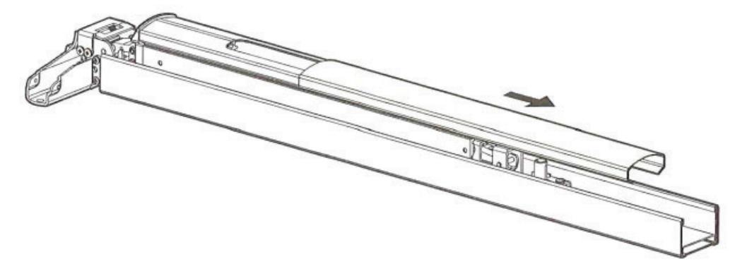
m Slide the carrier cover onto the device.
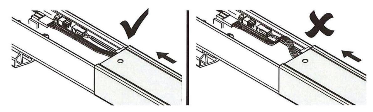
• The wires must lay flat when moving the carrier cover.
n Install the wire protector.
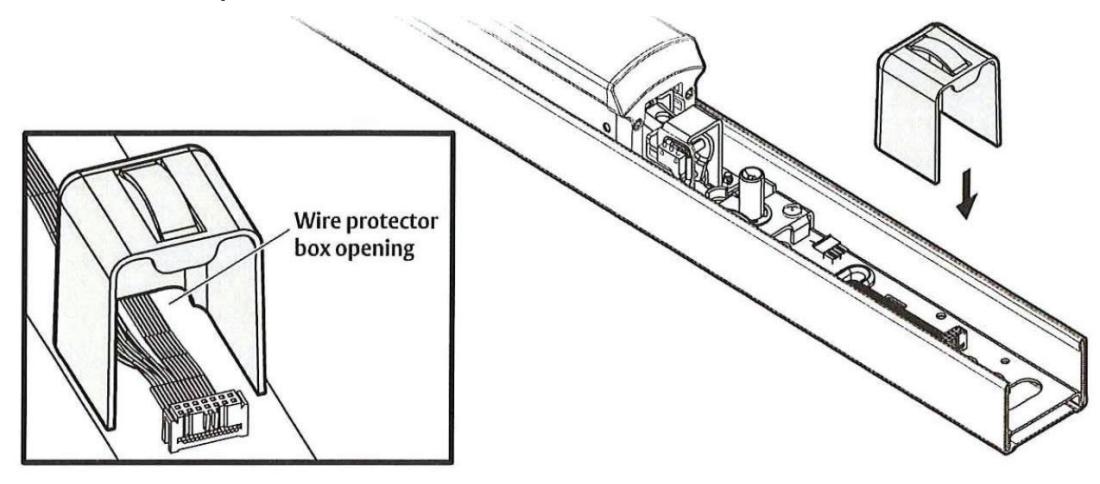
• Install the wire protector box into the device to prevent wire damage from the movement of the dogging assembly and end cover. All wires must move through the box opening.

• Hold the wire protector box in place when installing the end cover onto the cover assembly.
Installation Instructions

4 Retrofi tting to the MELR, continued
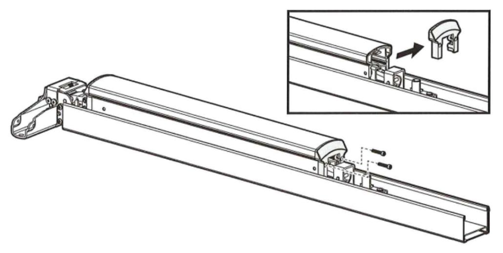
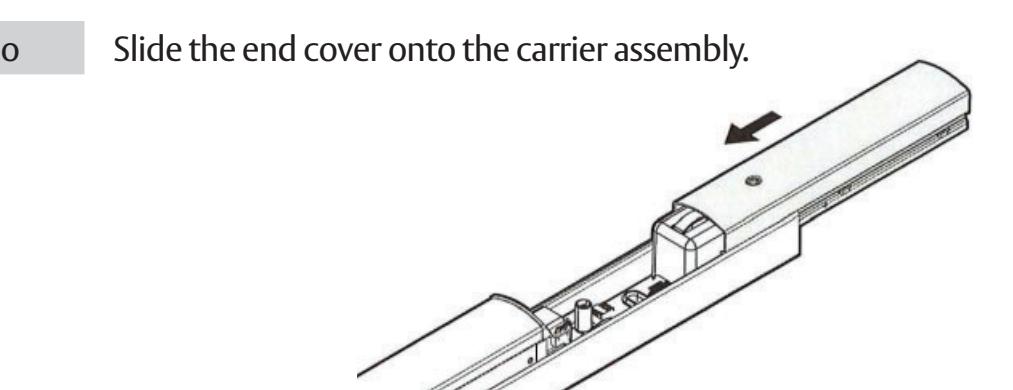
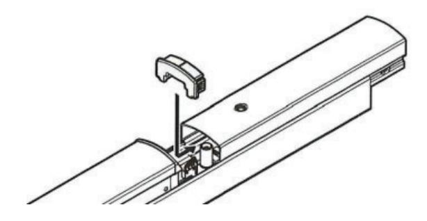
p Install the end cover.
- Push the cover onto the carrier assembly, leaving enough room to install the end cap.
- Once the end cap is installed, slide the cover until the end of the cover is flush with the end of the carrier assembly.
q Connect the wire harness to the controller.
For Mechanical or M94 with M93:
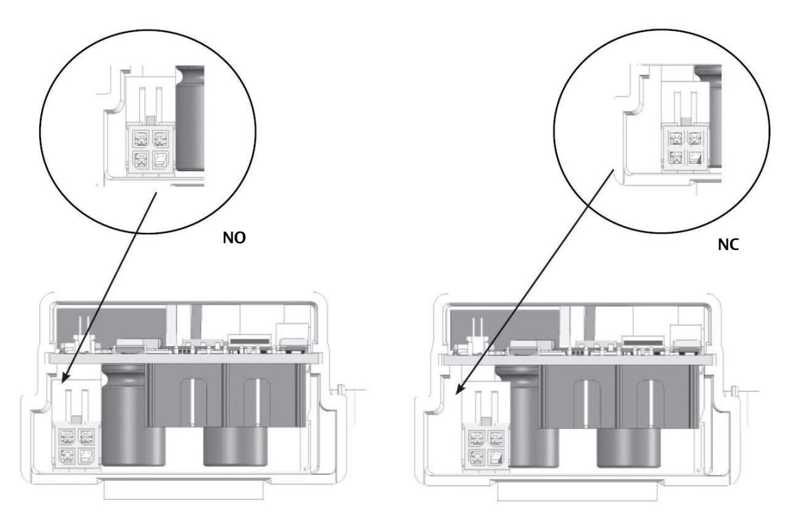
- Connect the motor wire harness and the trim monitor wire harness to the controller.
- Confirm the position of the trim monitor wire harness is set to "normally closed" (NC) or "normally open" (NO) as appropriate for the application. See Figure 8 on the next page.
13
Installation Instructions

4 Retrofi tting to the MELR, continued
r Connect the harness to the controller, continued
Figure 8 Normally Closed (NC) and Normally Open (NO) Trim Monitor Positions
s Install the controller into the carrier assembly
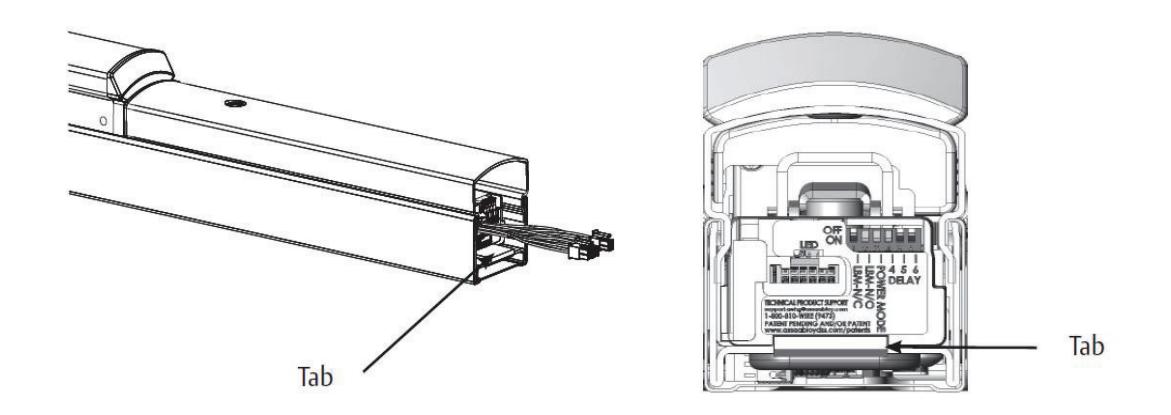
• Slide controller into touch bar, making sure tab is securely attached over end of the carrier.
t Install the carrier assembly on the door using the saved mounting hardware.
MELR Retrofi t Upgrade
Installation Instructions

15

Corbin Russwin 225 Episcopal Road Berlin, CT 06037 USA Phone: 800-543-3658