Installation Instructions
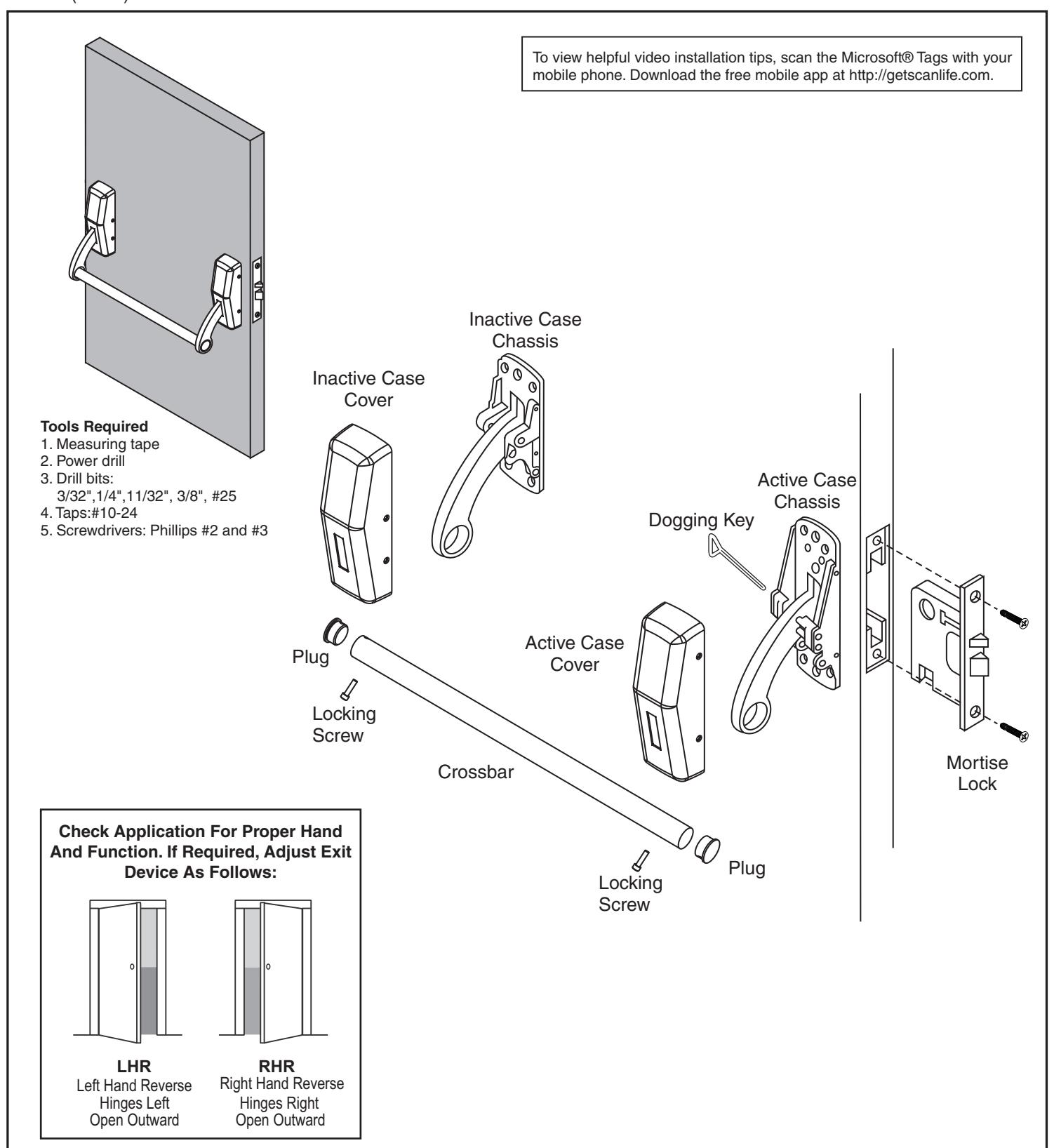
ED3600 & ED3600A Series Mortise Exit Device
ASSA ABLOY In Canada:
ASSA ABLOY Door Security Solutions Canada 160 Four Valley Drive
Vaughan, Ontario, Canada L4K4T9 www.assaabloy.ca
Technical Product Support: Phone: 888-607-5703
In U.S.:
Corbin Russwin, Inc.
225 Episcopal Road Berlin, CT 06037 USA
www.corbinrusswin.com
FM363 (05/15)


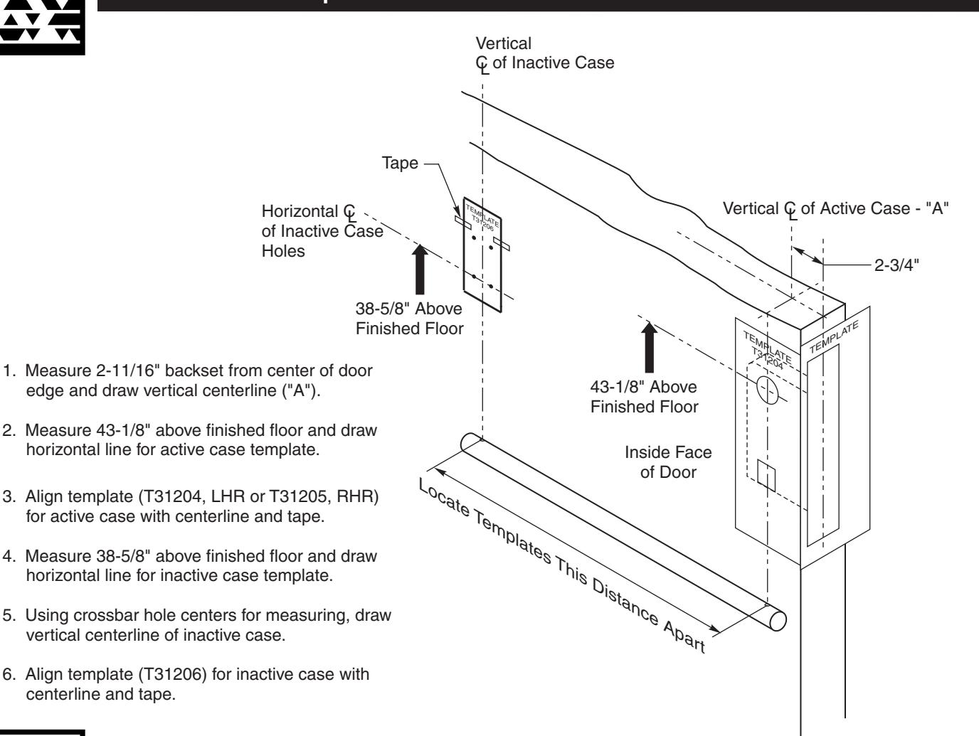
A. Active Case Template

B. Mortise Lock
- 1. Slide lockbody into mortise pocket of door.
- 2. Fasten mortise lock in place.
centerline and tape.
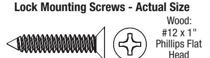
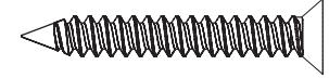
Lock Mounting Screws - Actual Size
Metal: #12-24 x 1/2" Phillips Flat Under Cut (Total 2)
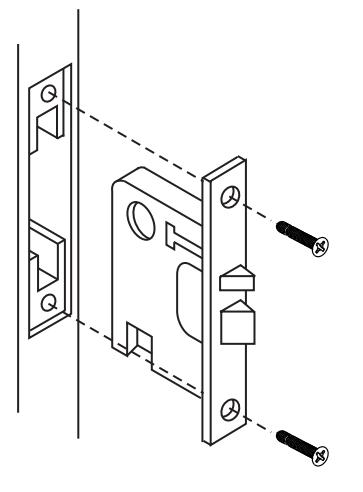
(Total 2)


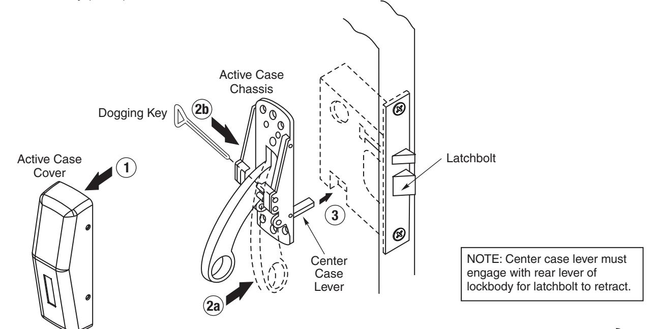
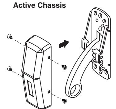
C. Active Case
- 1. Remove cover from active case chassis.
- 2. Depress arm and tighten with dogging key (provided) until held in down position (See 2a-2b).
- Position active case chassis against door so that the center case lever rests underneath the bottom of the mortise lockbody (See 3).
- 4. Lift active case chassis upward until the latchbolt is completely retracted.
- 5. With chassis in this position, mark hole locations for the top of the chassis.
- 6. Remove chassis from door then drill and tap top holes.
- 7. Undog arm by loosening with dogging key (provided), until arm rotates freely.
- 8. Align chassis with holes on door.
- 9. Screw in top two holes of active case chassis and mount to door.
- 10. Mark bottom hole locations on active case chassis.
- 11. Remove chassis from door.
- 12. Drill and tap bottom holes.
- 13. Position chassis on door and screw in top and bottom holes.
- 14. Verify latchbolt arm retracts.
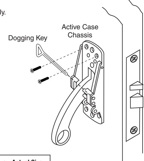
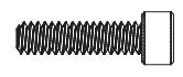
Active Case Mounting Screws - Actual Size

Wood: #10 x 1-1/4" Phillips Flat Head (Total 4)
Active Case Mounting Screws - Actual Size

Metal: #10-24 x 3/4" Phillips Flat Under Cut (Total 4)


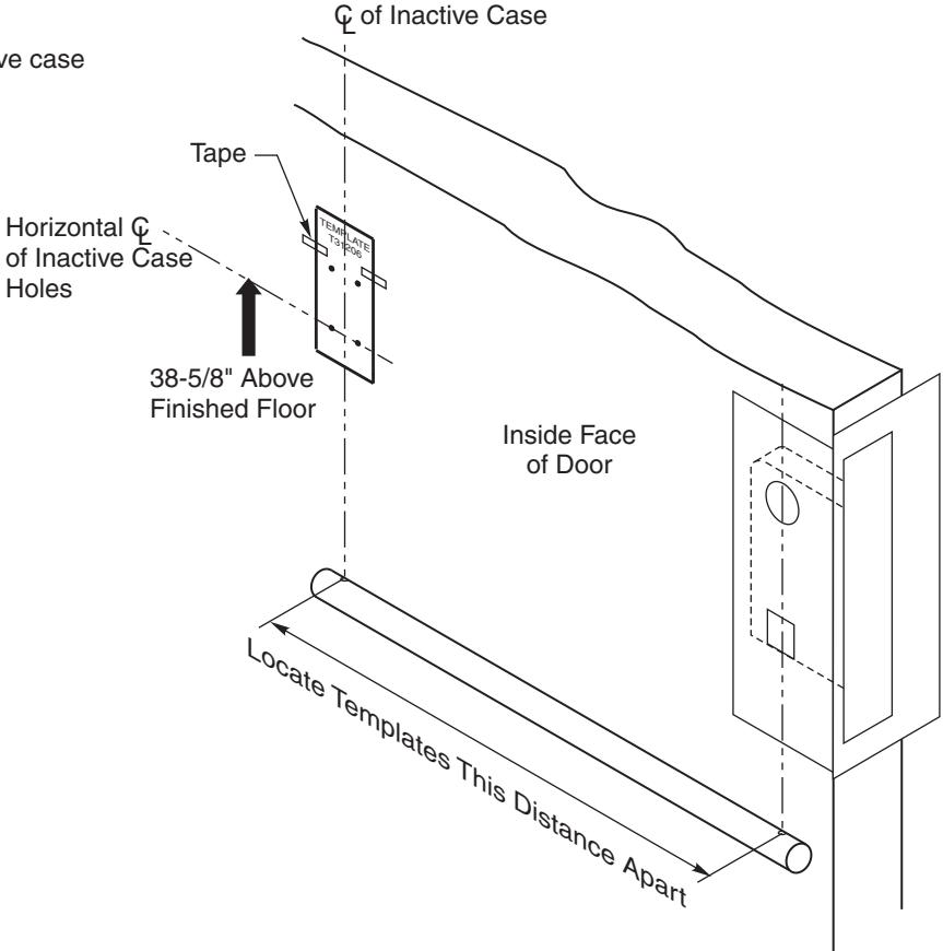
D. Inactive Case Template
- 1. Center punch mounting holes for inactive case on door.
- 2. Drill and tap holes in door.
Vertical

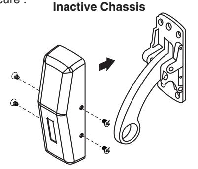
E. Inactive Case
- 1. Remove cover.
- 2. Mount chassis to door.
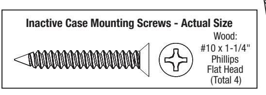
Inactive Case Mounting Screws - Actual Size

Metal: #10-24 x 3/4" Phillips Flat Under Cut (Total 4)
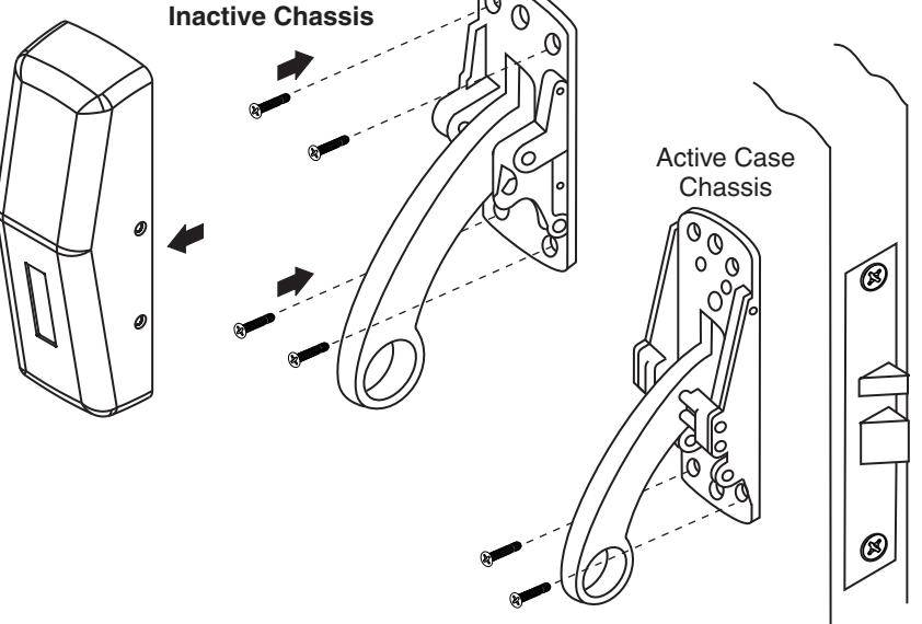


F. Attach Outside Trim
- 1. Slide thrubolt screws thru inside chassis and door.
- 2. Install cylinder (if applicable).
- 3. Align outside trim with exposed thrubolt screws and
- 4. Tighten cylinder set screw (if applicable).
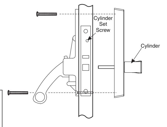


1/4 -20 x 2-3/8" Phillips Flat Head (Total 2)

G. Covers
1. Attach covers to both chassis and secure.
Cover Mounting Screws - Actual Size


#8-32 x 7/32" Phillips Oval Head (Total 8)

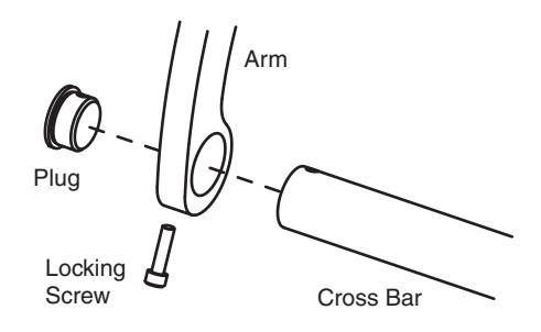
H. Crossbar
- 1. Slide crossbar into active chassis arm.
- 2. Slide crossbar into inactive chassis arm.
- 3. Insert plugs and secure to bar with locking screws.
- 4. Depress the crossbar to confirm the latchbolt retracts.
Crossbar Mounting Screws - Actual Size

#10-24 x 3/4" Socket Head Cap Screw (Total 2)