


Installation Instructions ML20900 Series Electrified Mortise Lockset

FM357 10/18
In U.S.: Corbin Russwin, Inc. 225 Episcopal Road Berlin, CT 06037 USA www.corbinrusswin.com
In Canada: ASSA ABLOY Door Security Solutions Canada 160 Four Valley Drive Vaughan, Ontario, Canada L4K4T9 www.assaabloy.ca
Attention Installer
Please read these instructions carefully to prevent missing important steps.
Please Note: Improper installations may result in damage to the lock and void the factory warranty.
Important: The accuracy of the door preparation is critical for proper functioning and security of this lock. Misalignment can cause premature wear and a lessening of security.
WARNING
This product can expose you to lead which is known to the state of California to cause cancer and birth defects or other reproductive harm. For more information go to www.P65warnings.ca.gov.
08/2018
For Technical Assistance call Corbin Russwin at 1-800-810-WIRE (9473)

Table of Contents
| 1) Warning2 | |
|---|---|
| 2) General Description3 | |
| 3) Specifications / Features 3 | |
| 4) Product Illustration 4 | |
| 5) Installation Instructions 5 | |
| 6) Wiring Diagrams14 | |
| 7) Mechanical Operational Check 16 | |
| 8) Electrical Operational Check16 |
1) Warning
Warning: Changes or modifications to this unit not expressly approved by the party responsible for compliance could void the user's authority to operate the equipment.
This device complies with Part 15 of the FCC Rules. Operation is subject to the following two conditions: (1) this device may not cause harmful interference, and (2) this device must accept any interference received, including interference that may cause undesired operation.
Note: This equipment has been tested and found to comply with the limits for a Class B digital device, pursuant to Part 15 of the FCC Rules. These limits are designed to provide reasonable protection against harmful interference in a residential installation.
This equipment generates, uses and can radiate radio frequency energy and if not installed and used in accordance with the instructions, may cause harmful interference to radio communications. However, there is no guarantee that the interference will not occur in a particular installation. If this equipment does cause harmful interference to radio or television reception, which can be determined by turning the equipment off and on, the user is encouraged to try to correct the interference by one or more of the following measures:
- Reorient or relocate the receiving antenna
- Increase the separation between the equipment and receiver
- Connect the equipment into an outlet on a circuit different from that to which the receiver is connected
- Consult the dealer or an experienced TV technician for help
This Class B digital apparatus complies with Canadian ICES-003.
Cet appareil numérique de la classe B est conforme avec la norme NMB-003 du Canada.

Observe precautions for handling electrostatic sensitive devices. !
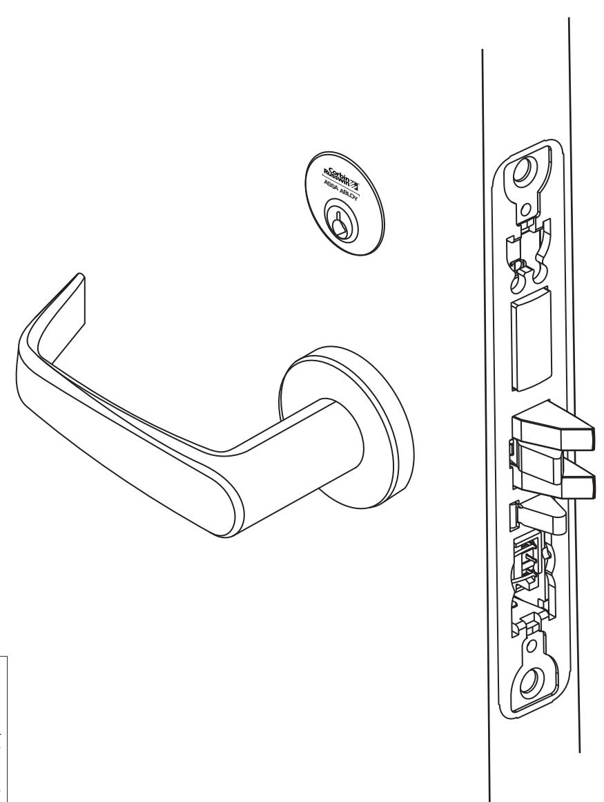
ML20900 ECL Series Mortise Lock

2) General Description
Combine simplicity and access control with the Corbin Russwin ML20900 ECL series electrically controlled mortise lock. Utilizing the proven ML2000 Series mortise lockset with the patented quick reversible latchbolt, the ML20900 series provides electrified remote locking and unlocking.
3) Specifications / Features
- Latch Stainless steel, 3⁄4" projection
- Deadbolt Stainless steel, 1" projection
- Guardbolt Stainless steel, non-handed
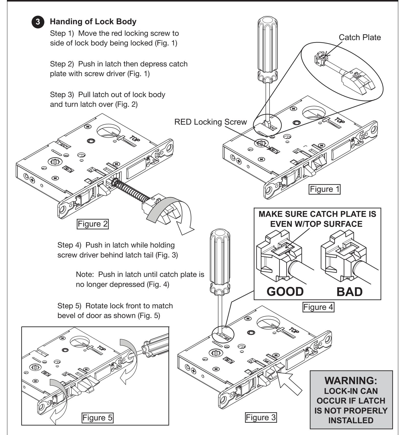
- Handed Easily field reversible without opening case
- Case 12 gauge heavy duty wrought steel
- Fail safe or fail secure operation (can be specified when ordering or easily field configured)
- Operates from 12-24V
- UL and CUL listed for use on Fire Doors
- Wire from EAC panel to door must be shielded with a drain terminated at EAC panel controller
BPS Supply
Electrical Specifications 12/24VDC System
- Reader draw = .140 Amp
- Actuator draw = .015 Amp continuous
- Maximum 2 locks per 1 Amp power supply (1/2 Amp peak current draw)

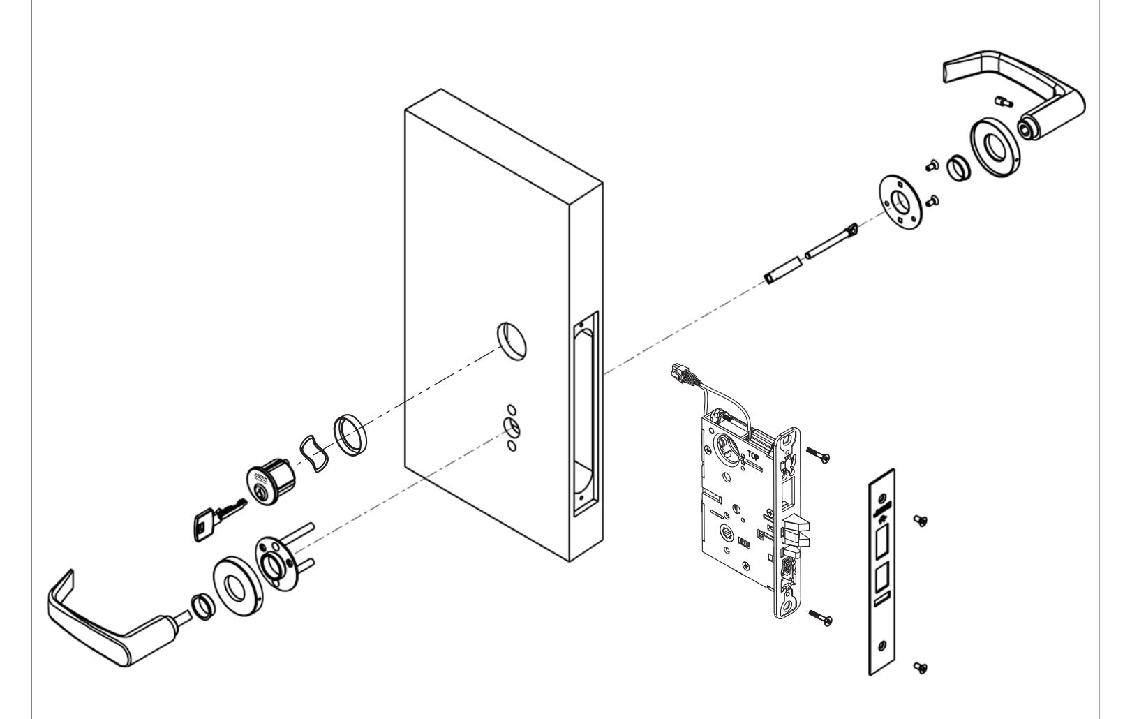
4) Product Illustration
Tools Required:
- Phillips Screw Driver (Standard size)
- Flat Blade Screw Driver (Standard size)
- 1/8" Allen Wrench

5) Installation Instructions
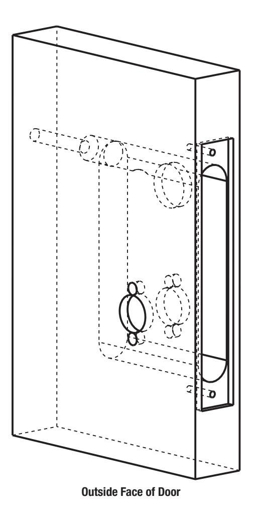
1. Verify Hand and Bevel of door. Illustrations shown are as viewed from the outside or secure side of opening.
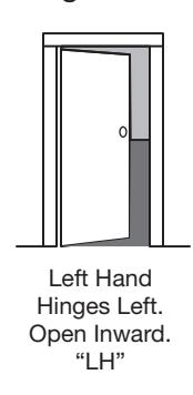
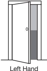
Left Hand Reverse Bevel Hinges Left. Open Outward "LHRB"
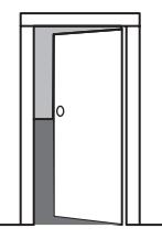
Right Hand Hinges Right. Open Inward. "RH"
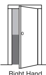
Right Hand Reverse Bevel Hinges Right. Open Outward "RHRB"
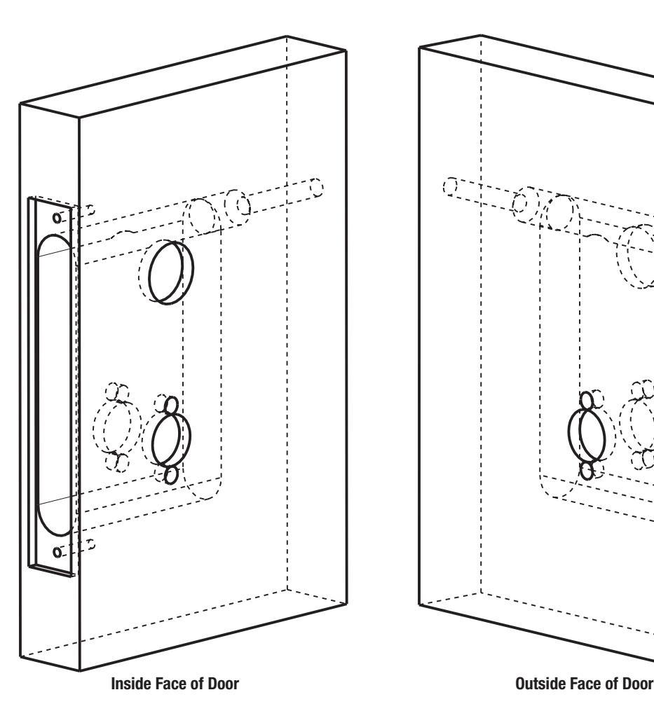
2. Prep door according to supplied door marker. For door manufacturer templates, visit www.corbinrusswin.com.


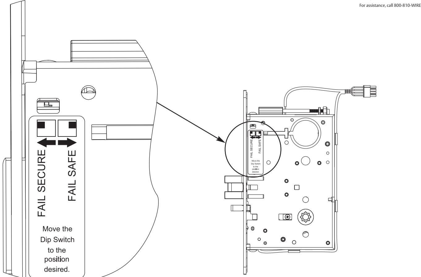
4. Configuring the Fail Safe/Fail Secure DIP switch settings: Please note that the lock must be cycled once in order to change the fail safe/fail secure setting.
Check polarity: Verify + (red) wire
-
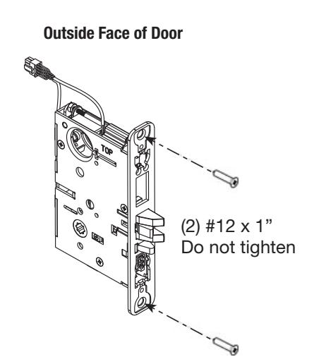
5. Install Lock Body into Door:
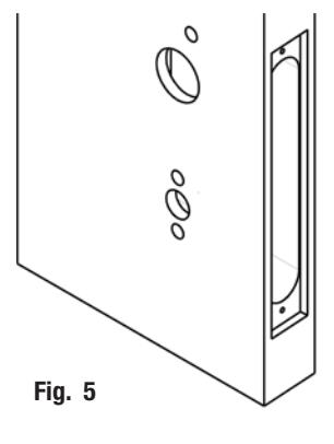
- a. Plug mortise lock harness into ® ElectroLynx harness in door (Fig. 5). Important: Door must remain open during installation. Use door stop.
- b. Install, but do not tighten two #12 x 1" combination screws through lock body (Fig. 5).

6. Install Cylinder:
-
a. Thread cylinder into lock body (Fig. 6a).
- Note: Make sure cylinder is oriented correctly (Fig. 6a1).
- b. Tighten cylinder clamp using 7/64" allen wrench (provided) (Fig. 6b).
- c. Turn the key to make sure that lock functions correctly (latch, deadbolt, and key).
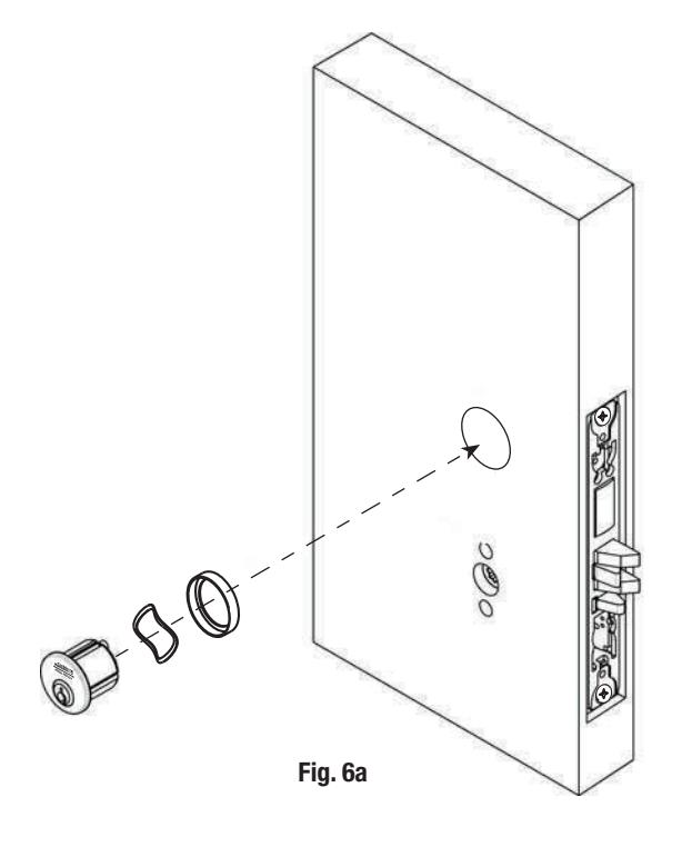
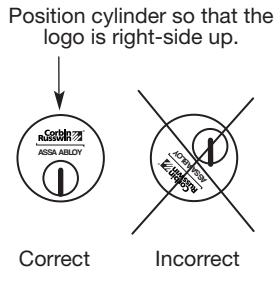
Fig. 6a1


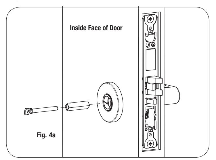
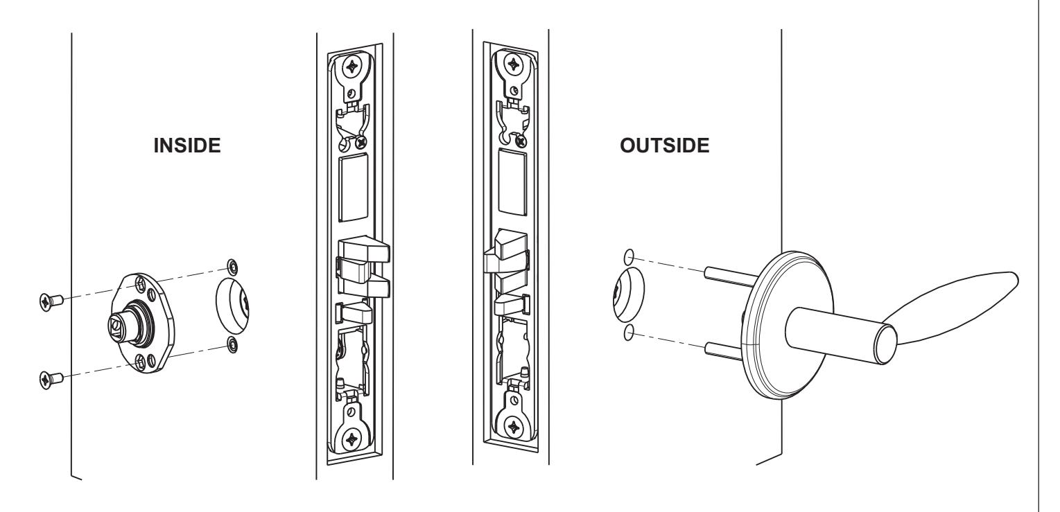
5) Installation Instructions (Continued) Inside Face of Door
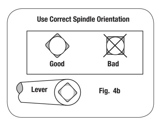
7a. Install Standard Lever Trim. Refer to 7b on following pages for Trim:

ML20900 ECL Series Mortise Lock

ASSA ABLOY
5) Installation Instructions (Continued)
Step 4
Step 5
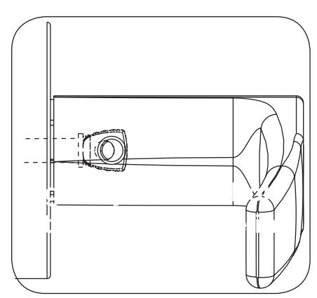
Adjustment bolt needs to be threaded in farther.
Align adjustment bolt with threaded hole in lever
Adjustment bolt needs to be unthreaded.
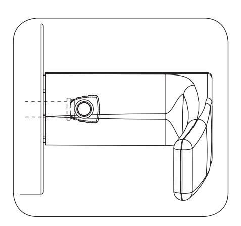
Adjustment bolt fully aligned.
Step 6
Notes:
- Unthread Adjustment Bolt approximately four turns for a good starting point (After being fully tightened)
- Make sure O/S lever is fully inserted into adapter plate before aligning adjustment bolt.
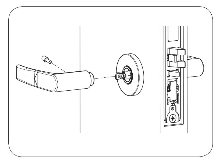

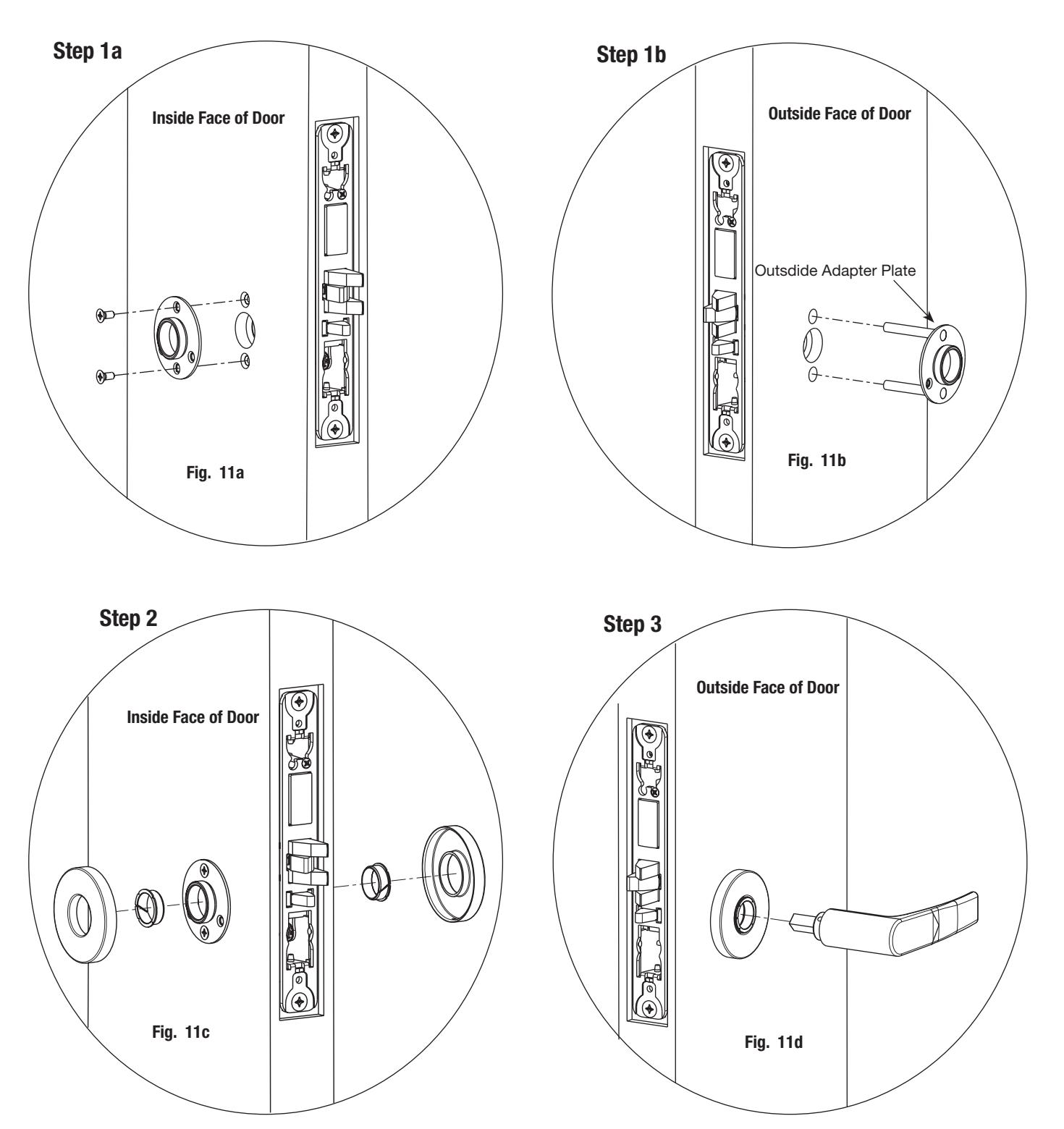
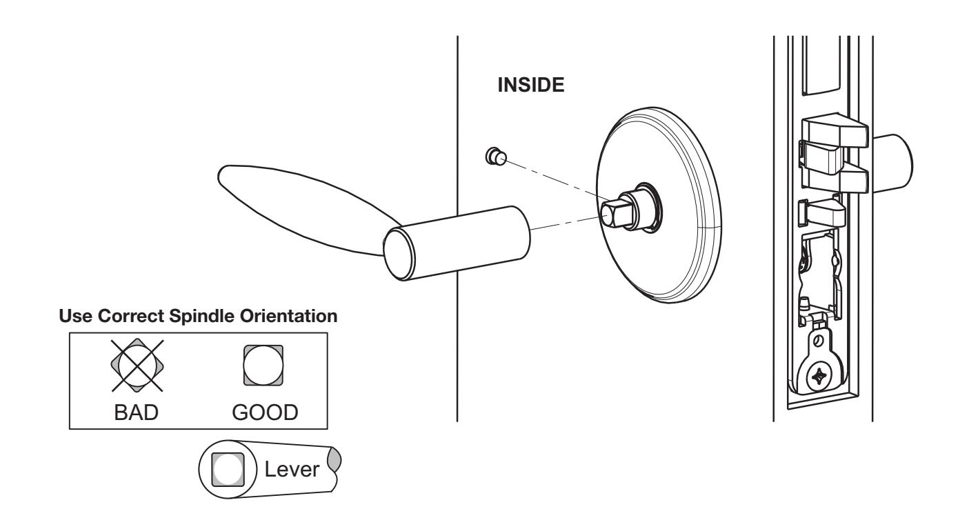
7b. Install Trim:
1.)
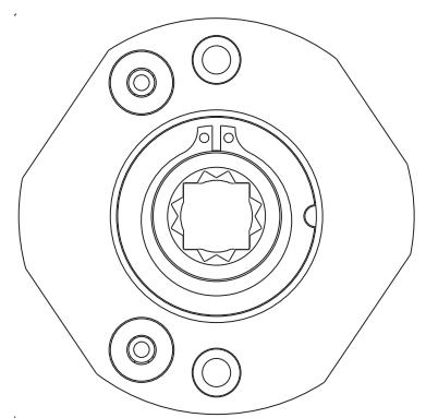
Thread adapter plate hub into lever and fully tighten NOTE: Spindle can be used to help thread hub into lever Adapter Plate Hub
Align adapter plate hub with square hole in lever; keeping hub as tight as possible
2.)

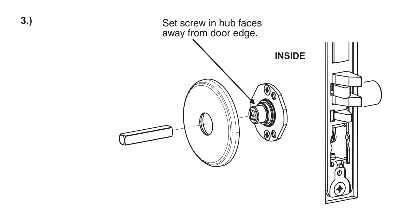
4.)

-
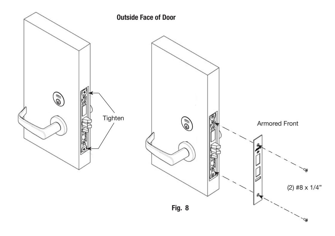
8. Install Armored Front:
- a. Tighten (2) screws through lock body.
- b. Attach armored front with two #8 x ¼" screws (Fig. 8).

6) Wiring Diagrams
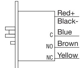
Lock Schematics

(Request to Exit) Red+ Black- AC/DC NŎ
For assistance, call 800-810-WIRE

Power Leads
Power Leads x M105 (Security Monitor)
Power Leads x M92
Red+
Black- AC/DC
White Green \M92 Orange

Monitoring Options:
M91 - Latchbolt Monitor
Latchbolt monitoring is a SPDT switch which monitors the full extension of the main latch. Activated when latch is fully projected.
M92 -Request to Exit Monitor
Request to Exit monitoring is a SPDT switch which monitors the activation of the trim. (Both levers activate switch.) Activated when unlocked lever is rotated. Rotating locked lever will not activate switch.
M105 -Security Monitor
Security Monitor is two switches in series that monitors lock status (locked or unlocked) and Auxiliary Latch position. Activated when door is closed and locked.
M91 x M92 - Latchbolt and Request-to-Exit Monitoring
M92 x M105 - Request-to-Exit and Security Monitoring

ASSA ABLOY
6) Wiring Diagrams

Operation:
Free egress at all times. Door is locked at all times preventing entry from the stairwell to a floor. Fire alarm activation will allow re-entry from the stairwell to the floor. Power failure will allow re-entry from the stairwell to the floor.
Controlled Entry With Alarm

Operation:
Free egress at all times. User exits through the door which triggers the M92 switch which shunts the alarm. Door is locked at all times preventing unauthorized entry. Authorized entry is permitted by presenting a valid user card. Forced entry will trigger M91 switch and activate alarm. Alarm is deactivated by a valid user card.
Tower Stairwell Access Control on Employee Entrance

Operation:
Free egress at all times. Door is locked at all times preventing unauthorized entry. Authorized entry is permitted by presenting a valid user card.

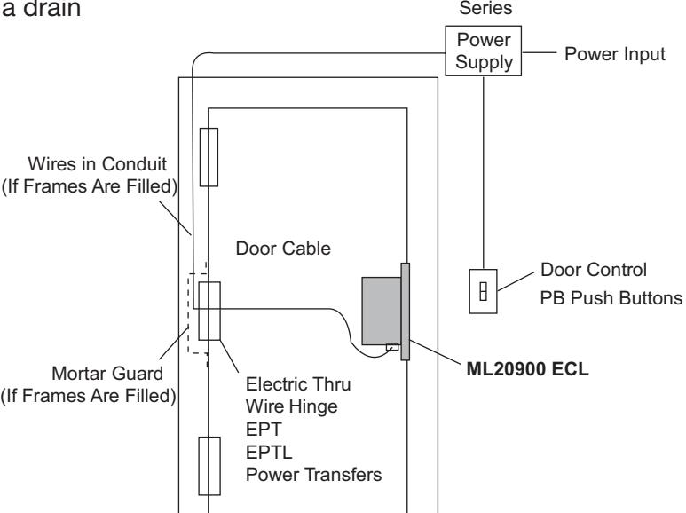
® ElectroLynx a system of universal Molex plug-in connectors and ® standardized color-coded wiring, makes installing electrified doorway components a snap!
Consult factory for electrical system layouts, riser and wiring diagrams.
ML20900 ECL Series Mortise Lock

7) Mechanical Operational Check
For mortise locks with cylinders:
- a. Insert key into cylinder and rotate: There should be no friction against lock case, wire harness or any other obstructions.
- b. The key will retract the latch: Key should rotate freely.
- c. Inside lever: Ensure it retracts the latch.
- d. Close door: Ensure latch fully extends and does not bind.
8) Electrical Operational Check
Lock/UnLock Check:
- a. Turn power ON.
- b. Send unlock signal from control panel.
- c. Verify lock unlocks and re-locks at desired intervals.
Switch Signal Check:
d. Monitor switch signals at control panel and verify each switch activates correctly based on chosen wiring configuration (NO/NC).
EAC Card Reader Check:
e. Refer to Card reader instructions.