


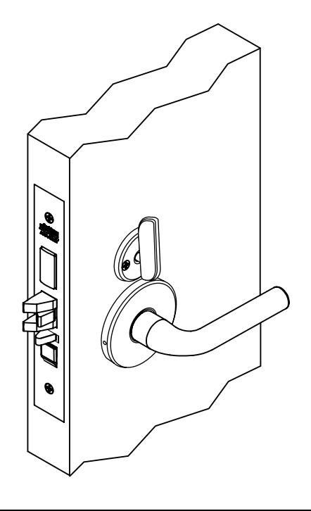
Sectional Trim
ML2000 Series Mortise Locks
For Museo® Series Designer Trim, refer to installation instructions FM601.

WARNING
This product can expose you to lead which is known to the state of California to cause cancer and birth defects or other reproductive harm. For more information go to www.P65warnings.ca.gov.
| TOC | Table of Contents | |
|---|---|---|
| 1 | Mortise Lock Handing Instructions 2 | |
| 2 | Sectional Trim Installation 3 | |
| 3 | Half Active Sectional Trim Installation 5 | |
| 4 | Full Dummy Sectional Trim Installation 7 | |
| 5 | Half Dummy Sectional Trim Installation 8 | |
| 6 | Installing Knobs Sold Before October 2017 ONLY: 8 |
For installation assistance contact Corbin Russwin 1-800-543-3658 • techsupport.corbinrusswin@assaabloy.com
FM475 11/18
Figure 2
1 Mortise Lock Handing Instructions
- 1. Move red locking screw to side of lockbody being locked.
- 2. Push in latch. Depress catch plate with screwdriver. (Figure 1)
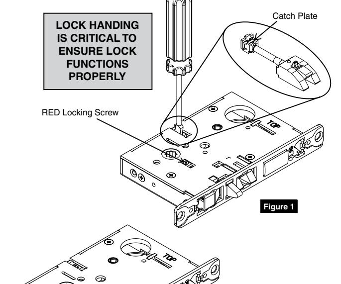
- 3. Pull latch out of lock-body and turn latch over. (Figure 2)
- 4. Push in latch while holding screwdriver behind latch tail. (Figure 3)
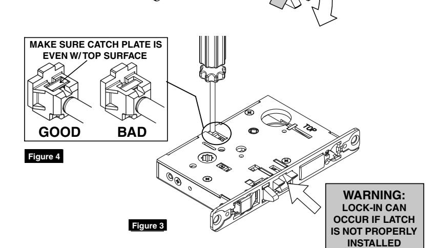
NOTE:
Push in latch until catch plate is no longer depressed. (Figure 4)
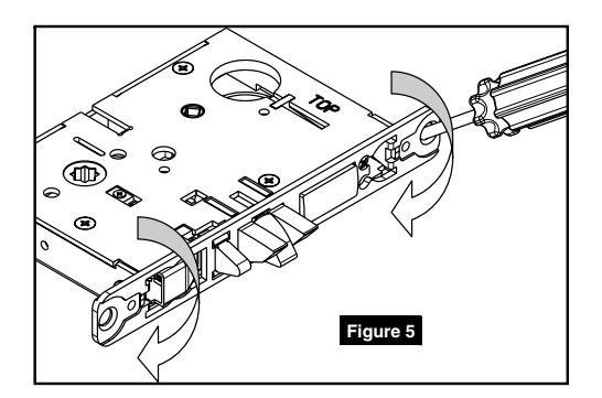
5. Rotate lock front to match bevel of door, as shown. (Figure 5)
ML2000 Series Mortise Lock
Installation Instructions

2 Sectional Trim Installation
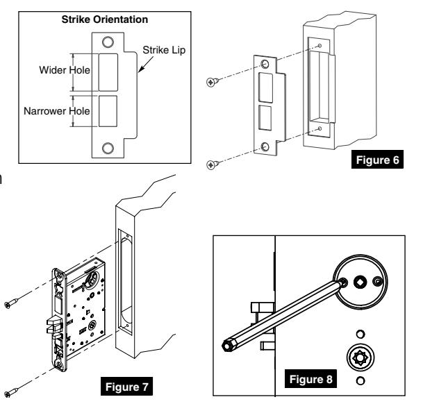
1. Install strike using shorter 3/4" strike mounting screws. If strike box is needed, insert between strike and door frame. (Figure 6)
2. Insert mortise lock into door and hand tighten longer 1" mounting screws. (Figure 7)
NOTE:
Make sure lock is unlocked. If lock has a toggle, push bottom of toggle inward to unlock during installation.
- 3. Mark turn-piece or emergency key mounting holes. (Figure 8) Remove lock and drill two (2) .110" (BIT #35) holes where marked.
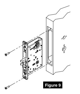
- 4. Reinstall lock following Step 2. (Figure 9)
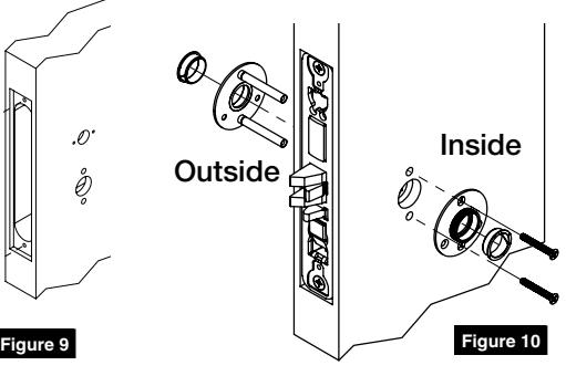
- 5. Install outside and inside adapter plates. (Figure 10)
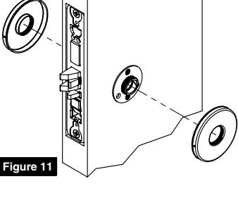
- 6. Screw roses onto adapter plates. (Figure 11)
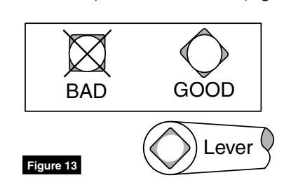
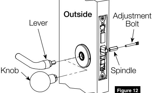
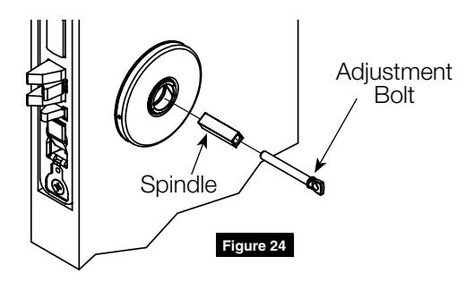
- 7. Install outside lever or knob by inserting adjusment bolt on oposite side of door. Tighten bolt finger-tight and then loosen a few turns. (Figure 12)
NOTE:
Use correct spindle orientation. (Figure 13)
2 Sectional Trim Installation, (cont.)
8. Install inside lever or knob by inserting dowel screw. (Figure 14)
NOTE:
Make sure adjustment bolt hole is aligned with lever or knob hole. (Figure 15)
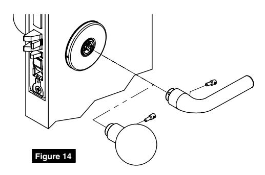
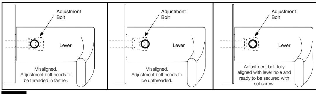
Figure 15
9. Install cylinder with wave spring and collar. Secure with cylinder set screw. (Figure 16)
NOTE:
- Pull key slightly out of cylinder to help thread into lockbody.
- Cylinder must be oriented correctly. (Figure 17)
- 10. Tighten lock mounting screws.
- 11. Mount turn-piece or emergency key. (Figure 18)
NOTE:
Turn-piece should be oriented vertically with holes in base plate aligned with mounting holes in door.
Figure 18 Turn-Piece Figure 19 Lock Mounting Screws
Figure 16 Figure 17
12. Install armored front. (Figure 19)
For installation assistance contact Corbin Russwin 1-800-543-3658 • techsupport.corbinrusswin@assaabloy.com
4 FM475 11/18
Key and cylinder must be rotated as shown.
Correct Incorrect
ASSAABLOY
ASSA ABLOY
3 Half Active Sectional Trim Installation
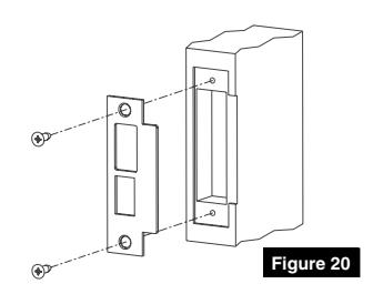
1. Install strike using shorter 3/4" strike mounting screws. If strike box is needed, insert between strike and door frame. (Figure 20)
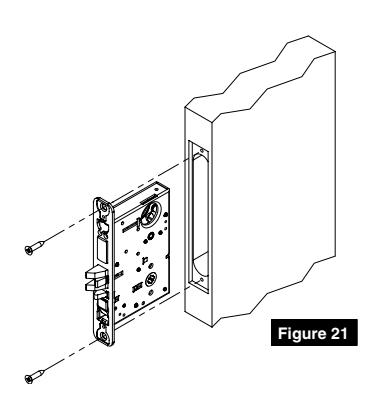
2. Insert mortise lock into door and hand tighten longer 1" mounting screws. (Figure 21)
NOTE:
Make sure lock is unlocked. If lock has a toggle, push bottom of toggle inward to unlock during installation.
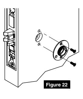
- 3. Install inside adapter plate. (Figure 22)
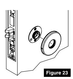
- 4. Screw on rose. (Figure 23)

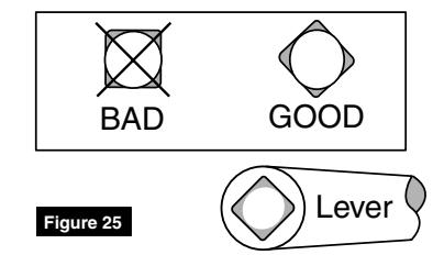
NOTE:
Use Correct Spindle Orientation Use correct spindle orientation. (Figure 25)

3 Half Active Sectional Trim Installation, (cont.)
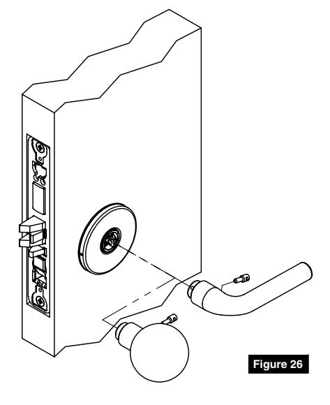
6. Install inside lever or knob by inserting dowel screw. (Figure 26)
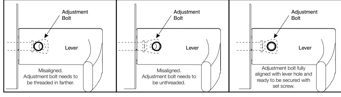
NOTE:
Make sure adjustment bolt hole is aligned with lever or knob hole. (Figure 27)
- Figure 27
- 7. Tighten lock mounting screws.
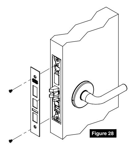
- 8. Install armored front. (Figure 28)
the express written permission of ASSA ABLOY Access and Egress Hardware Group, Inc. is prohibited.
Corbin Russwin is a brand associated with ASSA ABLOY Access and Egress Hardware Group, Inc., an ASSA ABLOY Group company. Copyright © 2018, ASSA ABLOY Access and Egress Hardware Group, Inc. All rights reserved. Reproduction in whole or in part without

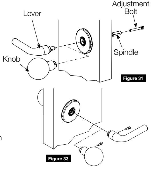
4 Full Dummy Sectional Trim Installation
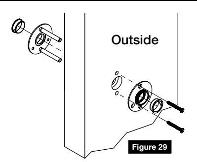
1. Install outside and inside adapter plates. (Figure 29)
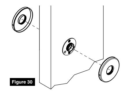
- 2. Screw roses onto adapter plates. (Figure 30)
- 3. Install outside lever or knob by inserting adjustment bolt on opposite side of door. Tighten bolt finger-tight then loosen a few turns. (Figure 31)

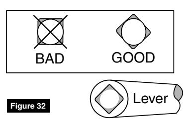
Use Correct Spindle Orientation Use correct spindle orientation. (Figure 32)

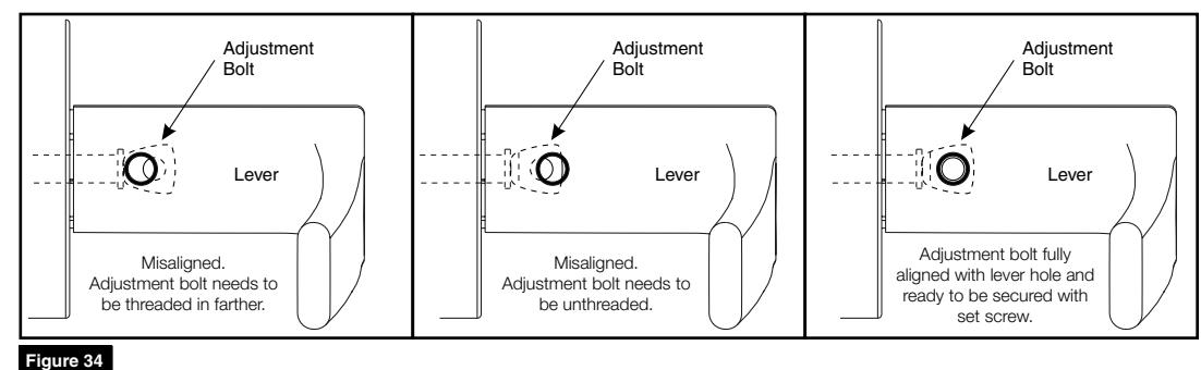
NOTE:
Make sure adjustment bolt hole is aligned with lever or knob hole. (Figure 34)

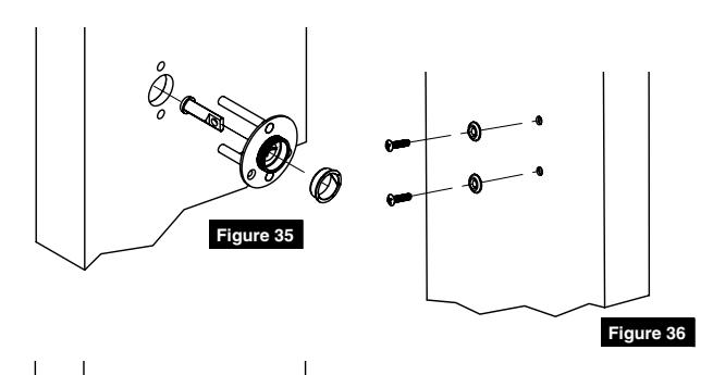
5 Half Dummy Sectional Trim Installation
- 1. Assemble and Install outside dummy adapter plate. (Figure 35)
- 2. Install mounting screws and washers. (Figure 36)
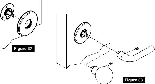
- 3. Screw on rose. (Figure 37)
- 4. Install inside lever or knob by inserting dowel screw. (Figure 38) Figure 37
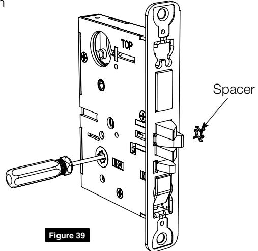
6 Installing Knobs Sold Before October 2017 ONLY:
Before inserting knob lockbody into door, push spacer out of lock using a screwdriver. (Figure 39)
NOTE:
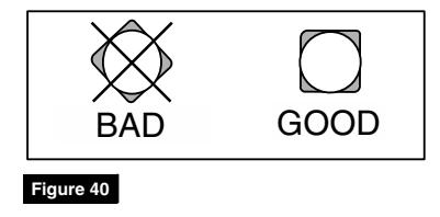
Install spindles in square orientation. (Figure 40)
Corbin Russwin 225 Episcopal Road Berlin, CT 06037 Phone: 800-543-3658 Fax: 800-447-6714 corbinrusswin.com