


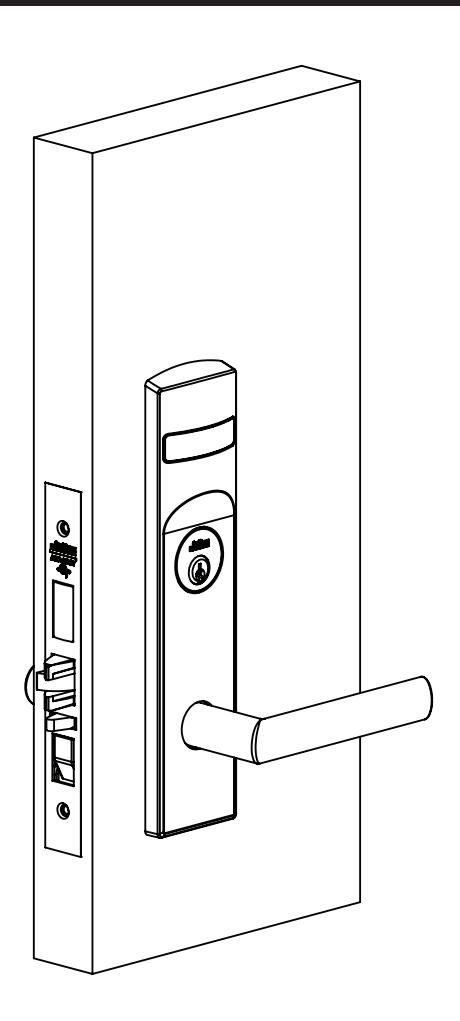
Installation Instructions

ML2000 Series Mortise Lock
Used with VN Escutcheon Trim and V Series Indicators

This product can expose you to lead which is known to the state of California to cause cancer and birth defects or other reproductive harm. For more information go to www.P65warnings.ca.gov.
Used with VN Escutcheon Trim and V Series Indicators
Installation Instructions
| TOC | Table of Contents | |
|---|---|---|
| 1 | Tools Required 3 | |
| 2 | Indicator Variants3 | |
| 3 | Mortise Lock Handing Instructions 4 | |
| 4 | Rehanding Indicator (if necessary) 5 | |
| 5 | Installation Instructions 6 | |
| a | Prepare Door 6 | |
| b | MUSÉO® LEVERS ONLY: Attach Levers to Escutcheons 6 | |
| c | Install Lock and Outside Trim 6 | |
| d | Install Cylinder 7 | |
| e | Install Inside Trim 7 | |
| f | STANDARD LEVERS ONLY: Attach Levers 8 | |
| g | Install Outside Front 9 | |
| h | Perform Functional Check 9 | |
| 6 | Indicator Parts | 10 |
Used with VN Escutcheon Trim and V Series Indicators
Installation Instructions

1 Tools Required
- Phillips screwdriver (#1, #2 and #3 sizes)
- Flat-blade screwdriver
- 1/8" Allen wrench standard trim
- 3/32" Muséo®
- 7/64" ML20900/ML20600 NAC
- 3/8" dia. drill bit
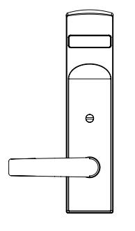
2 Indicator Variants
Depending on function and option ordered, indicators are provided in the following variations. These instructions detail how to install with cylinder, however other variations follow similar instructions. (Figure 1 )
Contact factory with any questions.
Thumbturn - For installation on inside of door.
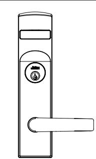
Cylinder – For installation on inside or outside of door.
Coin Turn – For installation on outside of door.
No input/blank - For installation on inside of door.
Figure 1
Used with VN Escutcheon Trim and V Series Indicators
Installation Instructions

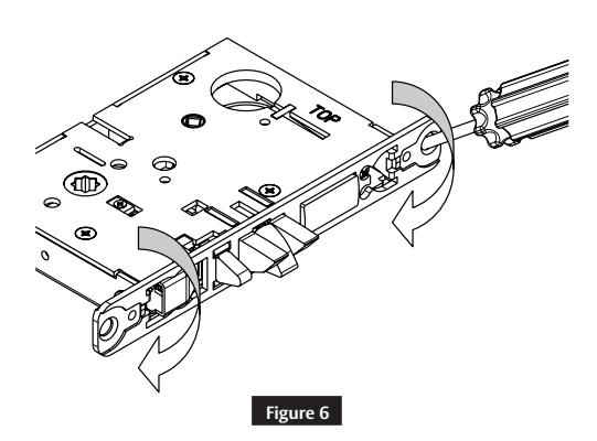
3 Mortise Lock Handing Instructions
- 1. Move red locking screw to side of lock body being locked.
- 2. Push in latch. Depress catch plate with screwdriver. ( Figure 2 )
- 3. Pull latch out of lock body and turn latch over. (Figure 3 )
4. Push in latch while holding screwdriver
behind latch tail. ( Figure 5 )
Figure 4
GOOD BAD
MAKE SURE CATCH PLATE IS EVEN WITH TOP SURFACE
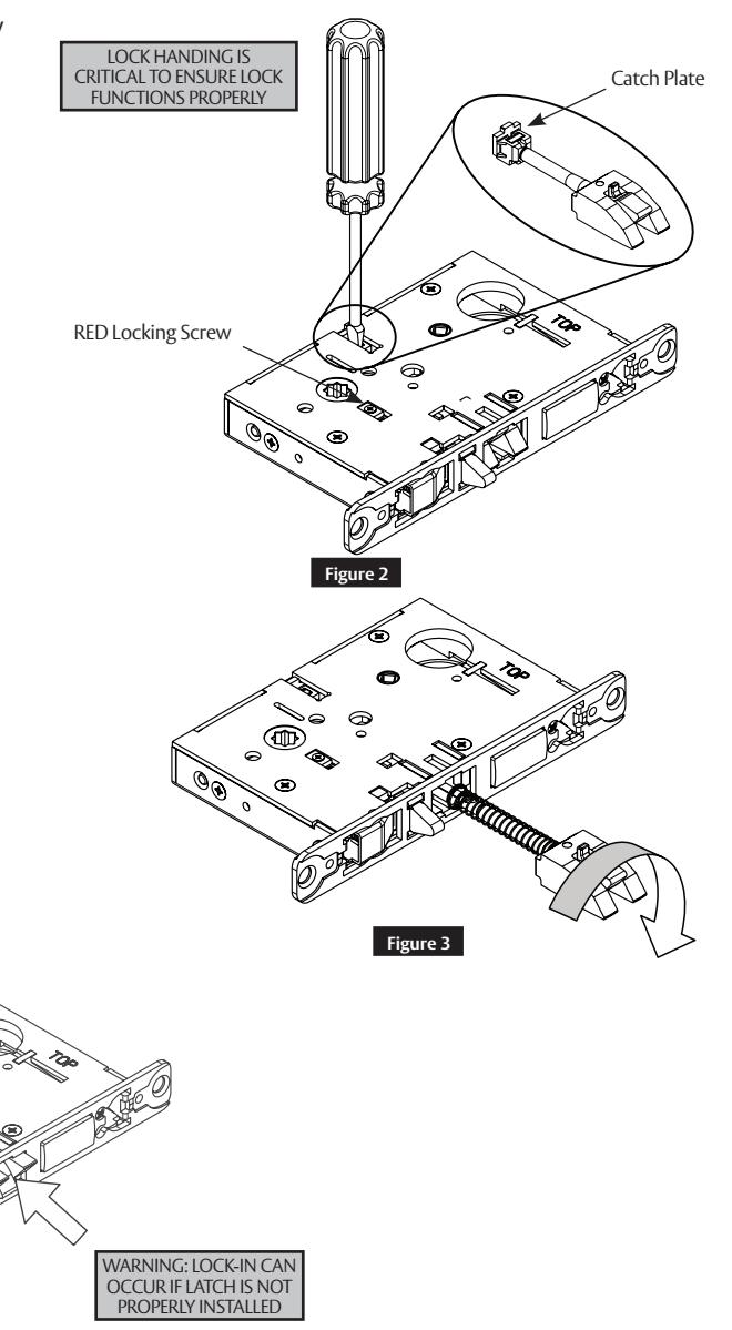
Note:
Ensure that latch is pushed in until catch plate is no longer depressed. (Figure 4)
Figure 5
5. Rotate lock front to match bevel of door as shown. (Figure 6 )
Used with VN Escutcheon Trim and V Series Indicators
Installation Instructions

4 Rehanding Indicator (if necessary)
1. Verify hand and bevel of door. ( Figure 7 )
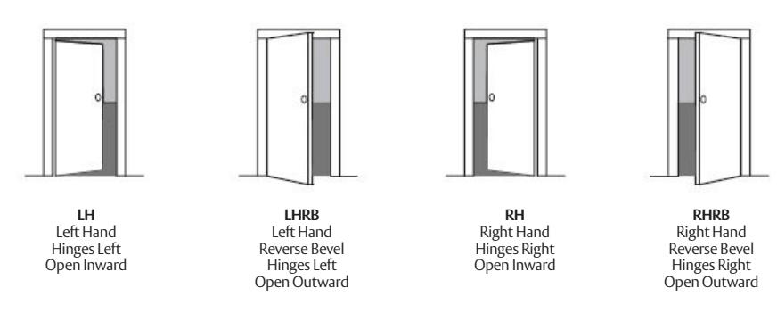
Figure 7
Note:
Stand on outside of locked door when determining door hand.
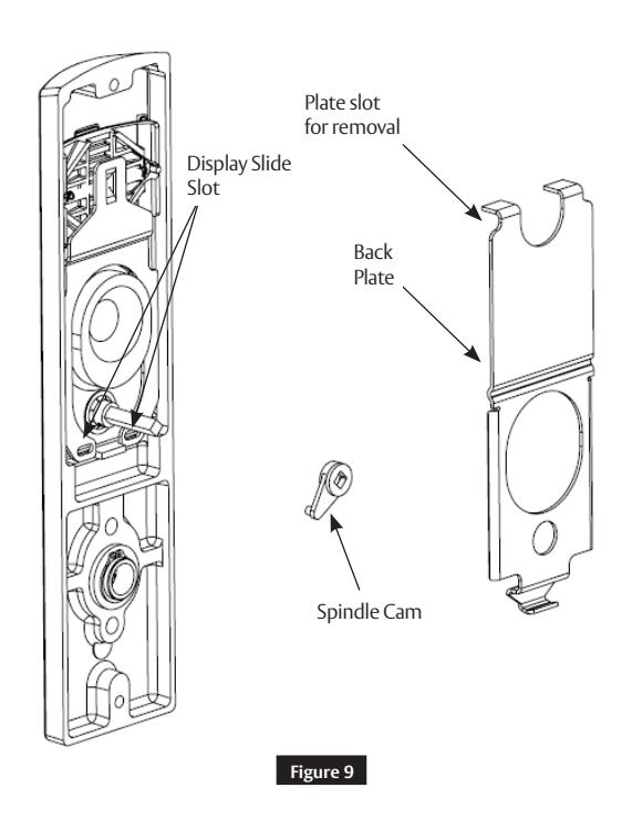
- 2. Remove indicator back plate by pulling out from top slot.
- 3. Remove spindle cam from assembly.
- 4. Position the spindle cam in the correct direction for door hand. ( Figure 8)
- 5. Slide spindle cam post into the correct slot of the display slide (Figure 9 ).
- 6. Press back plate back into original position.
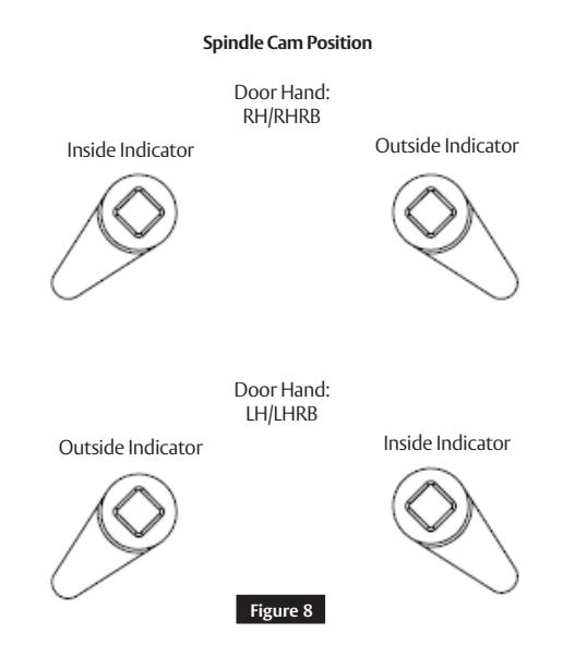
Note:
Verify handing on both outside and inside indicators.
Used with VN Escutcheon Trim and V Series Indicators
Installation Instructions

5 Installation Instructions
a Prepare Door
Prepare door for function holes, size, and location according to FM500 door marker template, if not already prepped.
b MUSÉO ® LEVERS ONLY: Attach Levers to Escutcheons
- 1. Thread lever onto adapter.
- 2. Insert spindle into adapter and fully tighten onto lever. Loosen smallest amount that allows spindle to engage lever.
- 3. Verify correct spindle orientation with the lever held horizontally. (Figure 10)
NOTE:
Use correct spindle orientation. ( Figure 10 )
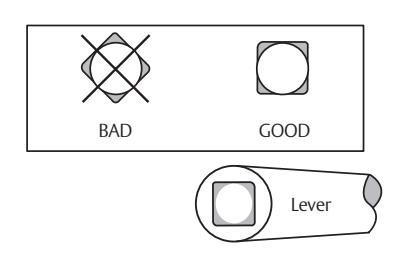
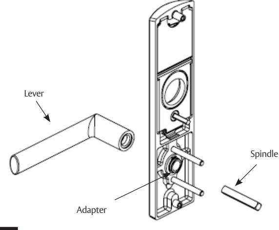
Figure 10
c Install Lock and Outside Trim
- 1. Verify strike location according to template. Clean out door pocket and door edge of debris.
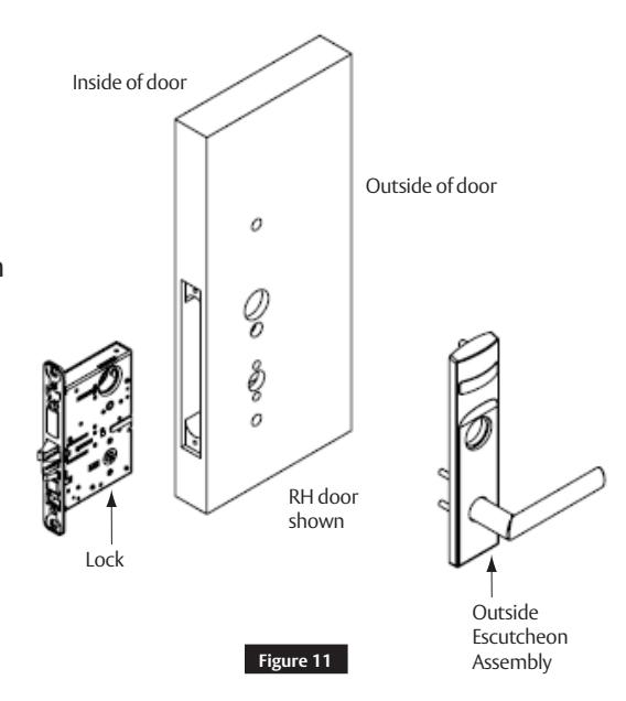
- 2. Make sure handing of the lock matches handing of door. Slide lock into the door and hold.
- 3. Slide outside lever and escutcheon assembly through door; lock body and hold. ( Figure 11)
- 4. Verify indicator is in unlocked position.
NOTE:
For installation assistance contact Corbin Russwin
- Keep door open while installing lock.
- Make sure lock is unlocked.
Used with VN Escutcheon Trim and V Series Indicators
Installation Instructions

5 Installation Instructions (cont.)
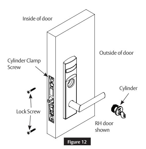
d Install Cylinder
- 1. Thread cylinder into lock until flush with surface.
- 2. Install the cylinder clamp screw (#2 Phillips screwdriver).
- 3. Check operation, and adjust cylinder if necessary.
- 4. Secure lock in door with two (2) Combination screws Do NOT tighten completely at this time. (Figure 12)
NOTE:
- CORBIN RUSSWIN logo must be horizontal and on top portion of cylinder.
- Designed for 1-1/8" cylinders. For longer cylinders consult factory.
e Install Inside Trim
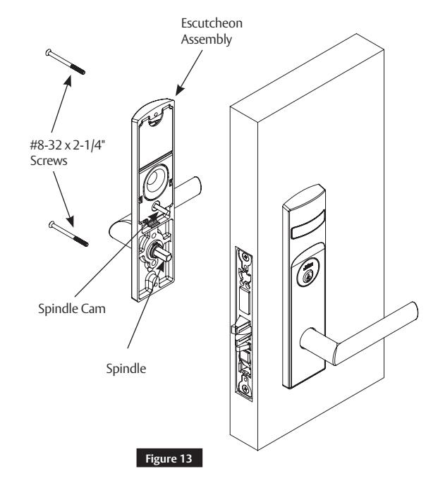
1. Install inside escutcheon assembly Using two (2) through-bolt screws. (Figure 13)
NOTE:
Engage both spindle and spindle cam with lock body.
2. Verify indicator is in unlocked position.
Note:
- Screw heads should be visible on inside escutcheon.
- If a turn-piece is required, it should be oriented vertically.
Used with VN Escutcheon Trim and V Series Indicators
Installation Instructions

5 Installation Instructions (cont.)
f STANDARD LEVERS ONLY: Attach Levers
- 1. Install outside lever or knob by inserting adjustment bolt on opposite side of door. Tighten bolt finger-tight and loosen a few turns.
- 2. Install inside lever or knob by inserting dowel screw. ( Figure 14)
NOTE:
Use correct spindle orientation. ( Figure 15 )
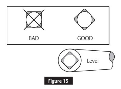
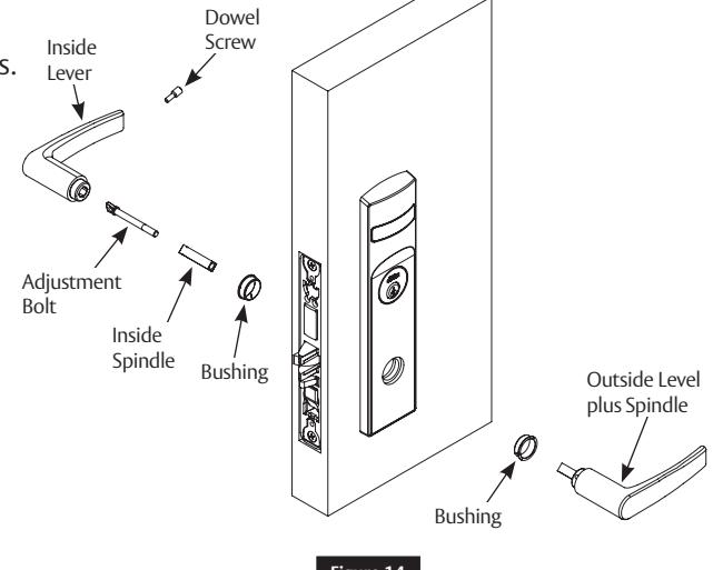
Figure 14
NOTE:
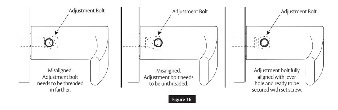
Make sure adjustment bolt hole is aligned with lever or knob hole. (Figure 16 )
Used with VN Escutcheon Trim and V Series Indicators
Installation Instructions

5 Installation Instructions (cont.)
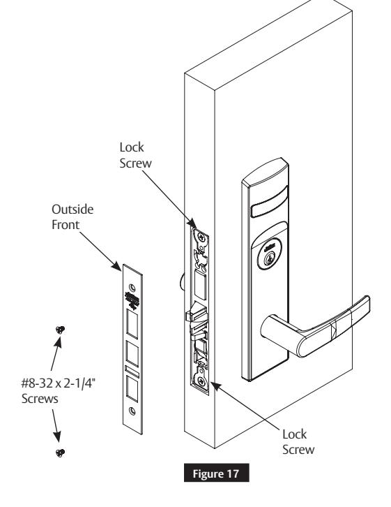
g Install Outside Front
- 1. Tighten the two (2) lock screws completely.
- 2. Attach the outside front with two (2) flat head screws #8-32 x 1/4". (Figure 17)
For installation assistance contact Corbin Russwin
h Perform Functional Check
-
1. Insert key into cylinder and rotate.
- There should be no friction against lock case or any other obstructions.
-
2. Check that key retracts latch.
- Key should rotate freely.
-
3. Throw deadbolt (if present).
- Check that key retracts both deadbolt and latch.
-
4. Test inside lever.
- Ensure it retracts latch and deadbolt (if installed).
- 5. Verify indicator displays correct status when locked and unlocked. See step 4 if it does not.
Used with VN Escutcheon Trim and V Series Indicators
Installation Instructions

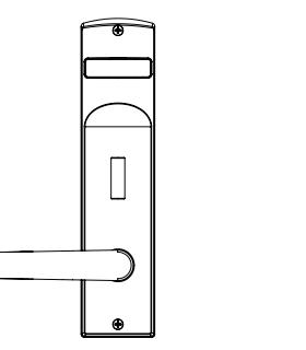
6 Indicator Parts
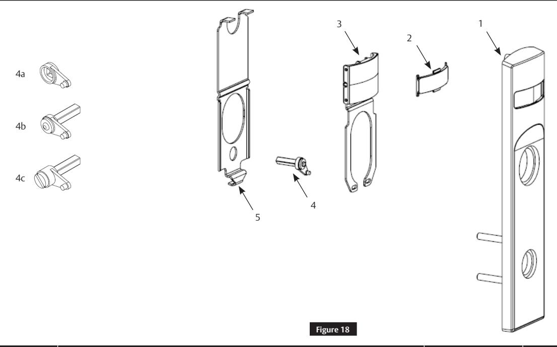
| Figure 18 | Description | Part Number | Required |
|---|---|---|---|
| 1 | VN Indicator Escutcheon | Consult Factory | 1 |
| 2 | Indicator Window | 856F049 | 1 |
| 3 | Indicator Display Assembly – Green 'Unlocked' / Red 'Locked' | 858F241 | 1 |
| Indicator Display Assembly – Green ' Vacant' / Red 'Occupied' | 858F251 | ||
| Indicator Display Assembly – Green Unlocked Icon / Red Locked Icon | 858F261 | ||
| Indicator Display Assembly – White 'Unlocked' / Red 'Locked' | 858F271 | ||
| Indicator Display Assembly – White ' Vacant' / Red 'Occupied' | 858F281 | ||
| Indicator Display Assembly – White Unlocked Icon / Red Locked Icon | 858F291 | ||
| 4A | Indicator Spindle Cam – Thumb Turn | 855F619 | 1 |
| 4B | Indicator Spindle Cam – Cylinder / No Input/Bank | 855F707 | 1 |
| 4C | Indicator Spindle Cam – Coin Turn | 855F747 | 1 |
| 5 | Indicator Escutcheon Back Plate | 855F638 | 1 |
| 6 | VN Escutcheon Screw Pack (Not shown) | 858F517 x finish | 1 |
| 7 | Door Marker Template (Not shown) | FM500 | 1 |
NOTE:
For installation assistance contact Corbin Russwin
Reference ML2000 parts manual for all lock body parts.
in part without the express written permission of ASSA ABLOY Access and Egress Hardware Group, Inc. is prohibited.
Used with VN Escutcheon Trim and V Series Indicators
Installation Instructions

Page intentionally left blank.

Corbin Russwin, Inc. 225 Episcopal Road Berlin, CT 06037 USA Phone: 800-543-3558 Fax: 800-447-6714 www.corbinrusswin.com