


G10 SERIES KNOB TRIM
For use with ED8000 Series Pushbar Exit Device (Wood and Metal Doors)
FM 553 04/12
* IMPORTANT:
- Failure to follow these instructions could affect operation of this product and void warranty.
- Exit devices must be securely fastened to properly reinforced doors with fasteners which will not loosen or pull out. Add reinforcement when necessary.
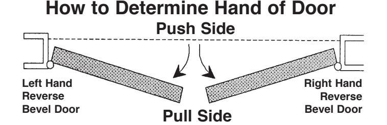
- Before Installing: Be sure exit device is proper hand for door.
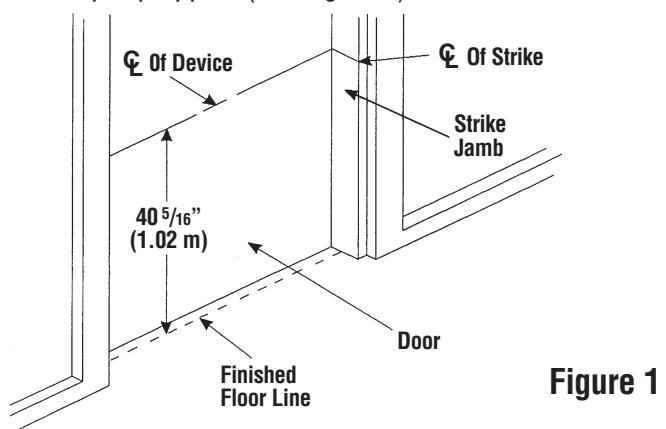
1. Mark Centerline:
Establish centerline of device by drawing line across door and stop, 40-5/16" (1.02 m) above finished floor unless doors have been pre-prepped. (See Figure 1).
2. Prepare Door
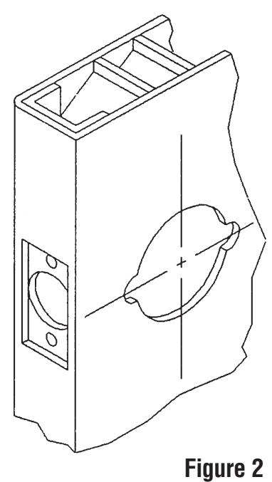
A. For doors prepped with ANSI A115.1 cylindrical lock cut-out:
No further mounting or prep holes are required (See Figure 2).
B. For non-prepped doors: Use template furnished to spot and drill 2-1/8" (54 mm) hole through door.
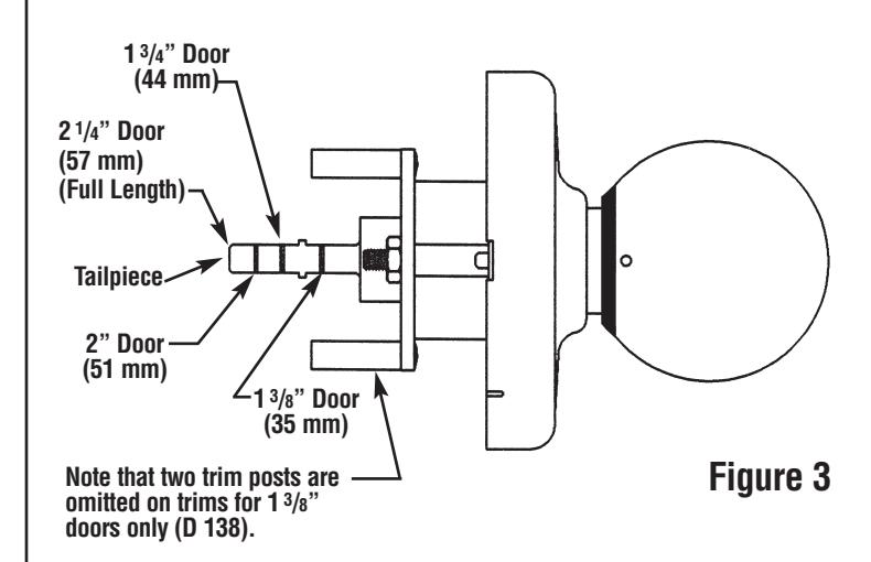
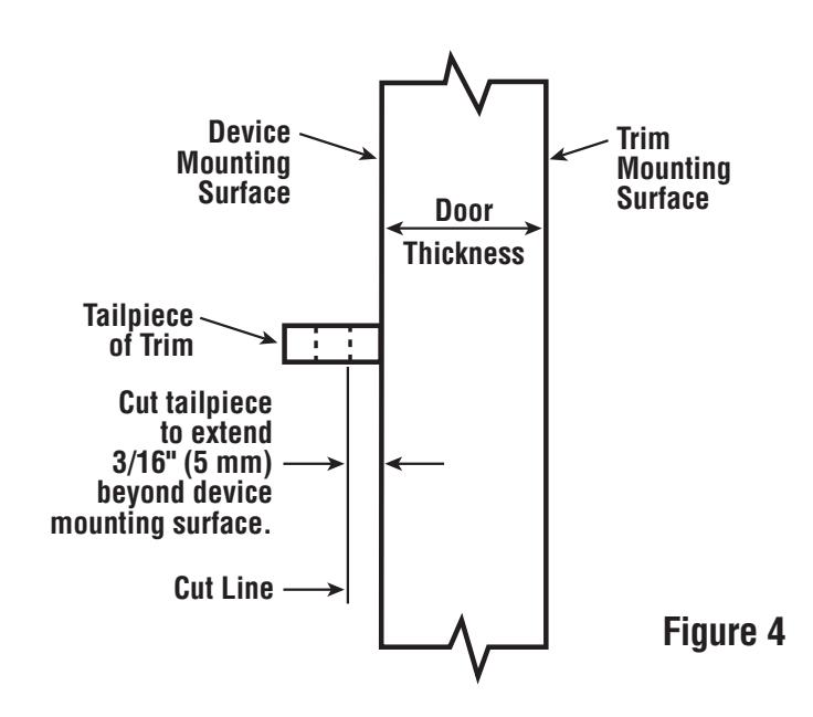
3. Prepare Trim:
A. Use break-off grooves (See Figure 3) or cut trim tailpiece to extend 3/16" (5 mm) beyond device mounting surface which is the door face or shim surface. (See Figure 4).
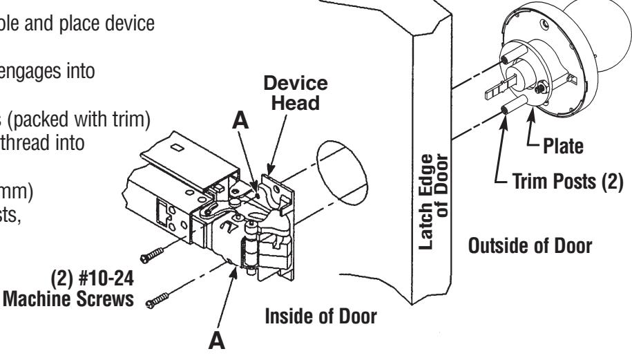
4. Install Trim:
A. Insert trim into 2-1/8" (54 mm) hole and place device against inside surface of door. Be sure tailpiece of trim assembly engages into
cross hole of cam in device head.
B. Insert (2) #10-24 machine screws (packed with trim) into holes "A" of device head and thread into trim posts.
Note: Since trim for a 1-3/8" (35 mm) door does not come with trim posts. machine screws thread directly into plate.
C. Continue with instructions packed with bar.
(The knob retainer will be in
one of these positions)
OR HERE
CT-27
Pliers
HERE
Knob
TO REMOVE AND REINSTALL CYLINDER IN KNOB:
1. Remove Knob:
- A. Insert kev in cylinder and turn 45 degrees clockwise.
- B. Insert knob release tool into hole on side of knob and depress knob retainer.
- C. While retainer is depressed, pull knob off.
2. Remove Cylinder from Knob:
- A. Remove black filler cover.
- B. Remove retaining ring being careful not to scratch knob shank adapter. Use Corbin Russwin retaining ring pliers catalog number CT-27 or equivalent.
- C. Remove knob shank adapter and slide cylinder out of knob.
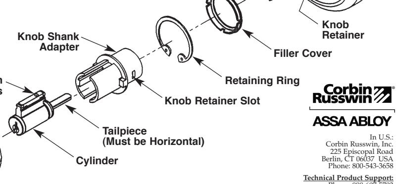
3. Reinstall Cylinder in Knob:
- A. Cylinder tailpiece must be horizontal as shown. Reposition if necessary.
- B. Slide cylinder into knob, locating pin chambers in center slot of knob.
- C. Assemble knob shank adapter over cylinder with slotted end towards. and in line with, pin chambers.
- D. Insert retaining ring against flange of adapter, being sure ring is properly seated in knob groove. Use Corbin Russwin pliers CT-27 or equivalent.
- E. Snap black filler cover on back of knob, making sure slot on cover is aligned with knob hole and knob retainer slot. Check Alignment: Release tool should pass through
knob hole, filler cover and knob retainer slot.
4. Reinstall Knob:
A. Insert key part way. Slide knob onto rollback as far as it will go. Knob retainer on rollback must be aligned with slot in knob shank adapter. Chambers
B. Insert key fully and turn 45 degrees clockwise. Push knob the rest of the way on rollback, then pull back until knob retainer engages.
C. Remove key and pull knob to be sure it is properly retained on rollback.
Rollbac
Knob Retainer Hole
Chassis
Release Tool
ASSA ABLOY Door Security Solutions Canada 160 Four Valley Drive Vaughan, Ontario, Canada L4K 4T9 Phone: 800-461-3007