


Installation Instructions

FE6600 and BL6600 Series
Freewheeling Lever with Escutcheon Trim
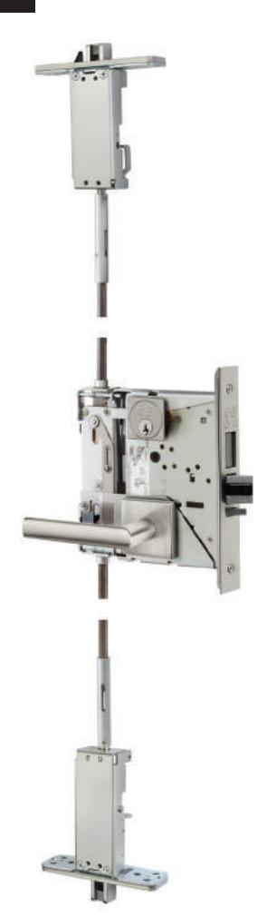
Multi-Point Lock

This product can expose you to lead which is known to the state of California to cause cancer and birth defects or other reproductive harm. For more information go to www.P65warnings.ca.gov.
Multi-Point Lock
Installation Instructions

| TOC | Table of Contents | |
|---|---|---|
| 1 | Tools Required 2 | |
| 2 | Package Contents 3 | |
| 3 | Installation 4 | |
| a | Install Lockbody 4 | |
| b | Assemble Outside Escutcheon 4 | |
| c | Assemble Adapter and Plate 4 | |
| d | Secure Cylinder 5 | |
| e | Inside Escutcheon 5 | |
| f | Inside Lever 5 | |
| 4 | Changing Hand of Trim 6 |
1 Tools Required
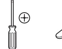
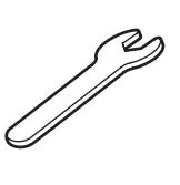
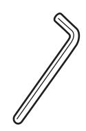
Phillips Screw Driver 3/8" Wrench 5/32" Allen Wrench
Multi-Point Lock
Installation Instructions

Package Contents
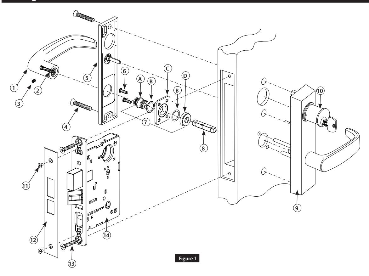
| Figure 1 | Description | Qty. |
|---|---|---|
| 1 | Inside Lever | 1 |
| 2 | Spring | 1 |
| 3 | Set Screw | 1 |
| 4 | Thru-bolt Screws (1/4"-20 x 1-3/4) | 2 |
| 5 | Inside Escutcheon Plate | 1 |
| 6 | Screws & Lock Washers (#8-32 x 5/8") | 2 |
| 7 | Adapter & Plate Assembly | 1 |
| 7A | Adapter | 1 |
| 7B | Washers | 2 |
| 7C | Mounting Plate | 1 |
| 7D | Retaining Nut | 1 |
| 8 | Lever Spindle | 1 |
| 9 | Outside Escutcheon Assembly | 1 |
| 10 | Cylinder | 1 |
| 11 | Screws (#8-32 x 1/4") | 2 |
| 12 | Front Plate | 1 |
| 13 | Lockbody Screws (#12 x 1-1/4") | 2 |
| 14 | Lockbody | 1 |
Installation Instructions

3 Installation
a Install Lockbody
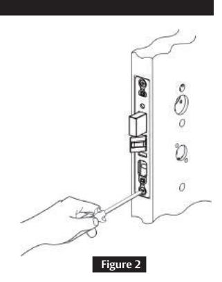
Insert lock body into mortise cutout. Hold loosely in place with (2) lock body screws.
Note:
Do not tighten screws fully at this time. ( Figure 2 )
b Assemble Outside Escutcheon
-
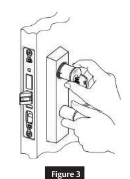
1. With outside lever horizontal, carefully insert mounting posts through the door and lock body.
- Make sure spindle is properly engaged in the lock.
- Outside escutcheon assembly should be flush with door surface.
If cylinder is not included in this function, proceed to Step 3c.
2. Screw cylinder into lock body until flush with escutcheon face. ( Figure 3 )
c Assemble Adapter and Plate
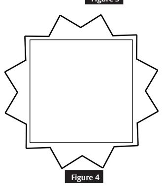
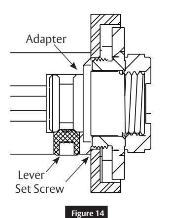
- 1. Tighten retaining nut on inside of mounting plate and adapter as far as it will go by hand, then back off retaining nut one notch until star pattern lines up with square corners. ( Figure 4)
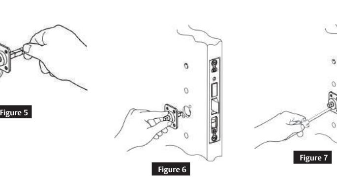
- 2. Insert lever spindle into adapter and plate assembly so that it is held in place. ( Figure 5 )
- 3. Insert inside adapter and plate assembly with lever spindle into square hole on inside of door. (Figure 6 )
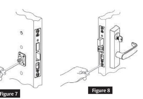
- 4. Now tighten two screws on the inside adapter and plate assembly. Do not over tighten. ( Figure 7)
- 5. Tighten the lockbody screws. ( Figure 8 )
or in part without the express written permission of ASSA ABLOY Access and Egress Hardware Group, Inc. is prohibited.
Installation Instructions

3 Installation (continued)
d Secure Cylinder
- 1. With the cylinder screwed flush into the escutcheon face, check that the keyway is vertical. This ensures that the cylinder retainer fork will line up with the notch on the side of the cylinder.
- 2. Tighten the cylinder retainer to secure the cylinder.
- 3. Turn the key in the cylinder to make certain that the lock functions correctly.
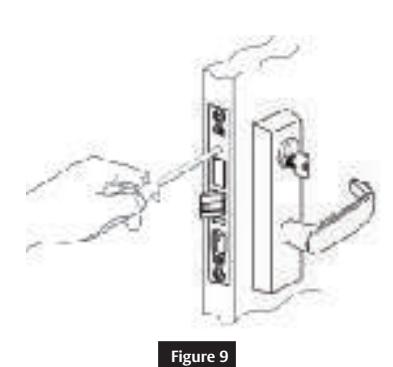
- 4. Secure the outside front plate to the lockbody. ( Figure 9)
e Inside Escutcheon
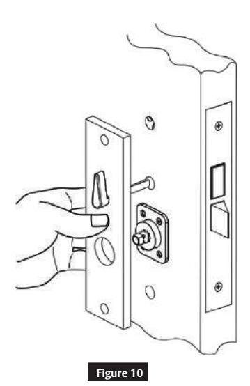
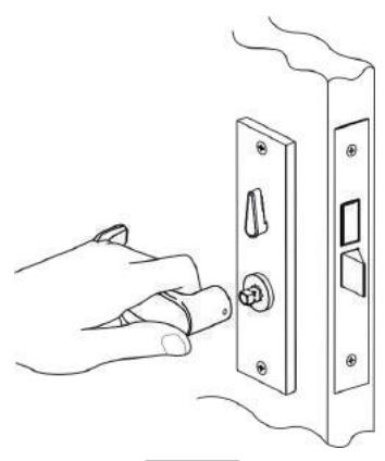
- 1. Place inside escutcheon flat against door. Align thumb turn (if provided) with slot in lock body. ( Figure 10 )
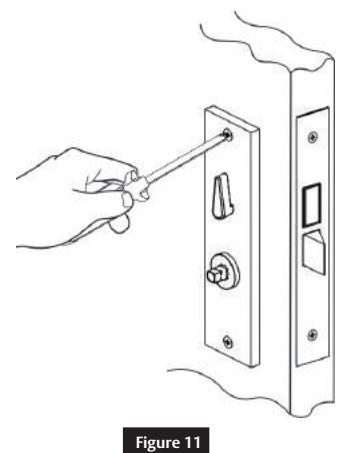
- 2. Secure the inside escutcheon to the outside escutcheon using thru-bolt screws provided. ( Figure 11 )
Multi-Point Lock
Installation Instructions

3 Installation (continued)
f Inside Lever
- 1. Place inside lever horizontally onto lever spindle. Hold lever firmly against the escutcheon. (Figure 12 )
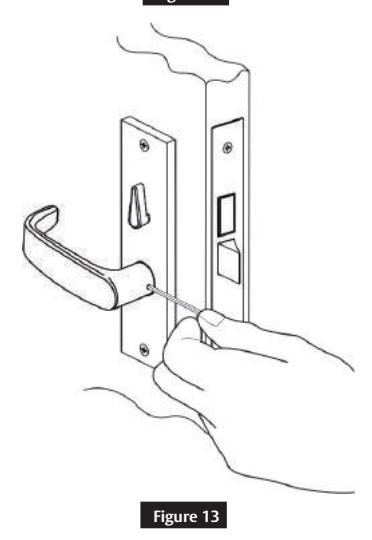
- 2. Use the 1/8" Allen wrench to tighten the set screw securely. Set screw should seat in the groove of the inside adapter. ( Figure 13 )
- 3. Pull on lever to test if set screw is properly secured. ( Figure 14 )

Multi-Point Lock
Installation Instructions

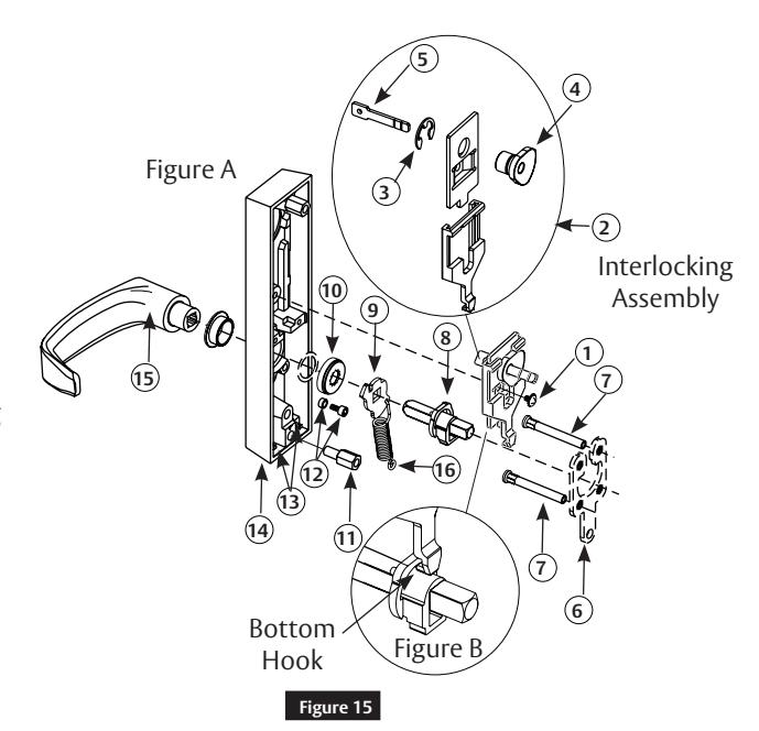
4 Changing Hand of Trim
Loosen screw (1) and remove interlocking assembly (2). ( Figure 15A )
Always wear eye protection while working.
- 1. Unscrew the lower thru-bolt stud (11) with a 3/8" wrench.
- 2. Remove mounting plate (6) and mounting posts.
- 3. Switch mounting posts (7) so they occupy the opposite positions on the mounting plate (6).
- 4. Note the original position of the extension spring (16) and lower plate (9) in the escutcheon (14). Unhook the extension spring from pin (13).
- 5. Remove spring (16), lower plate (9) and locking hub (8) assembly together.
- 6. Detach extension spring (16) from lower plate (9) and locking hub assembly (8).
- 7. Flip lower plate on locking hub assembly spindle so that the spring hole is on the opposite side.
- 8. Reattach hook end of spring to lower plate.
- 9. Unscrew cap screw w/spacer (12) using a 5/32" Allen wrench.
- 10.Move to opposite hole and tighten firmly.
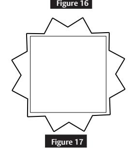
- 11.Rotate lever to position shown in Figure 16 for desired hand.
- 12.Tighten retaining nut (10) firmly by hand and then back off one notch until pattern shown in Figure 17 appears.
- 13.Attach bottom of spring (16) (closed loop) to pin (13). Hold lever horizontal while inserting locking hub assembly (8) and lower plate (9) into retaining nut (10) escutcheon with lower thru-bolt stud (11).
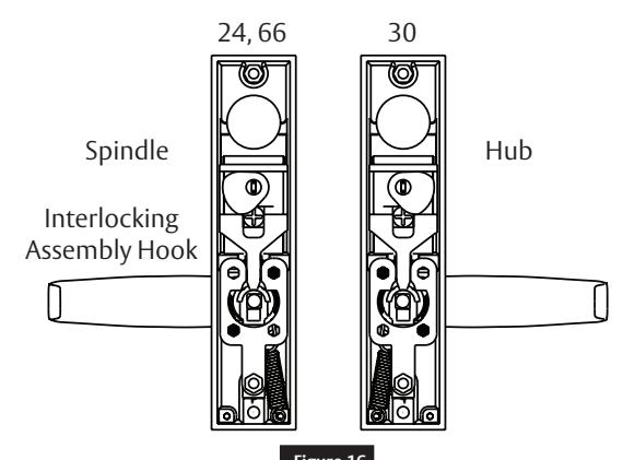
- 14.Refer to Figure 16 : Position hub (4) for required function and hand, and ensure that spindle (5) is vertical. Note position of interlocking assembly hook when positioning hub.
Functions

4 Changing Hand of Trim (continued)
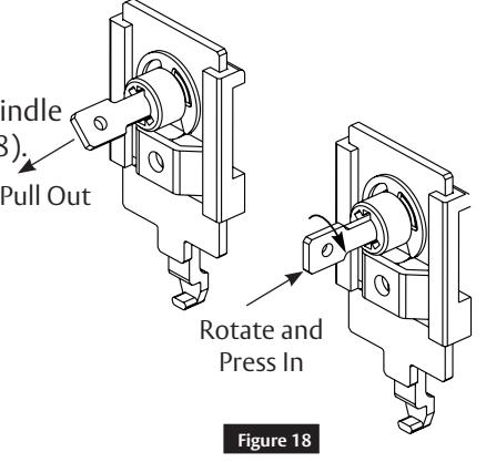
15.Reposition spindle as shown in Figure 18 if necessary.
16.Place the interlocking assembly (2) into the escutcheon and attach the bottom hook to the locking hub (8) as shown in Figure 15 B.
17.Secure in place with screw (1).
Caution:
Check that locking hub (4) moves freely by rotating the hub spindle (5). If not, check that bottom hook is engaged in locking hub (8).
18.Insert and secure mounting plate and mounting posts to escutcheon with lower thru-bolt stud (11).
Corbin Russwin, Inc. 225 Episcopal Road Berlin, CT 06037 USA Phone: 800-543-3658 Fax: 800-447-6714 www.corbinrusswin.com