


Installation Instructions

FE6800 Series
Multi-Point Lock


Multi-Point Lock
Installation Instructions

ASSA ABLOY
This device is intended to be part of an integrated door, frame and hardware assembly UL-approved for both FEMA P-361 (2014), FEMA P-320 (2015) & ICC 500 (2014) guidelines for both in-swing and out-swing doors.
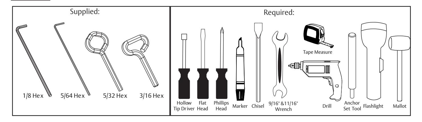
Tools Needed
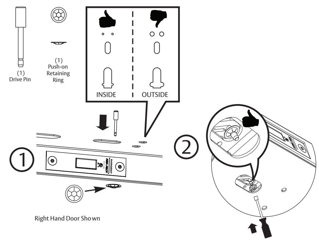
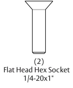
Mounting Hardware (Full Scale)
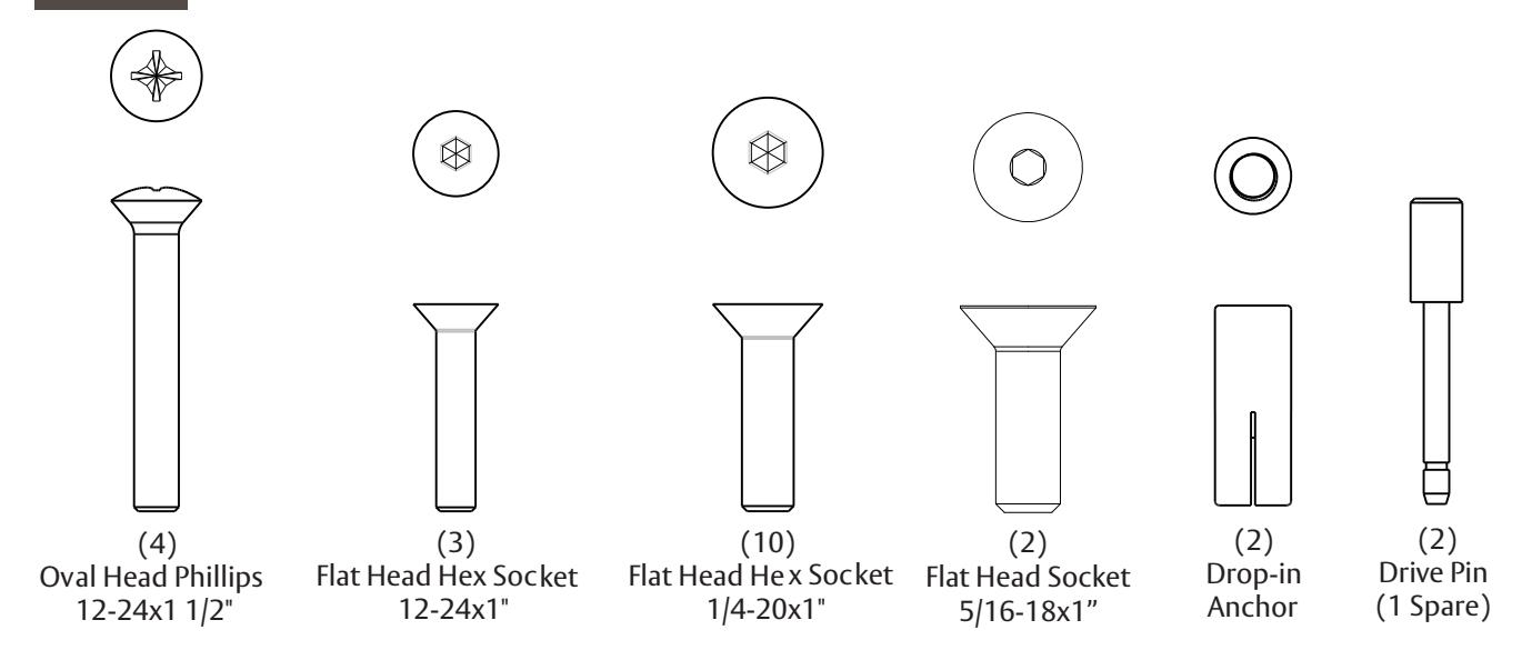

(2) Push-on Retaining Ring (1 Spare)
Multi-Point Lock
Installation Instructions
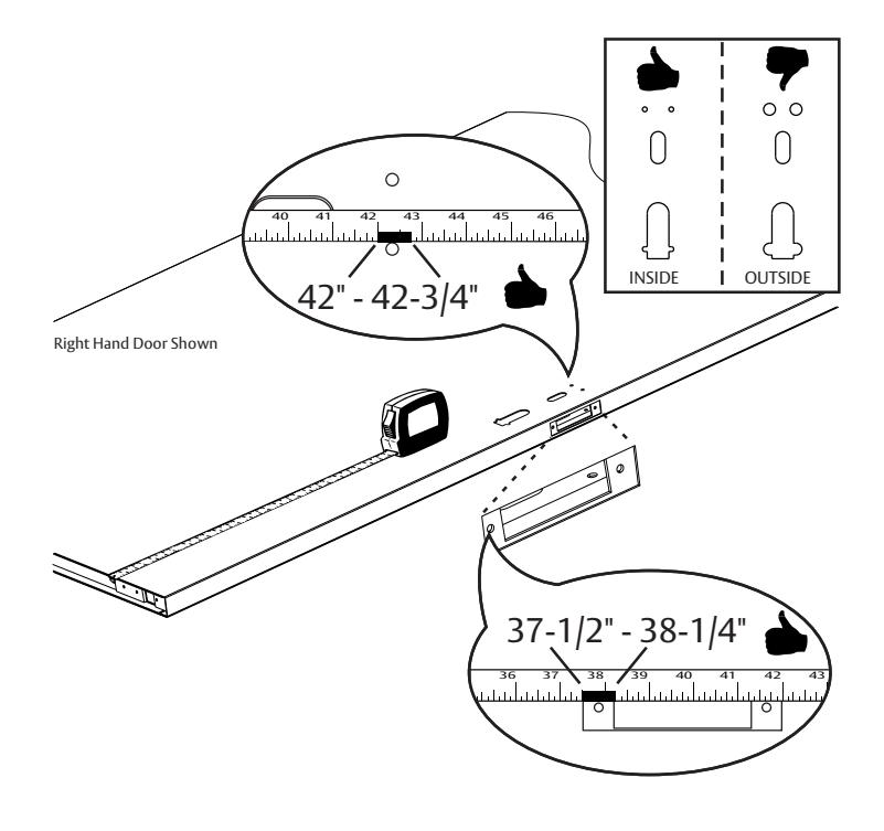
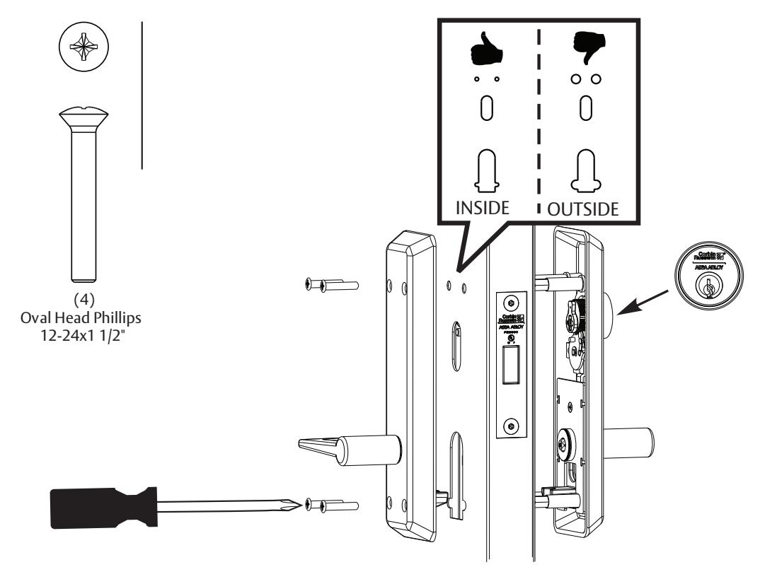
3 Verify Handing

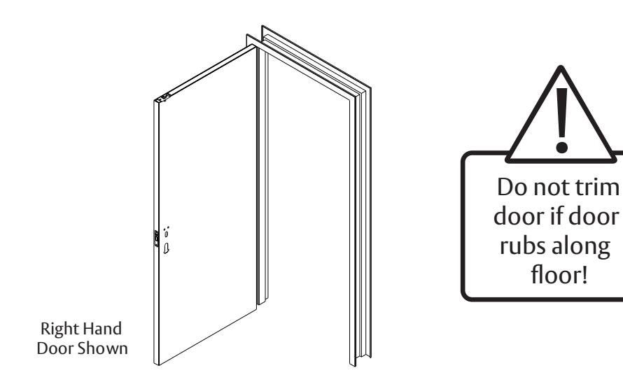
4 Verify Door Dimensions

LOCK IN condition can occur and EMERGENCY EGRESS will be prevented if critical dimensions are not met. Device will not operate, if door cutouts are not within the dimensions below.
Copyright © 2016, 2022, ASSA ABLOY Access and Egress Hardware Group, Inc. All rights reserved. Reproduction in whole or in part without the express written permission of ASSA ABLOY Access and Egress Hardware Group, Inc. is prohibited.
Multi-Point Lock
Installation Instructions

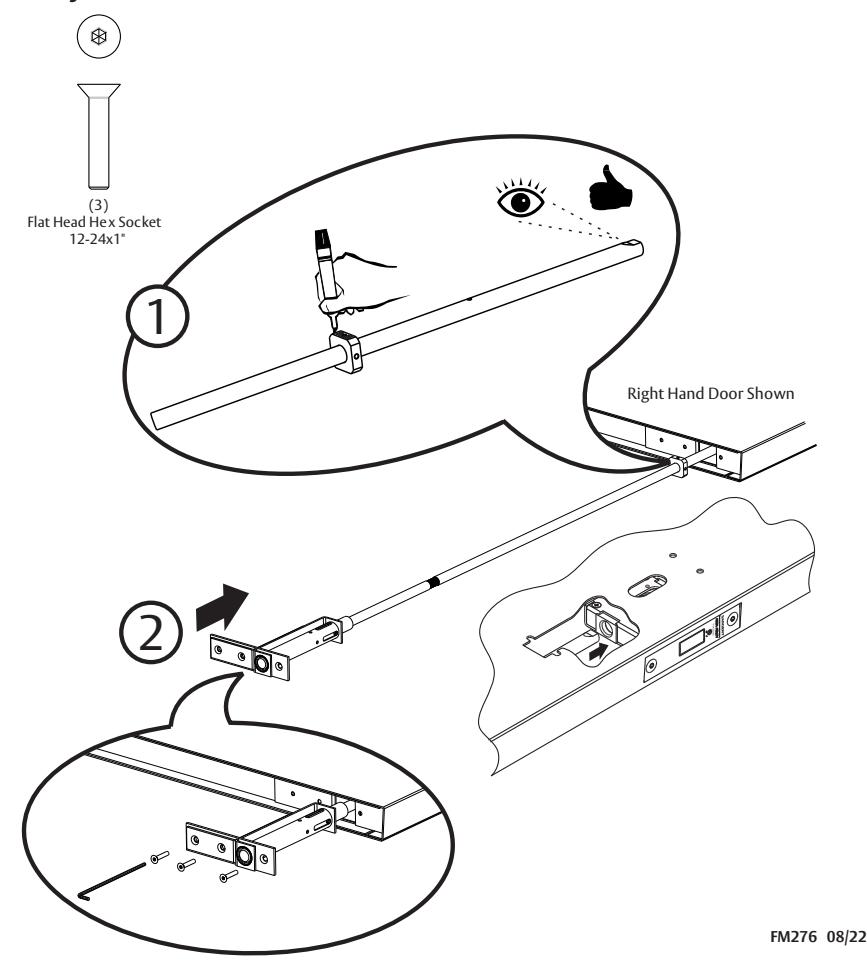
5 Install Deadbolt Assembly


Deadbolt must be retracted before moving to the next step.
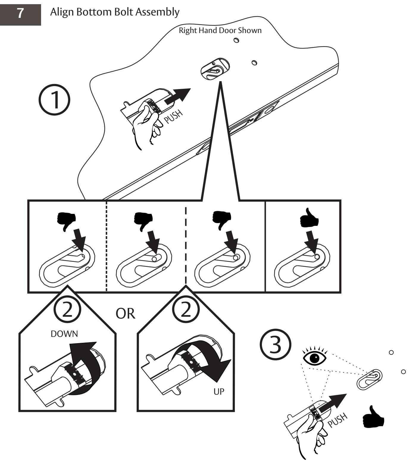
6 Install Bottom Bolt Assembly
For installation assistance contact Corbin Russwin
1-800-543-3658 • techsupport.corbinrusswin@assaabloy.com
Multi-Point Lock
Installation Instructions

Copyright © 2016, 2022, ASSA ABLOY Access and Egress Hardware Group, Inc. All rights reserved. Reproduction in whole or in part without the express written permission of ASSA ABLOY Access and Egress Hardware Group, Inc. is prohibited.
Multi-Point Lock
Installation Instructions

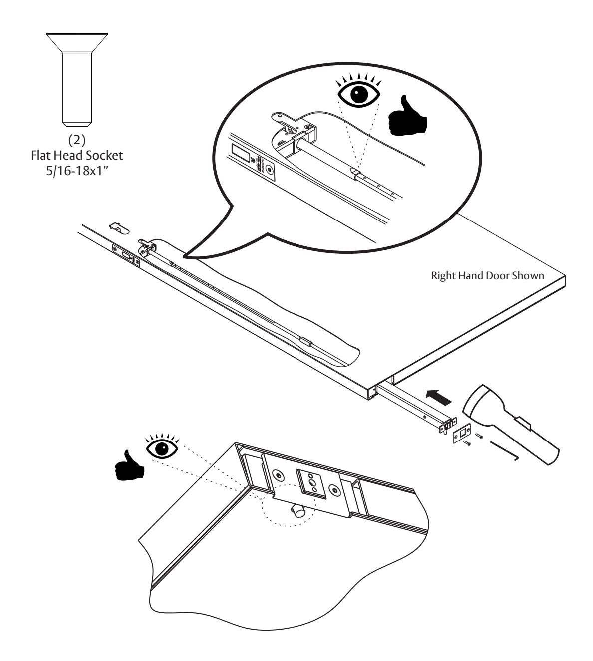
8 Prep Top Assembly

For installation assistance contact Corbin Russwin 1-800-543-3658 • techsupport.corbinrusswin@assaabloy.com
Multi-Point Lock
Installation Instructions

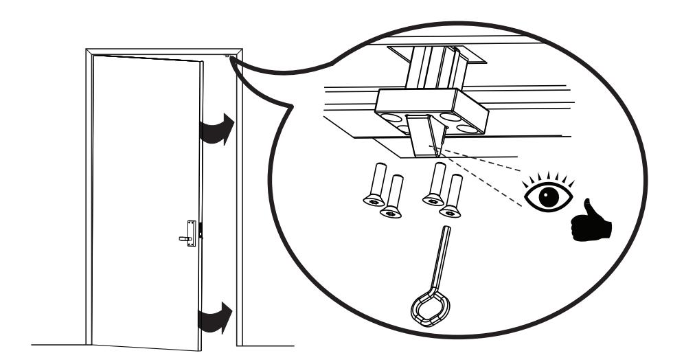
9 Install Top Assembly

For doors manufactured before July 2022, drill & tap top bolt screw holes for 5/16-18 screw threads.
Multi-Point Lock
Installation Instructions

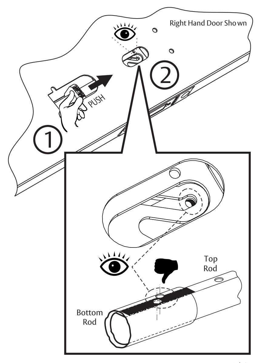
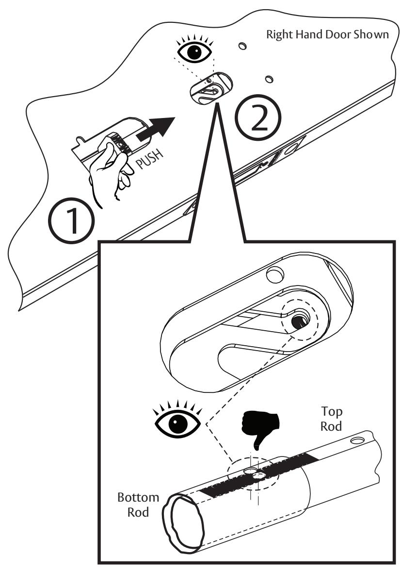
10 Align Top & Bottom Pinning Holes


Multi-Point Lock
Installation Instructions

10a Adjust Misaligned Pinning Holes Up

FM276 08/22 For installation assistance contact Corbin Russwin 1-800-543-3658 • techsupport.corbinrusswin@assaabloy.com
Multi-Point Lock
Installation Instructions

10b Adjust Misaligned Pinning Holes Down

Multi-Point Lock
Installation Instructions

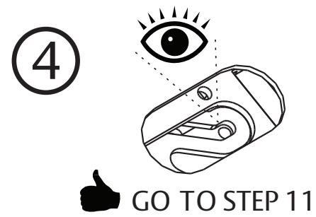
11
Pin Three Assemblies
12
Mount Door to Frame
FM276 08/22
Copyright @ 2016, 2022, ASSA ABLOY Access and Egress Hardware Group, Inc. All rights reserved. Reproduction in whole or in part without the express written permission of ASSA ABLOY Access and Egress Hardware Group, Inc. is prohibited.
Multi-Point Lock
Installation Instructions

13 Check for Hold Open
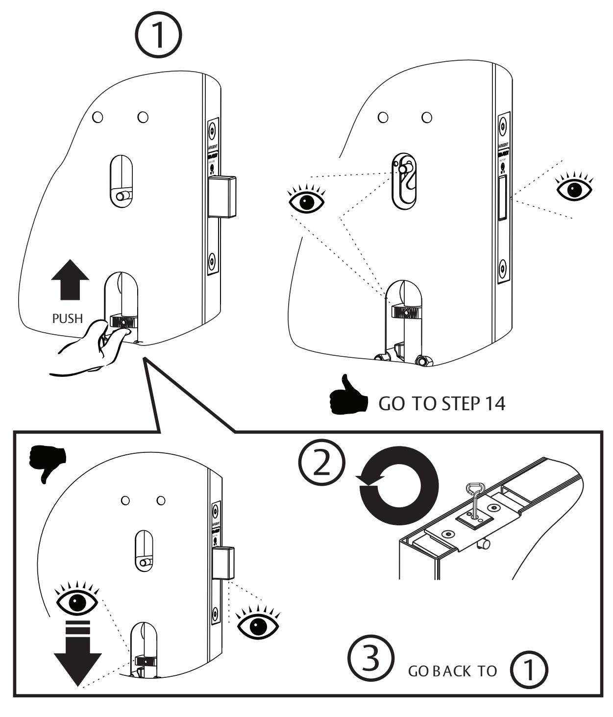
Multi-Point Lock
Installation Instructions

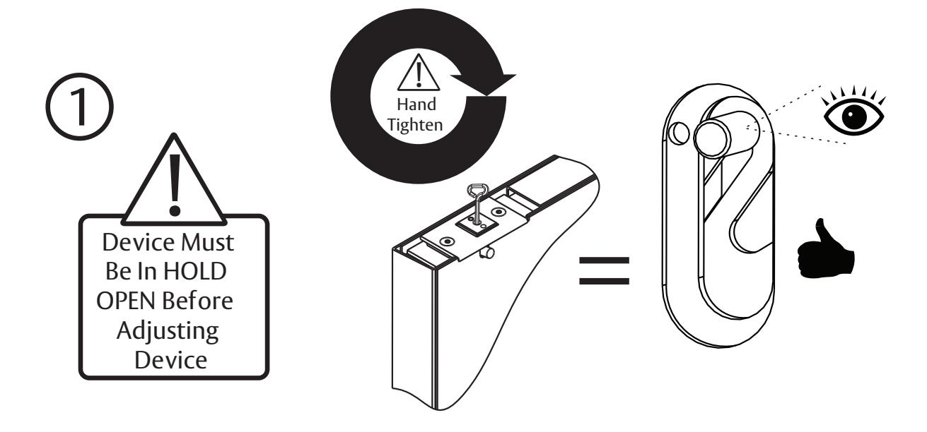
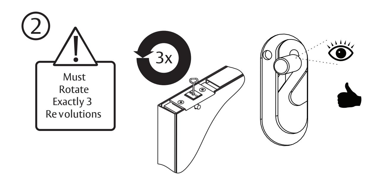
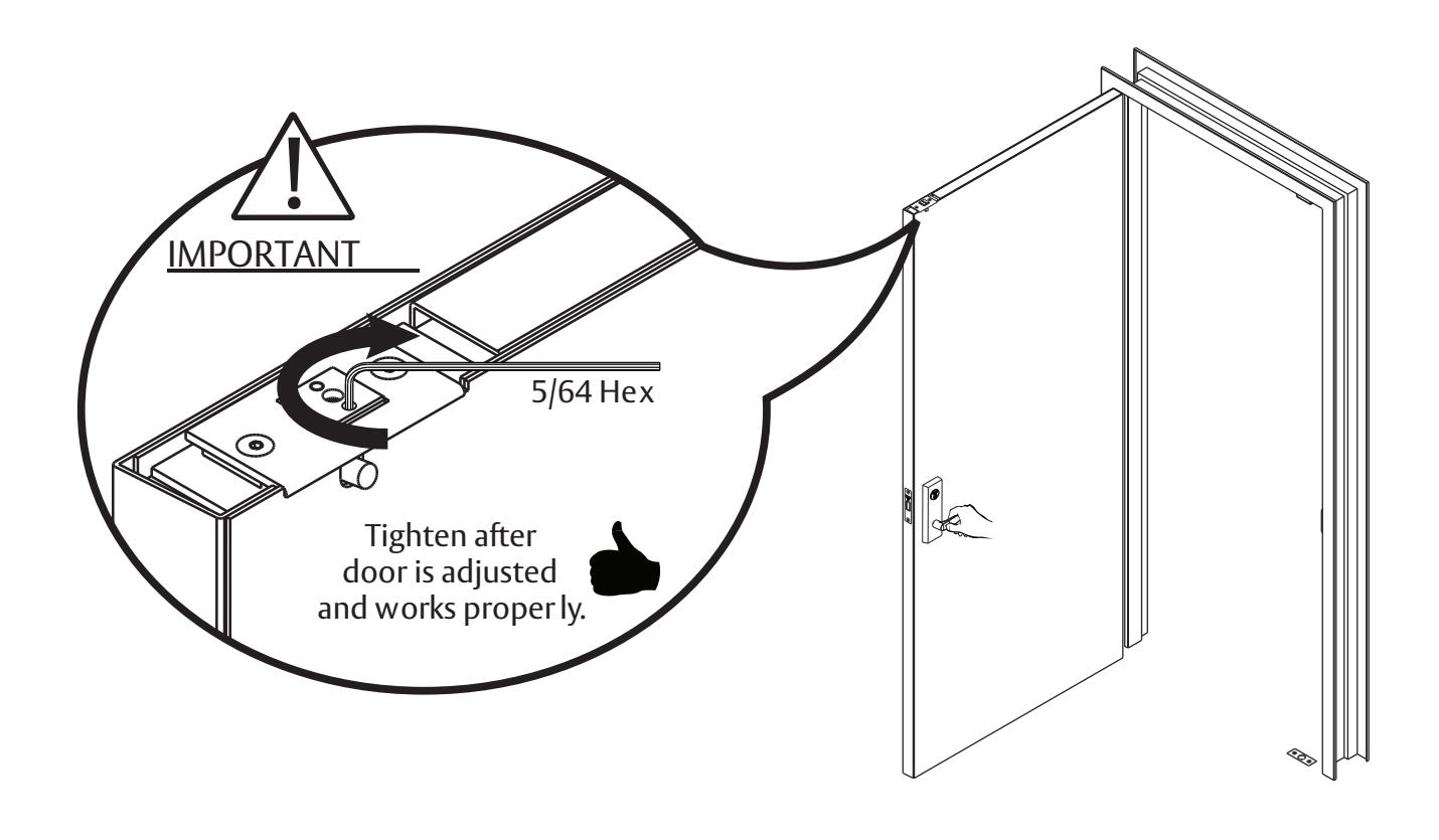
14 Adjust Device
Multi-Point Lock
Installation Instructions

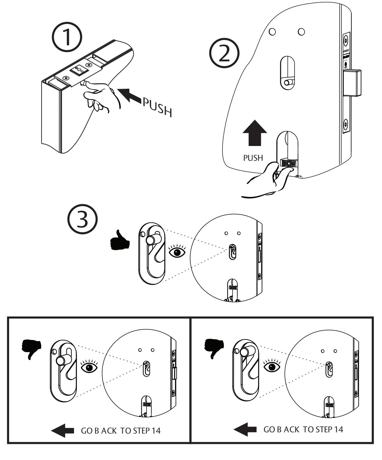
15 Trigger Device & Final Check
Multi-Point Lock
Installation Instructions

16 Assemble Cylinder into Outside Trim
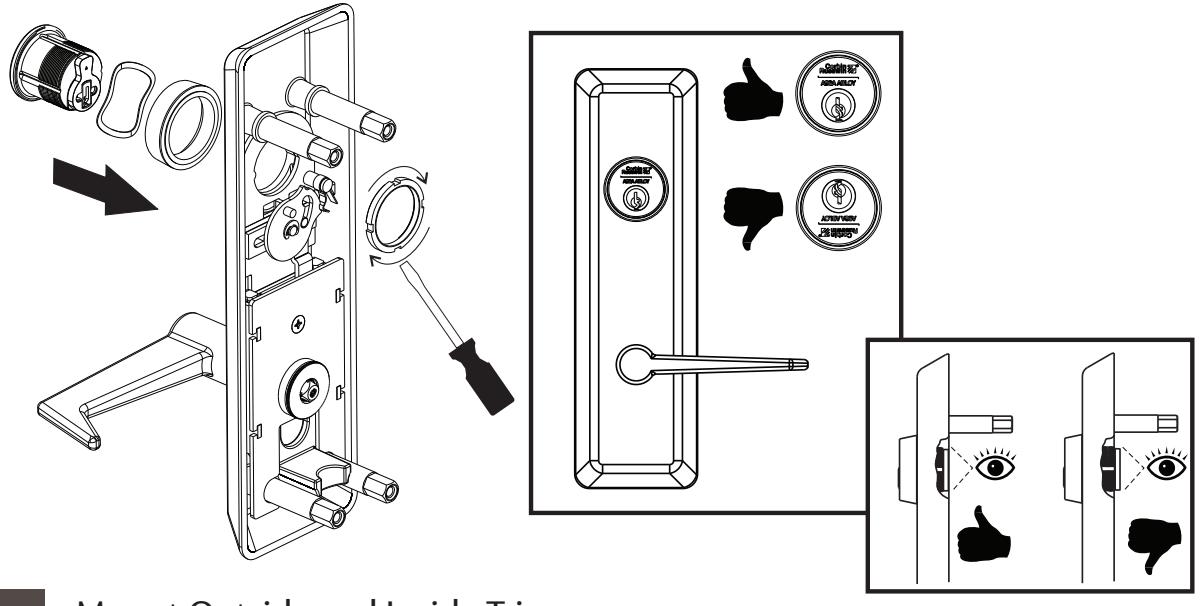
17 Mount Outside and Inside Trim
Multi-Point Lock
Installation Instructions

18 Install Top Latch into Door Frame


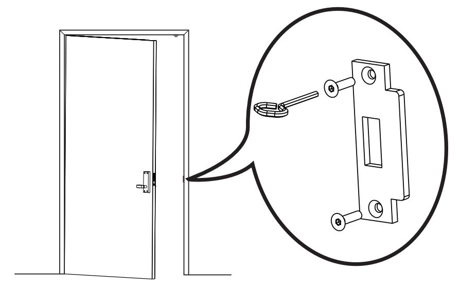
19 Attach Deadbolt Strike Plate to Frame
Multi-Point Lock
Installation Instructions

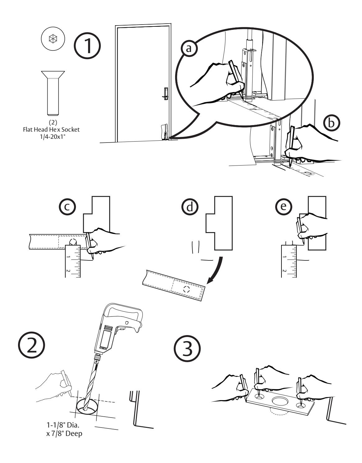
20 Prepare Floor for Bottom Strike
Multi-Point Lock
Installation Instructions

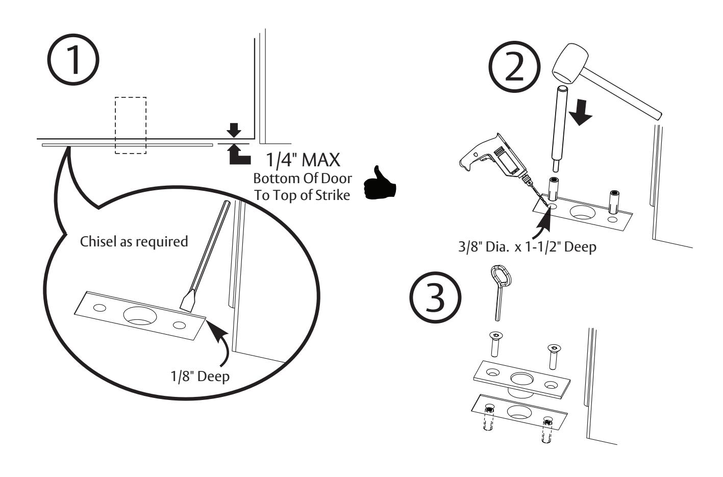
21 Install Bottom Strike
Multi-Point Lock
Installation Instructions

22 Test Installation


This product can expose you to lead which is known to the state of California to cause cancer and birth defects or other reproductive harm. For more information go to www. P65warnings.ca.gov.