


FE6700 Series Multi-Point Lock Installation Instructions for Window Shutter Applications
FM 327 08/17 (617419200)
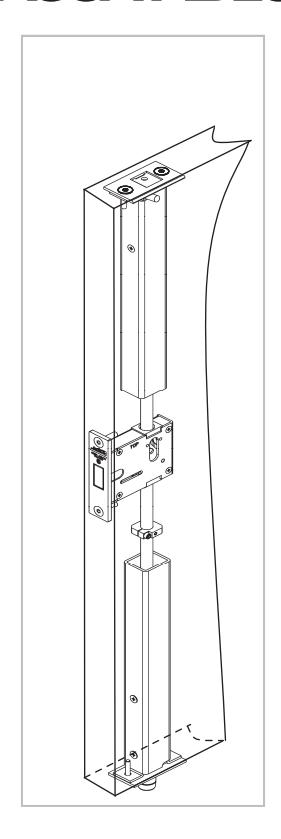
Recommended Installation: Install FE6700 so that the deadbolt is equidistant from the top and bottom of the shutter.

This device is intended to be part of an integrated window shutter, frame and hardware assembly UL-approved for both FEMA 361 and ICC 500 guidelines for inswing window shutters. This instruction sheet will take you through the following steps for full installation.
|
Table
of Contents |
Page |
|---|---|
|
Step
1 – Installation of Deadbolt Assembly |
3 |
|
Step
2 – Installation of Bottom Bolt Assembly 3&4 |
|
|
Step
3 – Installation of Top Pusher Assembly |
4 |
|
Step
4 – Aligning assemblies in preparation for drilling and |
pinning…5&6 |
|
Step
5 – Applying the Drill Jig for proper drilling |
7 |
|
Step
6 – Pinning the Rods to engage the Deadbolt Lever |
8 |
|
Step
7 – Installation of Inside and Outside Trim |
8 |
|
Step
8 – Installation of Cylinder in Outside Trim (Optional) |
9 |
|
Step
9 – Assemble the Top Latc h to the Frame |
9 |
|
Step
10 – Installation of Deadbolt Strike |
10 |
|
Step
11 – Install the Bottom Strike |
10 |


- - Place the window shutter on a horizontal surface with the pin lever notch located at the top of the shutter facing up.
- - The recommended deadbolt assembly location should be equidistant from the top and bottom of the shutter.
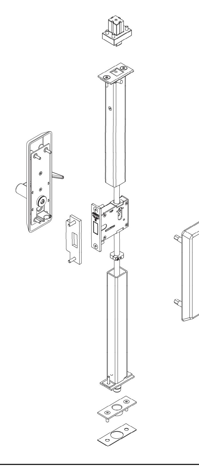
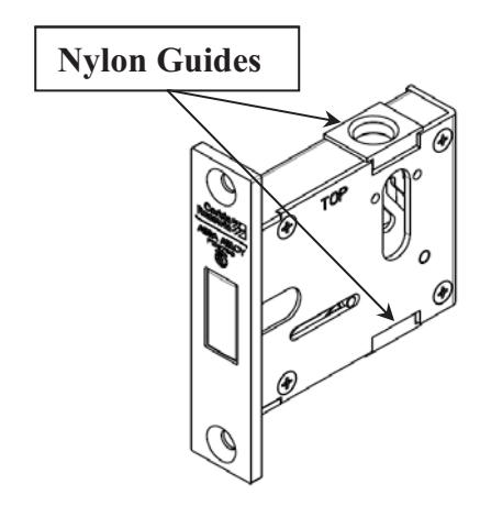
- - Assemble the deadbolt case into the lock pocket provided in the door. Note the orientation of the lock, the top of the deadbolt case indicates that this should be toward the top of the shutter.
- Assemble the lock to the edge of the shutter using (2) 1/4 – 20 by 1" Flat Head Cap Screws.
Step 2 – Installation of the Bottom Bolt Assembly
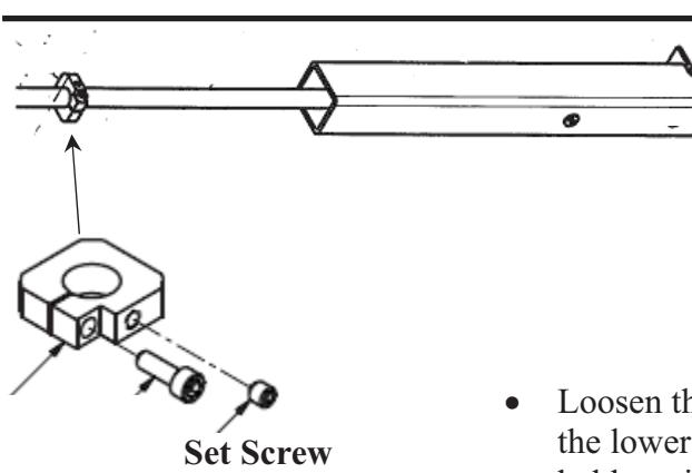
- Loosen the set screw so that the lifting platform will slide along the lower rod tubing but not slide on its own when the rod is held vertically. Be sure that the set screw is oriented so that it will be accessible through the Lower Thru Bolt Cutout on the top side of the shutter.
- - When you insert the assembly into the shutter and through the nylon guides of the deadbolt case this lifting pad will be in a position to allow you to make the final necessary adjustment. Note the orientation of the bottom bolt assembly the double screw head side (not shown in this image) should be facing the hinge side of the shutter.
Continue on next page………….
-
Lower Thru Bolt Cutout
Step 2 – Installation of the Bottom Bolt Assembly continued
- With the Deadbolt Retracted , slide the Bottom Bolt Sub Assembly into the prep. hole in the bottom of the shutter. As you guide the assembly up into the shutter you will need to guide it into the bottom nylon guide of the Deadbolt Assembly and then up thru the top nylon guide.
- Seat the bottom bolt bracket against the shutters lower reinforcement plate.
- Align Bottom Bolt Plate to shutter prep.
- Fasten the Bottom Bolt Assembly and Bottom Bolt Plate to the bottom of the shutter using (2) 5/16-18 by 1" Flat Head Cap Screws.
Assembly
Step 3 – Installation of the Top Pusher Assembly
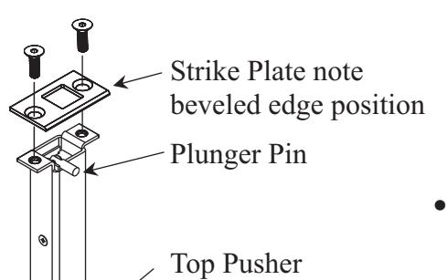
- Slide this assembly into the prep. at the top of the shutter, making sure the plunger pin is oriented with the clearance slot on the stop side of the shutter.
- - Visually align the rod of the Top Pusher Assembly so that it enters the tube of the Bottom Bolt Assembly that extends out of the Deadbolt Assembly.
- - Align the Top Strike plate to shutter prep. Noting the position of the beveled edge. It should be on the same side as the plunger pin.
- - Fasten the Top Strike plate and Top Pusher Assembly to the top of the shutter using (2) 5/16-18 by 1" Flat Head Cap Screws.
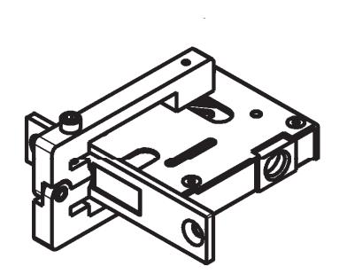
Step 4 – Alignment of components in preparation for drilling and pinning
- Thread the Top Clamp into the threaded hole so that it extends the top latch to the proper position for pinning. The Top Bolt Clamp will assure that the top latch is in the correct position for final installation.
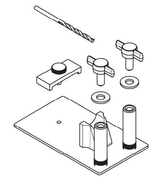
- Prepare the lifting platform installation jig by removing the two wing fasteners and their washers
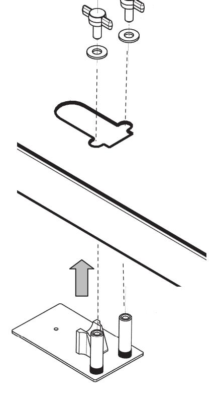
- Introduce the lifting platform jig up through the under side of the shutter as shown
- Using the two wing fasteners and their washers, secure the lifting platform jig to the shutter.
The lifting platform jig will now be in position to allow sliding the lifting platform (shown in step 2) so that it rests against the shelf of the jig.
Continued on next page………….

Step 4 – Alignment of components in preparation for drilling and pinning continued
Before continuing to the next step be certain the top pusher and bottom bolt are in the correct position.
Bottom Bolt should be flush to the bottom of the shutter.
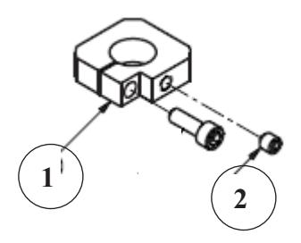
- - The lifting platform (item 1) should be moved down the bottom rod and placed against the shelf of the lifting platform jig.
- - Next secure the platforms position by tightening the cone point set screw (item 2). This will assure the point on the set screw embeds itself firmly into the bottom rod.
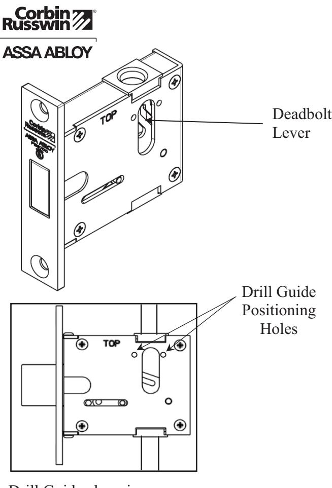
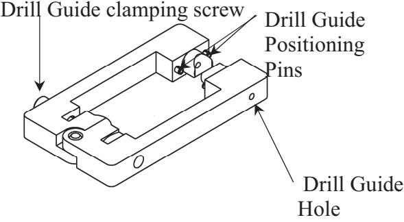
Step 5 – Applying the drill jig for proper drilling
- - Manually project the deadbolt by applying force to the deadbolt lever toward the bottom of the shutter.
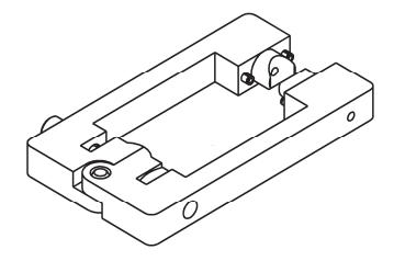
- - The deadbolt lever is now in a position to allow the Drill Guide to be positioned above the deadbolt and fixed into position using the two drill guide positioning holes provided in both sides of the deadbolt case.
- - The Drill Guide is an alligator type jig. Loosen the Drill Guides clamping screw, allowing the jaws to rotate 90 degrees to allow the guide to be positioned above the deadbolt and closed around the shutter so that the pins on both sides of the Drill Guide engage the two Drill Guide Positioning Holes.
- - Once the Drill Guide is engaged in the positioning holes, tighten the Drill Guides clamping screw so that it will firmly secure the jig around the shutter.
- - Using the Drill Guide Hole, drill a 1/8" hole (drill provided with Jig Components) thru both sets of rods.
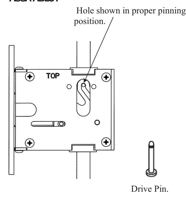
Step 6 – Pinning the Rods to engage the Deadbolt Lever
- - Loosen the Drill Guides clamping screw allowing the Drill Guide to be removed from the shutter.
- - Manually retract the Deadbolt by applying force to the deadbolt lever toward the top of the shutter.
- - This will put the pinning hole in the proper position for fastening the Drive Pin.
- - Insert the drive Pin from the underside of the shutter and through the holes in the rods and fasten the Drive Pin in place with the spring Washer.
The Lifting Platform Jig and the Top Clamp can now be removed from the shutter.
Step 7 – Installation of Inside and Outside Trim
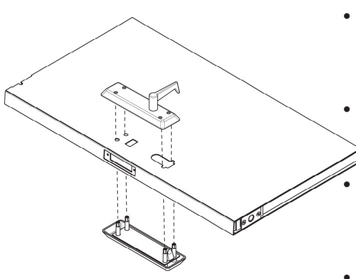
- - Install the outside trim by inserting it from underneath the shutter (outside face).
- As it enters the shutter cavity the lifting pad in the escutcheon will rest on the underside of the lifting pad secured to the rods in step 4.
- Press the outside escutcheon against the shutter surface.
- Install the inside trim by placing it over the shutter prep and positioning the lifting pad of the inside trim on the underside of the lifting pad.
- Visually align the mounting holes of the inside escutcheon to the mounting posts from the outside escutcheon.
- - Insert 4 mounting screws ¼" – 20 by 1 ¾" and tighten screws.

Step 8 – Installation of Cylinder in Outside Trim (Optional)
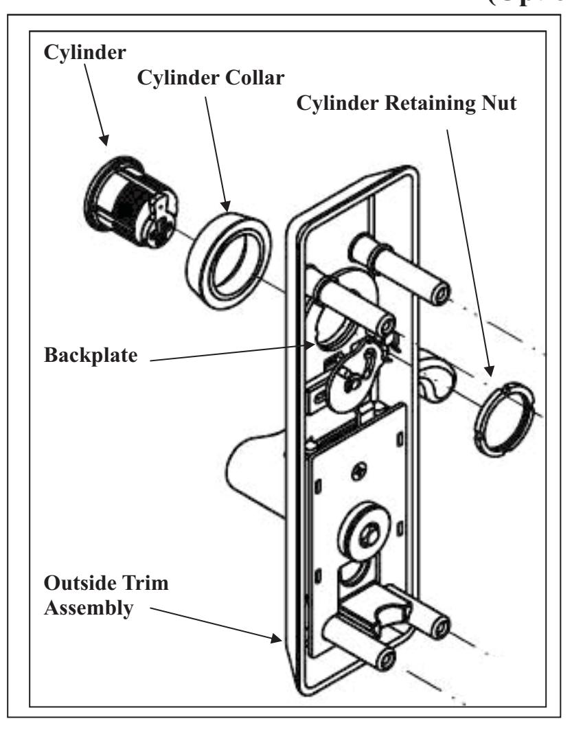
- - Insert the Cylinder into the Cylinder Collar
- - Place the Cylinder Retaining Nut against the backplate of the outside trim assembly,
- - Feed the cylinder and cylinder collar into the cylinder hole of the escutcheon and screw the cylinder retaining nut to the cylinder until it is fully seated with the cam straight up as shown.
- - Secure the cylinder to the escutcheon by tightening the cylinder retaining nut.
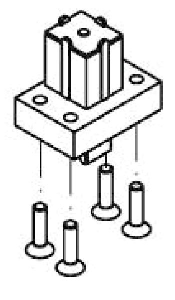
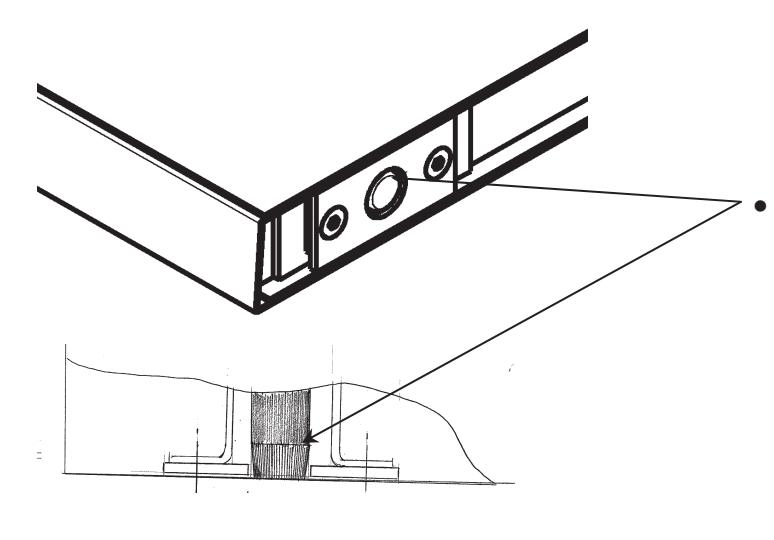
Step 9 – Assemble the Top Latch to the Frame
- Assembly the top latch into the top of the frame using (4) ¼" – 20 by 1" Flat Head Cap Screws. The angled surface should face the shutter.

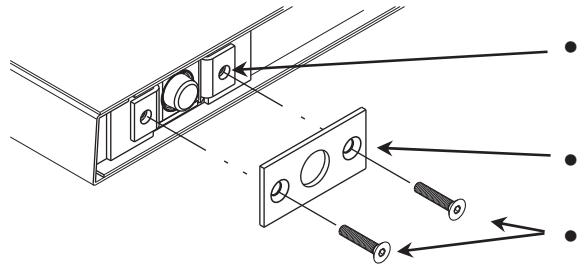
Step 10 – Installation of Deadbolt Strike
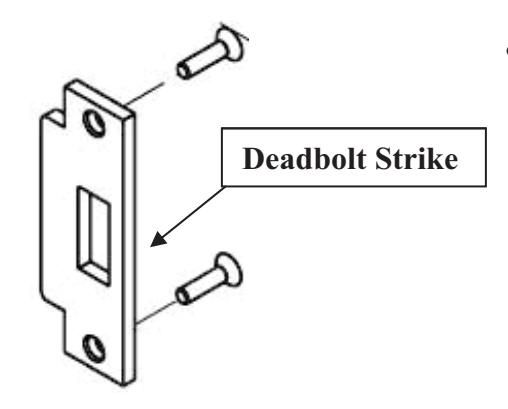
- Assemble the Deadbolt Strike to the frame using (2) ¼" – 20 by 1" Flat Head Cap Screws.
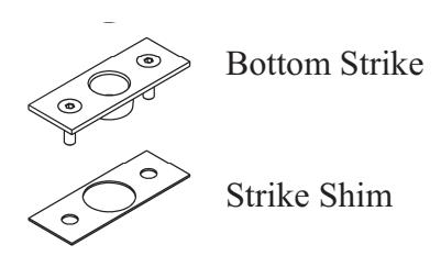
Step 11 – Install the Bottom Strike
- Place the Bottom Strike into the Strike Shim and fasten to the frame using (2) ¼" – 20 Screws
Install the Shutter into the frame assembly and shim for proper shutter gap and for the shutter being square and plumb
END OF INSTALLATION INSTRUCTIONS
225 Episcopal Road 160 Four Valley Drive www.corbinrusswin.com www.assaabloy.ca
Technical Product Support: Telephone: 888-607-5703 Fax: 800-828-7277
In U.S.A.: In Canada:
Corbin Russwin, Inc. ASSA ABLOY Door Security Solutions Canada
Berlin, CT 06037 USA Vaughn, Ontario, Canada L4K 4T9
Copyright © 2017 Corbin Russwin, Inc., an ASSA ABLOY Group company. All rights reserved. Reproduction in whole or in part without the express written permission of Corbin Russwin, Inc. is prohibited.
ASSA ABLOY is the global leader in door opening solutions, dedicated to satisfying end-user needs for security, safety and convenience.