


Multi-Point Lock
FE6600 Series
Important
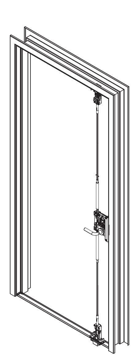
The latches, rods, and cassette are pre-installed. This product must be installed by a factory trained technician.

This product can expose you to lead which is known to the state of California to cause cancer and birth defects or other reproductive harm. For more information go to www.P65warnings.ca.gov.
FE6600 Series
Installation Instructions

| TOC | Table of Contents | |
|---|---|---|
| 1 | Package Contents 4 | |
| 2 | Tools Required 5 | |
| a | Tools Required for Electronic Access Control Shield 5 | |
| b | Tools Required for Dogging Indicator Option 5 | |
| 3 | Installation 6 | |
| a | Check Door 6 | |
| b | Door Installation 6 | |
| c | Install Top Strike into Door Frame 6 | |
| d | Install Center Strike into Door Frame7 | |
| e | Remove Retractor Inserts 7 | |
| f | Check Latches (uninstalled) 7 | |
| g | Install Bottom Strike 8 | |
| h | Top and Bottom Latch Adjustment | 10 |
| i | Mortise Lock Install | 12 |
| j | Final Mortise Lock and Trim Installation | 13 |
| k | Electronic Access Control (EAC) Reader and Controller Installation | 13 |
| l | Deadbolt Label Installation | 13 |
| m | Key Override With Deadbolt Function Operation Check | 13 |
| n | Electronic Access Control (EAC) Shield (if applicable) | 14 |
FE6600 Series
Installation Instructions

| 4 | Optional Installation | 14 |
|---|---|---|
| a | Dogging Indicator Installation | 14 |
| 5 | Addendum | 17 |
| a | Check Door | 17 |
| b | Place Door Horizontal on Sawhorse | 17 |
| c | Install Lockbody Cassette | 18 |
| d | Latch Rod Guides | 18 |
| e | Feed Top Rod into Door | 19 |
| f | Align with LBC | 19 |
| g | Troubleshoot Latch Installation | 20 |
| h | Correct Rod Installation Check | 20 |
| i | Secure Top Latch | 21 |
| j | Tighten Set Screw | 21 |
| k | Bottom Latch Installation | 22 |
| l | Check Latch | 22 |
| m | Mortise Reinforcer and Mortise Lock Installation | 23 |
| n | Final Installation | 23 |

1 Package Contents
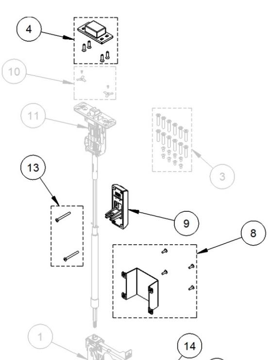
| Part Number | Description | |
|---|---|---|
| 1 | 82-5342 | Multipoint cassette |
| 2 | 82-5345 | Trim mounting screw pack |
| 3 | 82-5346 | Top/bottom case mounting screw pack |
| 4 | 82-5347 | Top strike pack |
| 5 | 82-5348 | Bottom strike pack |
| 6 | 82-5349 | Mortise mounting/reinforcement pack |
| 7 | 82-5350 | Center strike pack |
| 82-5351 | IN/PN Inside cover shield pack | |
| 8 | 82-5352 | Harmony inside cover shield pack |
| 82-5353 | Passport inside cover shield pack | |
| 9 | 188 | Dogging indicator (includes item 13) (specify finish) |
| 10 | 82-5383 | Screw retainer pack |
| 11 | 82-5386 | Top case and rod assembly (specify door size) |
| 12 | 82-5387 | Bottom case and rod assembly (specify door size) |
| 13 | 82-5400 | Dogging indicator screw pack (specify finish) |
| 14 | 01-4597 | T-wrench, adjustment |
| 15 | Consult factory | Outside armor front |
| 16 | Consult factory | Mortise lock |
| 17 | Consult factory | Mortise trim |
| 18 | Consult factory | Cylinder |
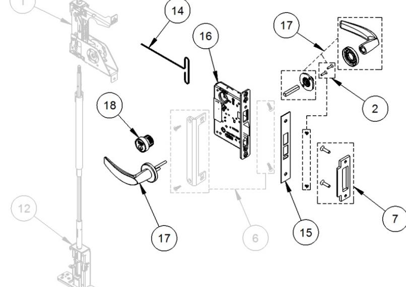
Note:
The grayed parts are preinstalled by the door manufacturer and relate to the Addendum section beginning on page 16.
FE6600 Series
Installation Instructions

2 Tools Required
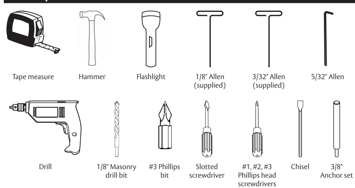
a Tools Required for Electronic Access Control Shield
b Tools Required for Dogging Indicator Option
or in part without the express written permission of ASSA ABLOY Access and Egress Hardware Group, Inc. is prohibited.

3 Installation
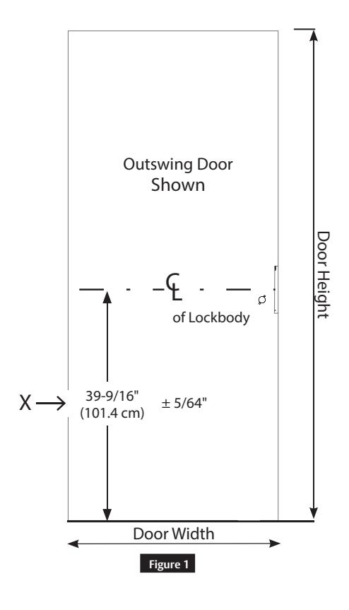
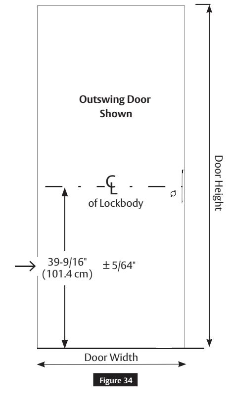
a Check Door
Verify the door is:
- Correct size and hand for opening.
- Correctly prepared to Template 4740.
IMPORTANT
If measurement is incorrect, DO NOT PROCEED WITH INSTALLATION. Contact door manufacturer.
b Door Installation
Hang the door on the frame.
IMPORTANT
If the door rubs along the floor, do not complete this installation! Contact door manufacturer.
For installation assistance contact Corbin Russwin
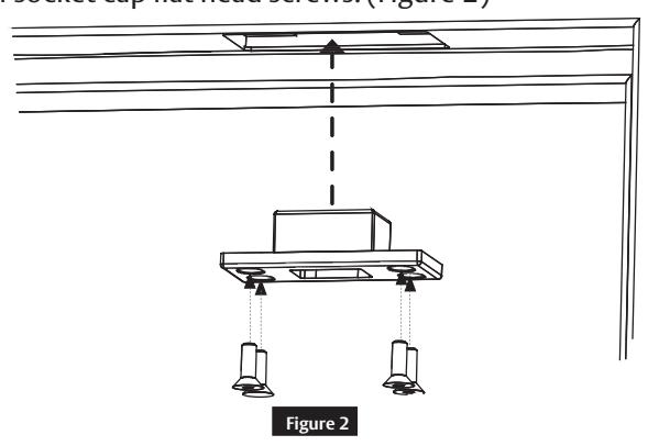
c Install Top Strike into Door Frame
- Remove the strike filler plate and screws and discard.
- Install four (4) #12-24 socket cap flat head screws. (Figure 2)
Copyright © 2017, 2019, ASSA ABLOY Access and Egress Hardware Group, Inc. All rights reserved. Reproduction in whole 1-800-543-3658 • techsupport.corbinrusswin@assaabloy.com
or in part without the express written permission of ASSA ABLOY Access and Egress Hardware Group, Inc. is prohibited.
FE6600 Series
Installation Instructions

3 Installation (cont.)
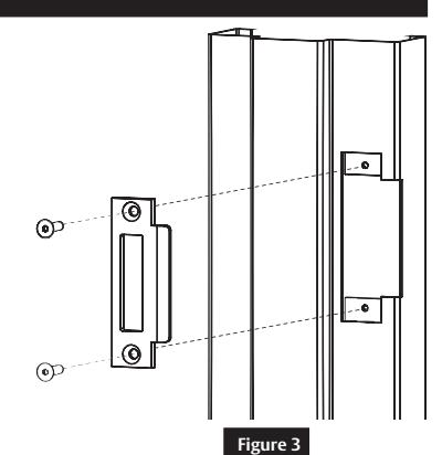
d Install Center Strike into Door Frame
• Install two (2) ¼-20 socket cap flat head screws. ( Figure 3 )
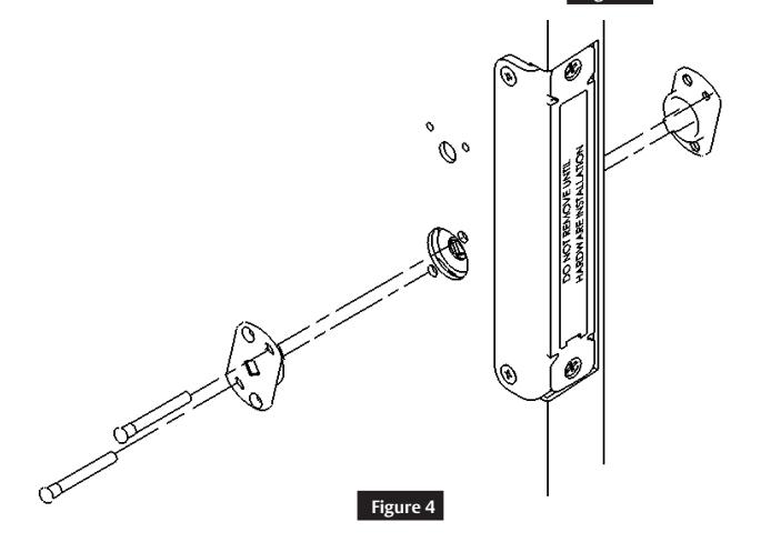
e Remove Retractor Inserts
WARNING
The door now has the ability to latch. (Figure 4 )
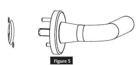
f Check Latches (uninstalled)
or in part without the express written permission of ASSA ABLOY Access and Egress Hardware Group, Inc. is prohibited.
• Insert the uninstalled outside mortise trim and rotate to verify the top and bottom latches retract flush with the door. Do not install mortise trim at this time. (Figure 5)
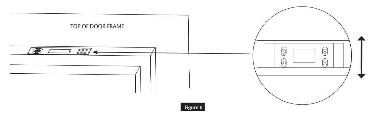
• Move the top strike back and forth until the top latch engages the strike. ( Figure 6 )
7

3 Installation (cont.)
g Install Bottom Strike
• Close the door and mark the location of the bottom bolt.
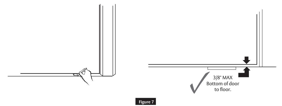
• Open the door and place the strike over the bottom bolt location. Mark the location of the bottom strike pocket and hole locations. (Figure 7)
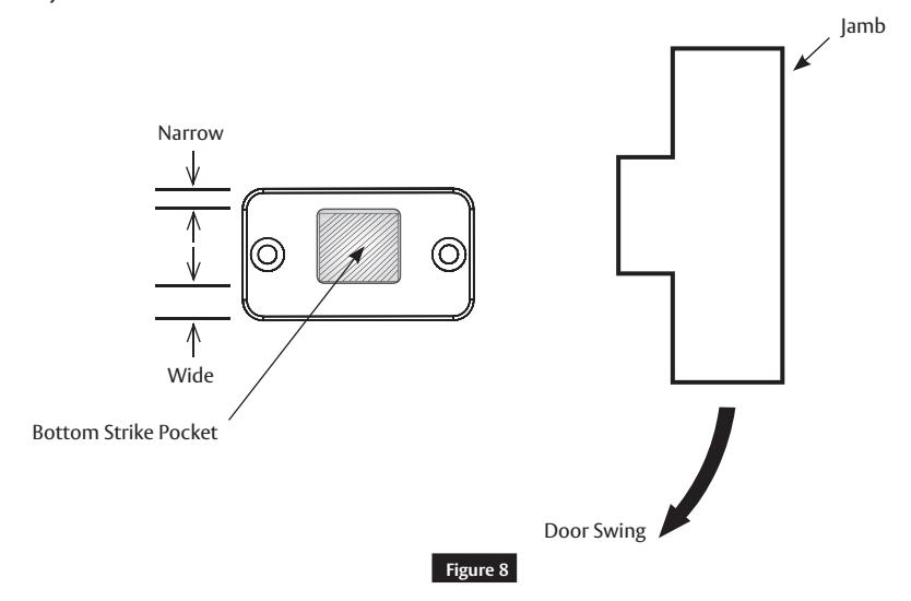
Note
The strike is not symetric. Install as shown. If needed, the strike can later be rotated to increase bolt clearance. ( Figure 8 )
FE6600 Series
Installation Instructions

3 Installation (cont.)
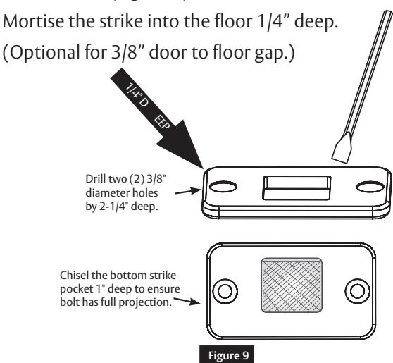
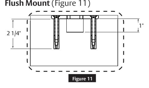
g Install Bottom Strike (cont.)
Flush Mount (Figure 9)
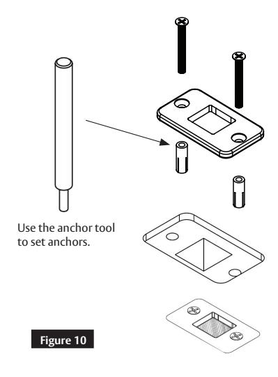
IMPORTANT
Use a vacuum or compressed air to clear holes of debris. ( Figure 10 )
Cross Sectional View
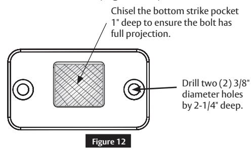
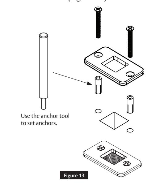
Surface Mount (Figure 12 )
IMPORTANT
Use a vacuum or compressed air to clear holes of debris. ( Figure 13)
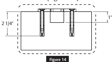
Cross Sectional View Surface Mount (Figure 14 )

3 Installation (cont.)
h Top and Bottom Latch Adjustment
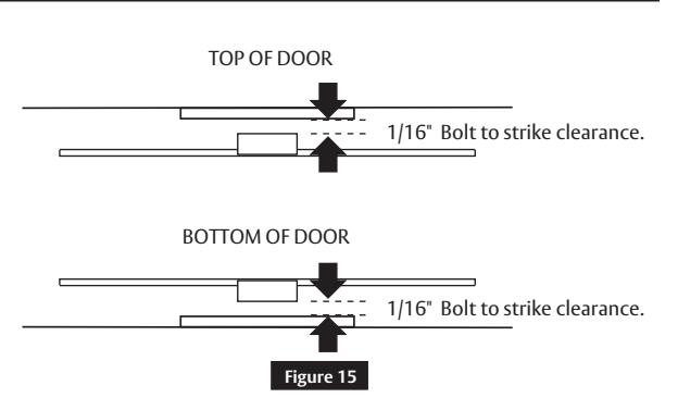
• With the door hung, measure the clearance between the top and bottom bolts and strikes. ( Figure 15)
Note
If both measurements equal 1/16" proceed to Step 3 i , otherwise proceed with Step 3h as follows:
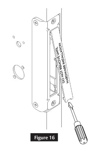
- Remove the mortise filler cap and discard. ( Figure 16)
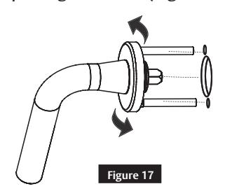
- Retract the latches by roting the lever and opening the door. (Figure 17 )
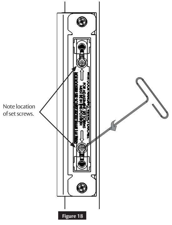
• Using the supplied 1/8" Allen wrench, loosen the set screw 1/4 turn maximum. This allows hex rods to rotate during the latch bolt adjustment. (Figure 18 )
Copyright © 2017, 2019, ASSA ABLOY Access and Egress Hardware Group, Inc. All rights reserved. Reproduction in whole or in part without the express written permission of ASSA ABLOY Access and Egress Hardware Group, Inc. is prohibited.
FE6600 Series
Installation Instructions

1/16" Bolt to strike clearance.
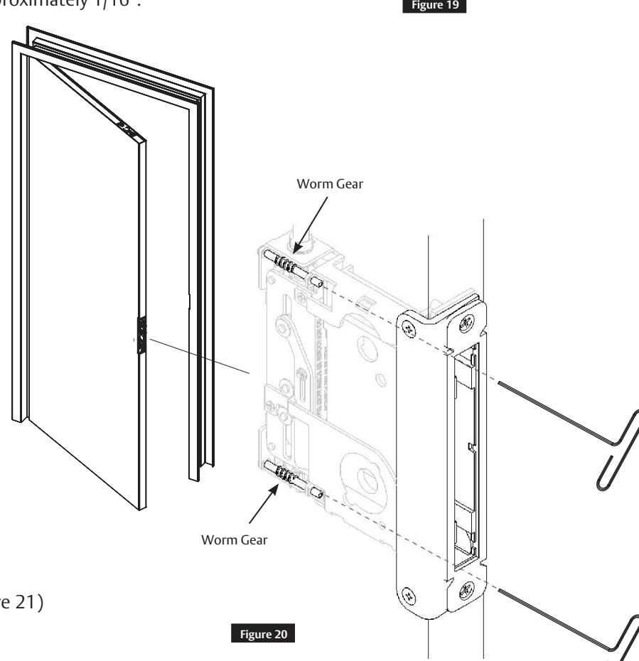
3 Installation (cont.)
h Top and Bottom Latch Adjustment (cont.)
Using the supplied 3/32" Allen wrench, rotate the top or bottom worm gears according to the directions below ( Figure 19 ). Bolt to strike clearance should equal 1/16". This sets the bolt projection. ( Figure 20 )
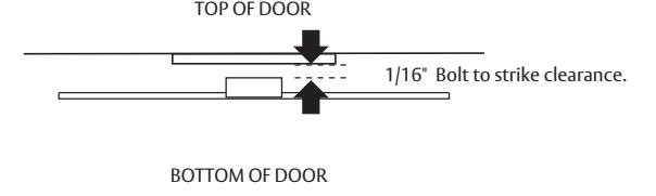
NOTE
Ten (10) turns equals approximately 1/16".
Rotate the top: counterclockwise to project the bolt; clockwise to retract the bolt.
Rotate the bottom: counterclockwise to retract the bolt; clockwise to project the bolt.
NOTE
Latches have bottomed if worm gears click.
Tighten set screws. ( Figure 21 )
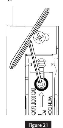
IMPORTANT
Set screws must be fully tightened after adjustment.

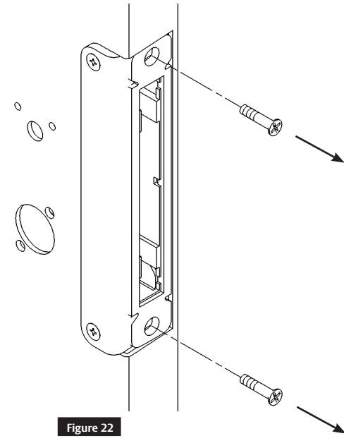
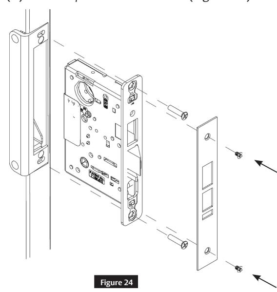
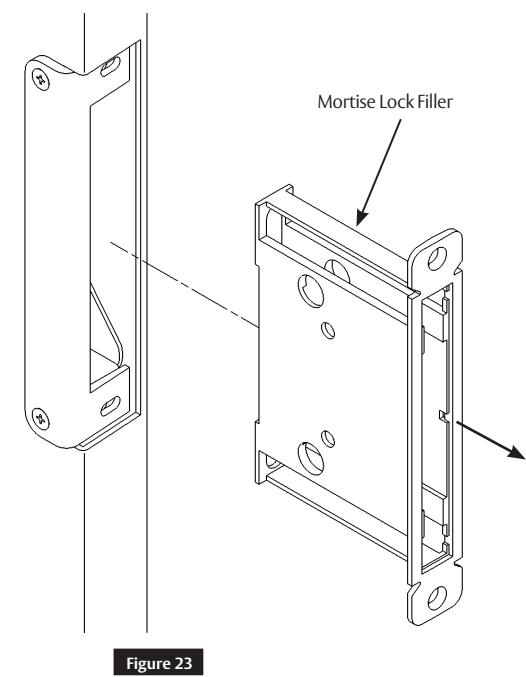
3 Installation (cont.)
i Mortise Lock Install
• Remove the two (2) #12-24 x1" flat head mounting screws. ( Figure 22)
• Remove the mortise lock filler and discard. ( Figure 23)
• Install the mortise lock, two (2) #12-24 x1" flat head mounting screws, outside front, and two (2) #8-32 x1/4" flat head screws. ( Figure 24 )

3 Installation (cont.)
j Final Mortise Lock and Trim Installation
Follow the supplied mortise lock installation instructions for trim and other function related hardware.
k Electronic Access Control (EAC) Reader and Controller Installation
Follow supplied EAC Installation Instructions (if applicable).
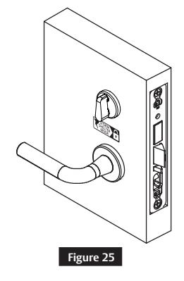
l Deadbolt Label Installation
Install the deadbolt label on the inside of the door. (Figure 25 )
m Key Override With Deadbolt Function Operation Check
Verify hand and bevel of door to determine direction to rotate key and lever. Stand on outside of locked door when determining door hand. (Figure 26)
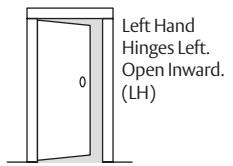
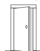
Left Hand Reverse Bevel Hinges Left. Open Outward. (LHRB)
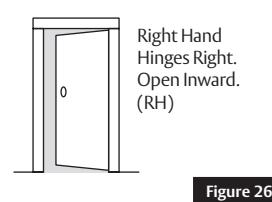
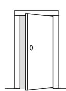
Right Hand Reverse Bevel Hinges Right. Open Outward. (RHRB)
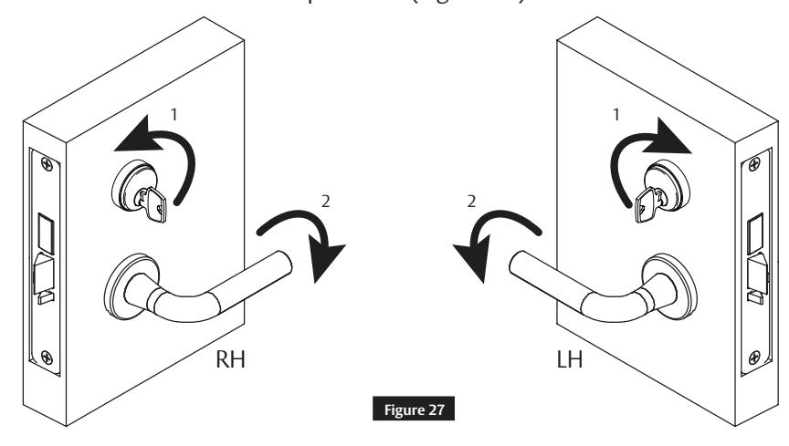
- 1. Rotate key to retract latch and hold. (Do not touch lever).
- 2. Continue holding key, rotate lever with other hand and open door. (Figure 27)
Note
Graphic is for reference only; it does not represent all door hand options.

3 Installation (cont.)
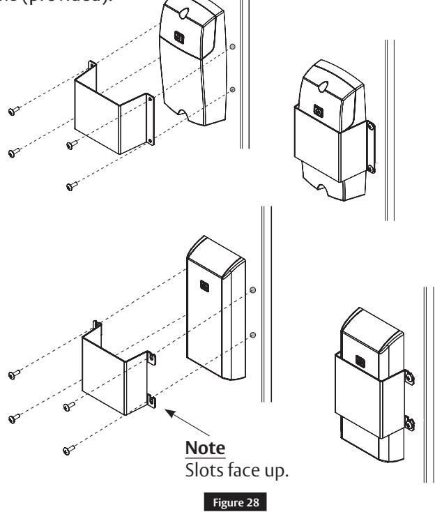
n Electronic Access Control (EAC) Shield (if applicable)
• Install the shield (provided) over the inside controller. (Figure 28 )
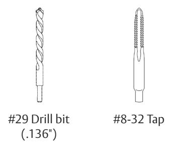
• Drill and tap the door for #8-32 machine screws (provided).
IMPORTANT
The shield MUST be centered on the controller.
4 Optional Installation
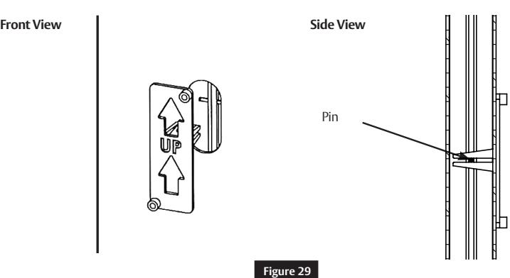
a Dogging Indicator Installation
- • Ensure the door is latched and all bolts are projected.
- Place the plastic field template on the pin in the top rod through the oval cut-out in the door. ( Figure 29)

4 Optional Installation (cont.)
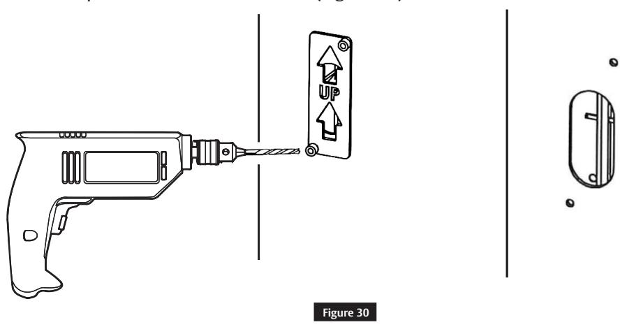
a Dogging Indicator Installation (cont.)
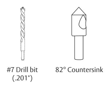
• Using a #7 drill bit, drill two (2) holes completely through the door, making sure the drill remains square to the face of the door. ( Figure 30 )
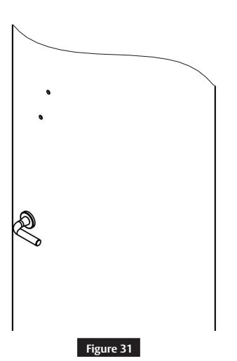
• Countersink holes on the opposite face of the door to fit the supplied oval head screws. (Figure 31)

4 Optional Installation (cont.)
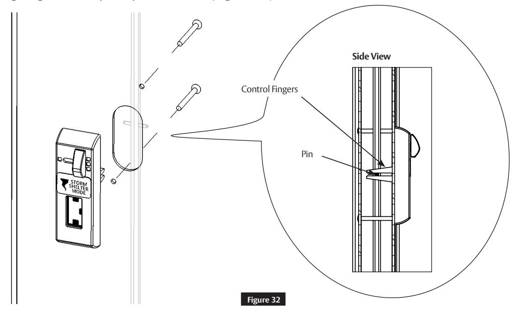
a Dogging Indicator Installation (cont.)
Install the indicator on the inside of the door using supplied 10-24 x 2" oval head screws. Make sure the control fingers grab the top rod pin as shown. (Figure 32 )
Check for proper operation. Rotate the lever until the indicator window shows a single latch point. (Figure 33 )
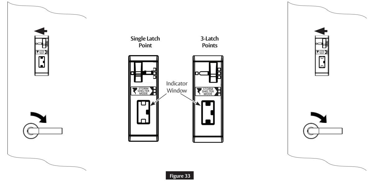
Note
To dog the top and bottom latches in a retracted state, fully rotate the lever and move the slider on the indicator to the left.

5 Addendum
This addendum is to be used as a reference for pre-installed hardware (latches and cassette). The following steps are for ease of reference as they have been completed in advance by the door manufacturer.
a Check Door
Verify the door is:
- Correct size and hand for opening.
- Correctly prepared to Template 4740.
IMPORTANT
If measurement is incorrect, DO NOT PROCEED WITH INSTALLATION. Contact door manufacturer.
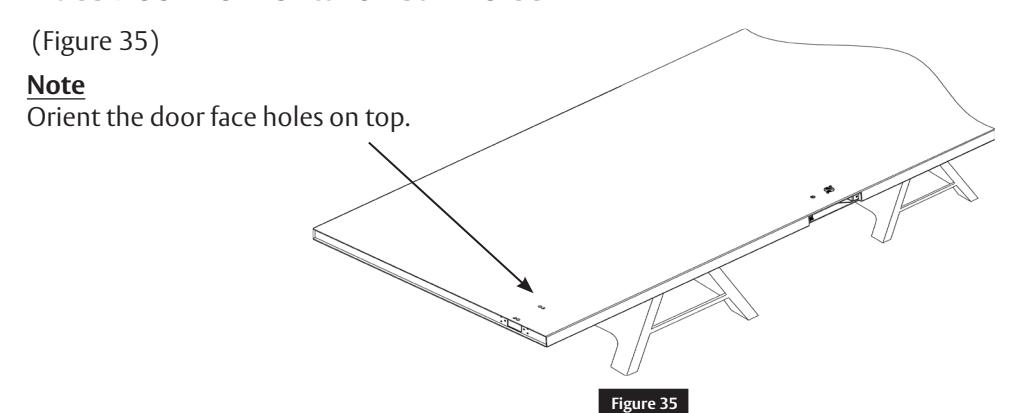
b Place Door Horizontal on Sawhorse

LBC Gear
5 Addendum (cont.)
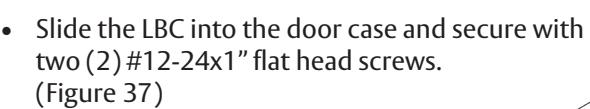
c Install Lockbody Cassette
• Using the supplied 3/32" Allen wrench, rotate both Lockbody Cassette (LBC) worm gears to align slots in the LBC gears to the orientation shown. ( Figure 36)
Alignment is needed for proper installation of the rod guide. (Step 3 h )
Slot
Note
Worm Gear
Figure 36
Worm Gear
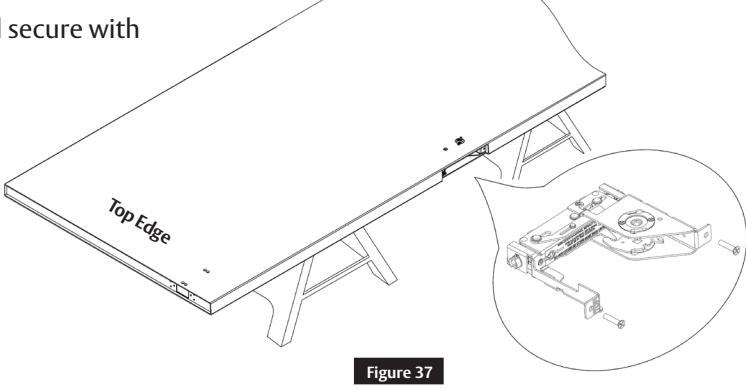
d Latch Rod Guides
• Rod guides help installation by directing the rod into location in the LBC within the door cavity.
Guide
• Pull rod guides away from latches on both rods until they stop. (Figure 38 )

face holes.
5 Addendum (cont.)
e Feed Top Rod into Door
• Orient the latch chassis as shown. Rotate the rod and rod guide so the rod Guide Tab faces up. Slide the rod assembly into the door. Make sure the rod guide remains in the correct orientation with the Guide Tab facing up. ( Figure 39) Guide Tab Latch chassis holes to mate with door Top Edge
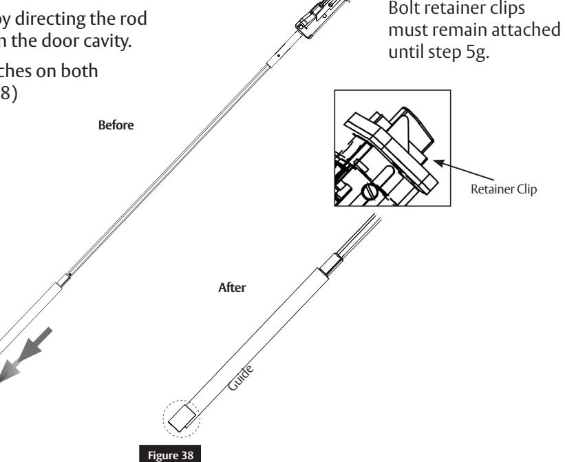
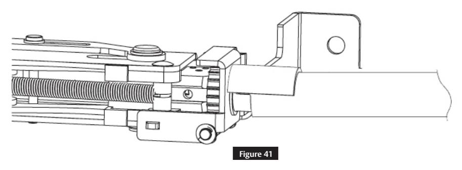
f Align with LBC
• When approaching the LBC, slightly elevate the rod and slide the Guide Tab on outer diameter of the
Figure 39
• To align the hex of rod with the hex of the LBC gear, fit the rod guide tab into the LBC gear slot. Once aligned, push the rod assembly in until fully seated. ( Figure 41)
FM440 03/19

5 Addendum (cont.)
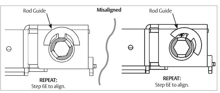
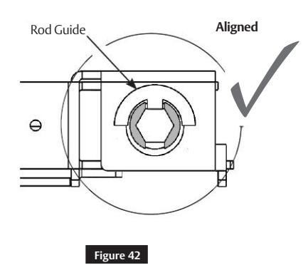
g Troubleshoot Latch Installation
• If the latch will not fully seat in the door, rod or rod guide is not aligned properly with LBC gear. (Figure 42 )
h Correct Rod Installation Check
• Be certain a portion of the red end of the rod can be seen in the LBC viewing window and set screw is in the location shown. ( Figure 43)
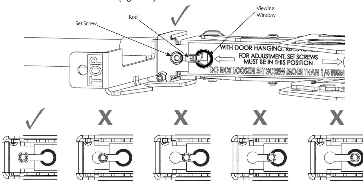
Figure 43
FM440 03/19

5 Addendum (cont.)
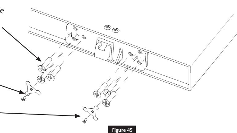
i Secure Top Latch
• Install four (4) 10-24 oval head screws on the face of the door. ( Figure 44)
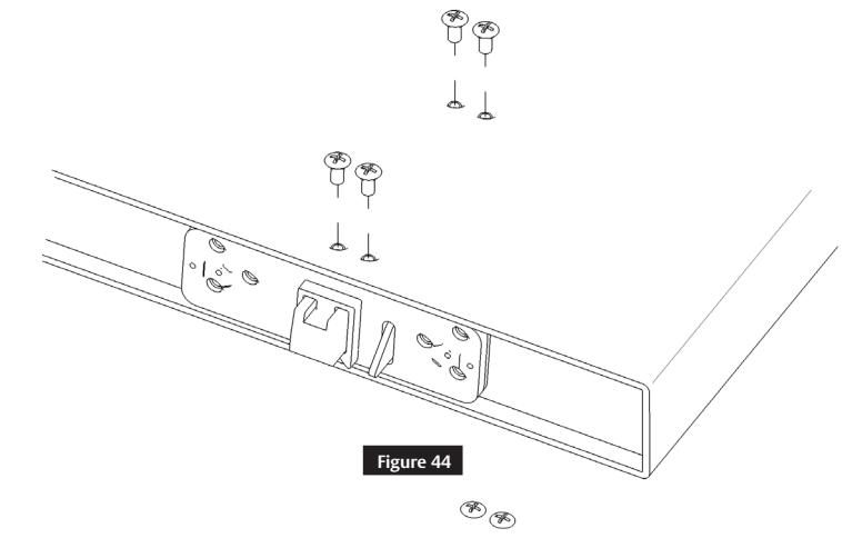
• Install six (6) 1/4-20 flat head screws in the top edge of the door. ( Figure 45 )
Note
Do not fully tighten until all screws are installed.
- Install two (2) screw retainers (top latch only).
- Install two (2) #4-40 flat head screws (top latch only).
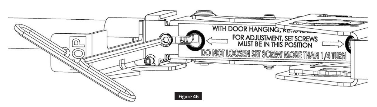
j Tighten Set Screw
Using the supplied 1/8" Allen wrench, tighten the set screw to secure the rod to the LBC. ( Figure 46)
IMPORTANT
Latches will not retract if the set screw is not tightened.
FE6600 Series
Installation Instructions

5 Addendum (cont.)
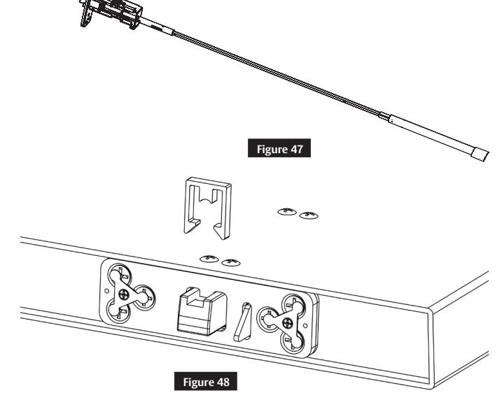
k Bottom Latch Installation
REPEAT
Steps 5e through 5 k to install bottom latch. (Figure 47)
l Check Latch
- Remove the bolt retainer clips from the top and bottom latch assemblies. ( Figure 48)
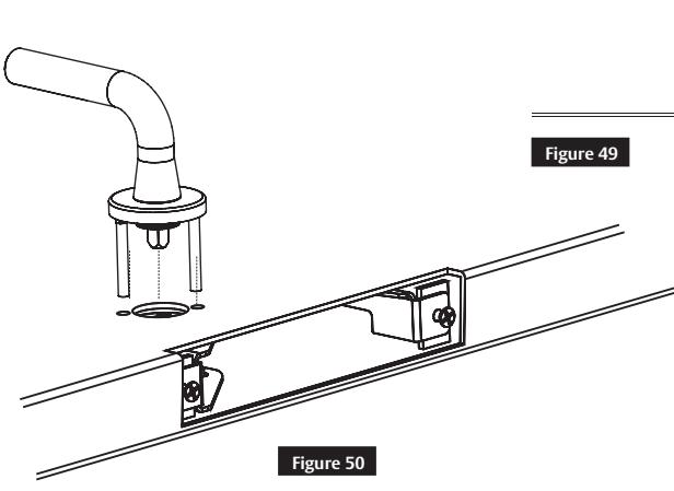
- Insert mortise trim in the door prep and cassette and rotate to verify latches fully retract ( Figure 49 ). Confirm the set screw moves from circle to circle in the LBC viewing window (Figure 50 ). Do not install the mortise lock at this time.
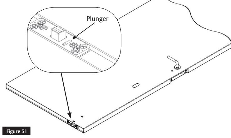
Note
Push the black plunger on the top latch to project bolts. (Figure 51 )

5 Addendum (cont.)
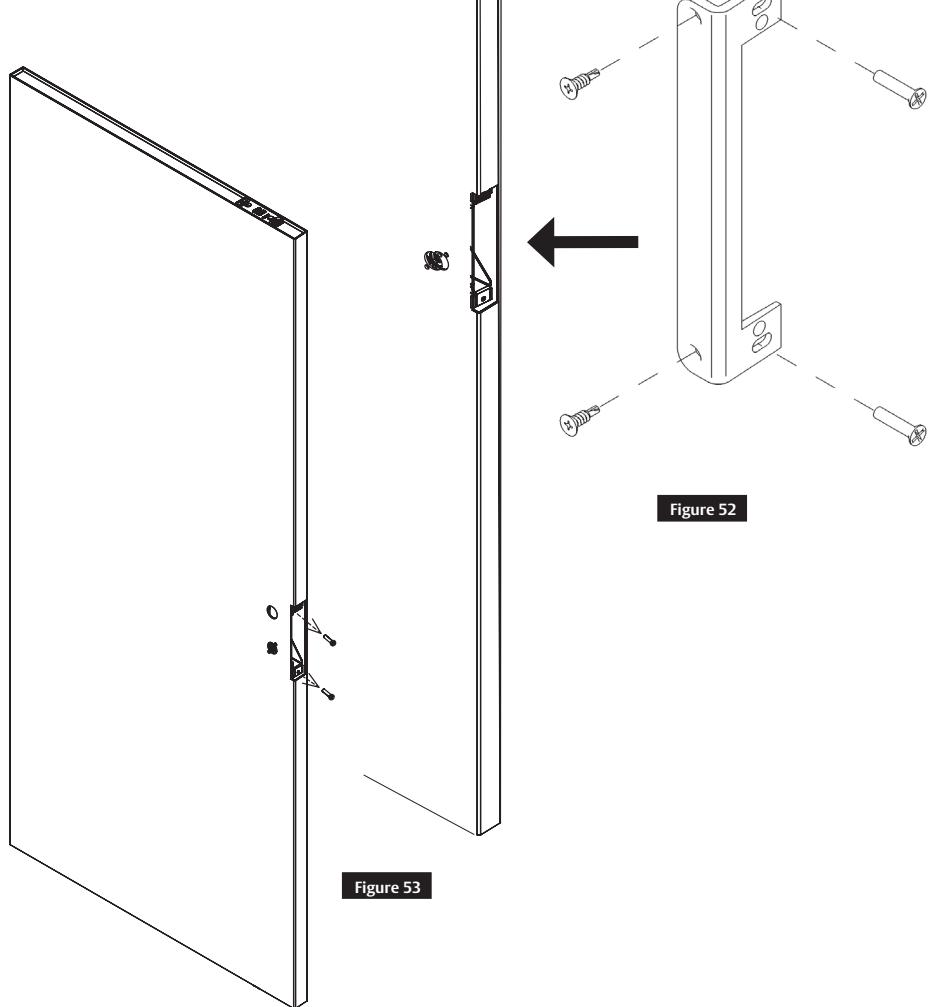
m Mortise Reinforcer and Mortise Lock Installation
- Remove the two (2) #12-24x1" flat head LBC mounting screws that are securing the lockbody case in the door. (Figure 52)
- Place mortise reinforcer into the door.
- Reinstall two (2) #12-24x1" flat head LBC mounting screws (DO NOT FORCE).
- Install two (2) #12x1/4" self tapping screws through mortise reinforcer into the face of the door. ( Figure 53)
NOTE
Reinforcer lip belongs on the side of the door that has a special cutout at the door edge.
n Final Installation
Return to page 1 for final installation.

Corbin Russwin, Inc. 225 Episcopal Road Berlin, CT 06037 USA Phone: 800-543-3558 Fax: 800-447-6714 www.corbinrusswin.com
ASSA ABLOY is the global leader in door opening solutions, dedicated to satisfying end-users needs for security, safety, and convenience