


Installation Instructions

F1857ET, P1850ET, P1857ET
ED2000 Exit Device Trim

Dummy Trim F02 : (Not for fi re exit) Door pull when device is dogged.


F03 : Key retracts bolt(s). NON-HANDED : Horizontal keyway
F1857ET & P1857ET Trim : Attach cylinder to trim prior to installation on the door. See page 2. P1850ET Trim : No pre-asssembly required. Trim is shipped read to be installed.
WARNING
This product can expose you to lead which is known to the state of California to cause cancer and birth defects or other reproductive harm. For more information go to www. P65warnings.ca.gov.
WARNING
Attention Installer: Improper installation may result in damage to the product and void the factory warranty.
Exit Trim
F1857ET, P1850ET, P1857ET
Installation Instructions
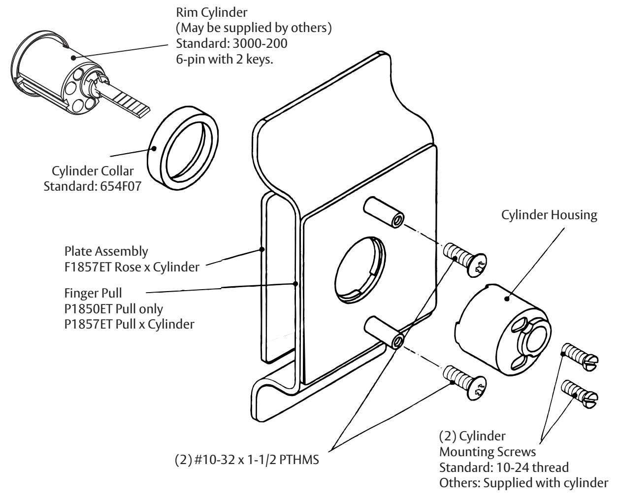
Cylinder Assembly
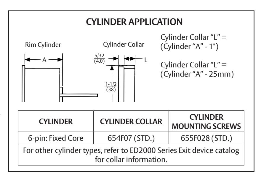
- 1. Check cylinder components. See chart. Non-standard cylinder collars and mounting screws must be supplied with optional cylinders.
- 2. Assemble cylinder (note horizontal keyway). Insert Cylinder Housing prongs into Escutcheon matching notches. Pass Cylinder tailpiece thru Cylinder Collar and Cylinder Housing hole. Bolt Cylinder seated in Cylinder Collar recess (DO NOT OVERTIGHTEN SCREWS).
- 3. Check cylinder action. Cylinder key must freely rotate tailpiece when turned in either direction.
Exit Trim
F1857ET, P1850ET, P1857ET
Installation Instructions
Trim for RHR or LHR door, as packed .
STOCK DOORS :
Installation shows preparation for exit device trim. Stock door with ANSI/BHMA A156.115 preparation, for cylindrical lock with 2-3/4 (70) backset, may be used as substitute, when Trim is used with rim or SVR device.
- 1. Check box contents. (See other side for box components and assembly instructions).
- 2. Carry "Vertical Reference Centerline" to outside door face. Follow steps 2a and 2b, at right.
- 3. Carry "Horizontal Reference Centerline" from inside to outside door face. STD 161 Door Prep Acceptable.
- 4. Align trim template and tape to door, outside face. Non-Handed Trim Installer preference for cylinder/key direction will determine position of 1/4" offset for cutout.

CAUTION: Offi ce copiers and facsimile machines may change the size of a drawing and make the template inaccurate to use as a door marker. If this is not the original template packed with the trim, use only the dimensions written on the template to locate the holes on the door (do not use the template as a door marker).
- 5. Spot holes and prepare door for trim.
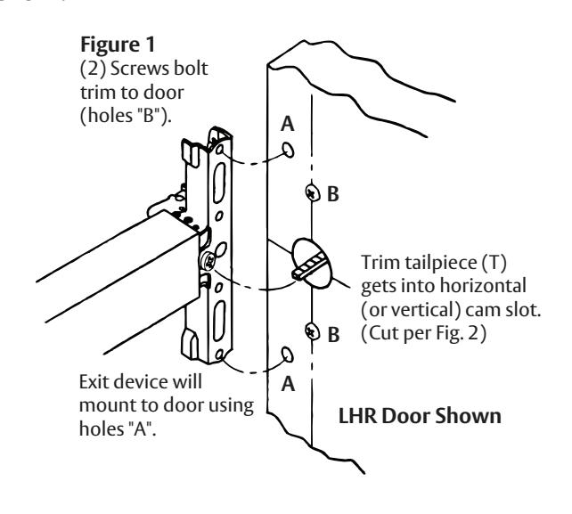
- 6. Mount trim to door. Fasten fi nger tight with with 2 #10-32 x 1-1/2" PTH machine screws (See Figure 1). NOTE: If installing 214F dummy trim, continue as shown in device instructions.
- 7. With trim in place, cut trim tailpiece as shown in Figure 2.
- 8. Seat device so that trim tailpiece penetrates cam slot as shown in Figure 1. Continue as shown in device instructions.
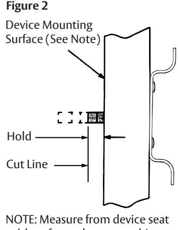
(door face - shown - or shim surface) Dimensions are in inches (mm).

