| Branding Guidelines For Installation Instruction Sheets | |
|---|---|
| Endorsed Logo | |
| * Must Be Used On All Single Page and Multiple Page Installation Instruction Sheets | |
- Group Brand Tagline
- * Must Be Used On The Bottom Left Of ALL ONE PAGE Installation Instruction Sheets
- * Must Be Used On The Bottom Left Of ALL INSIDE PAGES of Multiple Page Installation Instruction Sheets * It is NOT USED On The Back Page Or Back Cover Of Installation Instruction Sheets
-
* Image Must Be Used CANNOT Be Typed
- Corporate Statement * Must Be Used On The BACK PAGE Or BACK COVER Of All Multiple Page Installation Instruction Sheets * Image Must Be Used - CANNOT Be Typed
-
* A 2 line Version and a 5 Line Version Of The Corporate Statement Image Are Available

* Image Must Be Used - CANNOT Be Typed
Reproduction in whole or in part without the express written permission of Corbin Russwin, Inc. is prohibited.
FM 492 7/12 FM 492 12/18

* Must Be Used On The Bottom Left Of ALL ONE PAGE Installation Instruction Sheets
* It is NOT USED On The Back Page Or Back Cover Of Installation Instruction Sheets * Image Must Be Used - CANNOT Be Typed
|
* Image Must Be Used - CANNOT Be Typed
* A 2 line Version and a 5 Line Version Of The Corporate Statement Image Are Available |
* Must Be Used On The BACK PAGE Or BACK COVER Of All Multiple Page Installation Instruction Sheets |
Corporate Statement
* Must Be Used On The BACK PAGE Or BACK COVER Of All Multiple Page Installation Instruction Sheets * Image Must Be Used - CANNOT Be Typed |
|---|---|---|
| * A 2 line Version and a 5 Line Version Of The Corporate Statement Image Are Available | ||
* Must Be Used On The Bottom of The BACK PAGE OR BACK COVER Of All Multiple Page Installation Instruction Sheets * Must Be Used On The Bottom of ALL ONE PAGE Installation Instruction Sheets * Must Be Used On The Bottom of The BACK PAGE OR BACK COVER Of All Multiple Page Installation Instruction Sheets
Copyright © 2008 Corbin Russwin, Inc., an ASSA ABLOY Group company. All rights reserved.
Reproduction in whole or in part without the express written permission of Corbin Russwin, Inc. is prohibited.
Branding Guidelines For Installation Instruction Sheets
* Must Be Used On All Single Page and Multiple Page Installation Instruction Sheets
Group Brand Tagline * Must Be Used On The Bottom Left Of ALL ONE PAGE Installation Instruction Sheets * Must Be Used On The Bottom Left Of ALL INSIDE PAGES of Multiple Page Installation Instruction Sheets * It is NOT USED On The Back Page Or Back Cover Of Installation Instruction Sheets
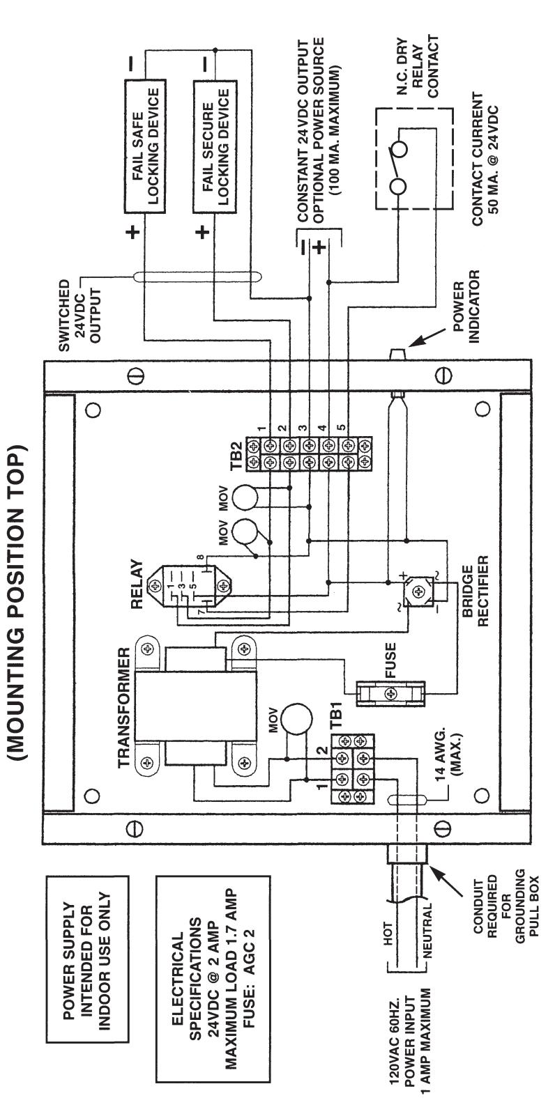
780 FIRE RELEASE POWER SUPPLY INSTALLATION INSTRUCTIONS
INSTALLATION
The 780 enclosure should be securely fastened to the Symptom : 120V is applied to TB1. There is no voltage wall using the four 1/4 inch diameter mounting holes located in the back of the box. Position the enclosure so that the transformer is facing towards the top. Do not obstruct the view of the power indicator. The 780 must not be installed outdoors. It can be located in the plenum or in an equipment room. To minimize wire run lengths, it is recommended that the 780 be installed as close to the electric locking device(s) as possible.
For the 120VAC power input, terminal TB1 will accommodate up to 14 gauge wire. Conduit must be used to provide an adequate earth ground to the enclosure.
The 780 is designed to be used with locking devices Symptom: 120V is applied to TB1, but 24VDC is not requiring a 24VDC Power Source. The number of locking devices used with the 780 depends on the current draw of the locking device and the current capacity of the fire release power supply. The Series 780 comes with 2 amp capacity. The total load must not exceed the maximum load specified on the wire diagram (located underneath the fire release power supply cover plate).
OPERATION
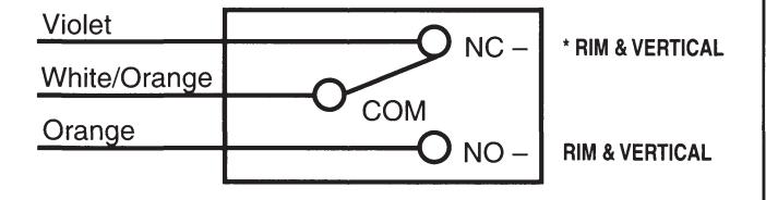
When 120VAC power is applied to the 780 and connection is made from TB2, terminals 4 & 5 to the fire alarm normally closed contacts, the output across TB2, terminals 1 and 3 will produce an unregulated, unfiltered 24VDC, plus or minus 3V, depending on the size of the applied load. Use this output for all fail safe locking devices. There will be no voltage across terminals 2 and 3 of TB2, which is used as the output for all fail secure locking devices.
/ WARNING
This product can expose you to lead which is known to the state of California to cause cance and birth defects or other reproductive harm. For more information go to www.P65warnings.ca.gov
08/2018
TROUBLESHOOTING
across terminals 1 and 3 of TB2, but there
is voltage across terminals 2 and 3.
Cause: 1. The 780 fire alarm input is not connected to the fire alarm.
2. The input is connected to the N.O. contacts instead of the N.C. contacts of the fire alarm.
3. An open wire or loose connection within the wiring to the fire alarm.
present at TB2, terminals 1 and 3 or 2 and 3.
Cause: 1. Field wires to the load are shorted together against the conduit, door frame or electrical hinge (If used).
2. The applied load has exceeded the rating of the fuse.
Check for a blown fuse.
WARNING: ALWAYS REPLACE WITH THE SAME SIZE FUSE. INSTALLING A FUSE THAT EXCEEDS THE RATING OF THE ORIGINAL FUSE WILL BLOW THE INTERNAL FUSE OF THE TRANSFORMER AND VOID THE WARRANTY. THE TRANSFORMER CAN NO LONGER BE USED AND MUST BE SENT BACK TO THE FACTORY FOR REPLACEMENT.
In U.S.: Corbin Russwin, Inc 225 Episcopal Road Berlin, CT 06037 USA Phone: 800-543-3658
Technical Product Support
Phone: 888-607-5703
In Canada: ASSA ABLOY Door Security Solutions Canada 160 Four Valley Drive Vaughan, Ontario, Canada L4K 4T9 Phone: 800-461-3007
SUPPLY DIAGRAM FOR POWER TYPICAL WIRING RELEASE 780 FIRE