


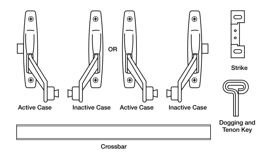
ED7200 Series
Reversible Rim
Exit Devices
Important:
- Check hand of fixture. If hand of fixture needs reversing, see "To Reverse Hand of Device".
- If using removable mullion, see template packed with mullion.
Installation Instructions

1
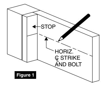
Mark Stop
See Template
1. Mark stop with centerline of strike and strike mounting holes. (Figure 1)
Note: Centerline of strike is 4-5/8" higher than desired height of crossbar.
Transfer horizontal centerline of strike to inside of door at hinge and latch side. (Figure 1)
2
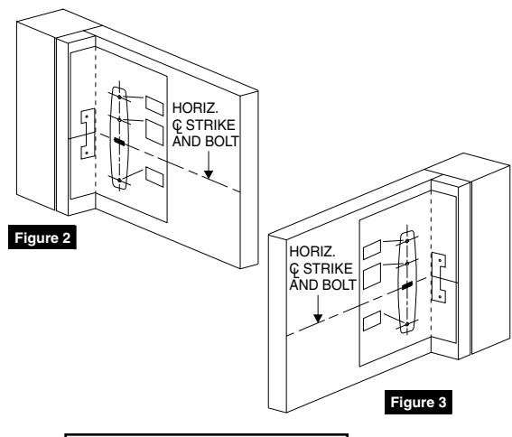
Spot Case, Trim and Strike Mounting Holes
Active Case (Figure 2)
- 1. Fold bolt template toward you on dotted line and place in INSIDE of door against stop.
- 2. Line up horizontal centerline marked on door.
- 3. Spot and drill holes for bolt and 668A strike.
Inactive Case (Figure 3)
- 1. Position opposite edge of template against stop, folding on dotted line.
- 2. Line up horizontal centerline marked on door.
- Spot and drill holes for case mounting screws only.
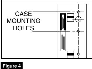
Trim (Figure 4)
- 1. Position rim template on outside of door.
- Carefully check trim function before spotting and drilling only those holes for your trim function.
2
Prepare Cases For Mounting
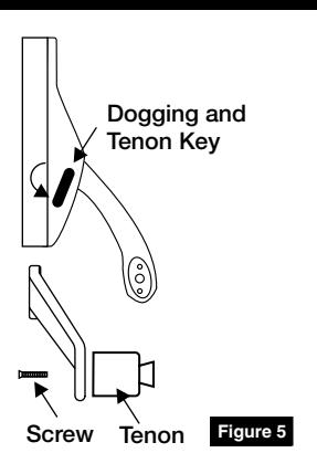
- If bolt has dogging function, undog cases using furnished key in side of case by loosening lock-down screw. (Figure 5)
- 2. Using key furnished, back out screw and remove crossbar tenon from active case lever. (Figure 5)
Reversible Rim Device
Installation Instructions

4 Mount Cases
1. If installation has no outside trim, mount active case on prepared door using thru-bolts and sex nuts furnished.
NOTE: See trim template for trim and active case assembly and mounting on door.
- 2. Mount inactive case using thru-bolt and sex nuts furnished.
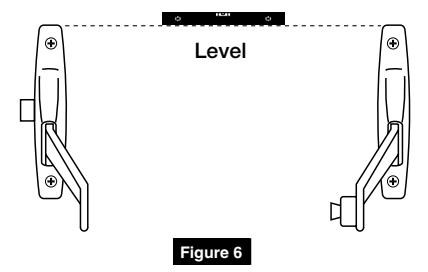
- 3. Be sure cases are level. (Figure 6)
5 Install Crossbar
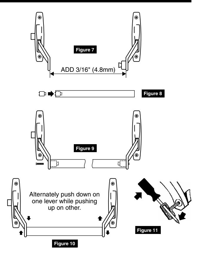
- 1. Measure distance between bottom of levers then add 3/16" (4.8mm) and cut crossbar to this measurement. (Figure 7)
- 2. Remove burrs on inside/outside of bar.
- 3. Place tenon removed from active case into end of crossbar so it is just flush with end of bar. (Figure 8)
- 4. Place open end of bar over tenon secured to inactive case lever. Set bar into recess in lever. If bar won't fit easily over tenon, loosen screw and tap head of screw with mallet.
- 5. Position other end of bar in recess in active case lever then thread screw into tenon finger-tight. (Figure 9)
- 6. Rock crossbar to Seat bar in lever by alternately pushing down on one lever while lifting on other. Rocking will assure alignment of two (2) tenon pins in lever holes. (Figure 10)
- 7. Secure screws using screwdriver through bow of dogging key furnished. (Figure 11)
NOTE: If crossbar does not work freely, check installation for binding of levers due to improper bar length or case misalignment.
6 Mount Strike
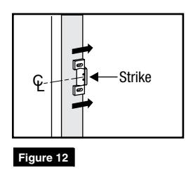
1. Using holes marked on stop in Step 1, mount strike. Be sure centerline of strike lines up with centerline of bolt. (Figure 12)
NOTE: To obtain proper latching position, adjust strike so that bolt latches tightly without binding.

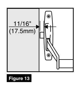
7 Test Operation of Bolt
- 1. Latch should project 11/16" (17.5mm) when crossbar is in neutral position. (Figure 13)
- 2. Latch is held retracted when key is turned clockwise 90° until key is turned back to original position.
- 3. Latch is held retracted when key is turned clockwise 360° and key is removed.
- 4. Latch is held retracted when crossbar is pushed down and dogging key (if furnished) is inserted into each case hole and tightened securely.
8 To Reverse Hand of Device
Note: To simplify reversing, place as shown (Figure 14). Do not change position of cases or covers except as shown.
Remove Case Covers
1. Remove screws at top and bottom of back of each case.
To remove active case cover:
- a. Hold latch depressed.
- b. Hold case lever up.
- 2. Using screwdriver, pry nylon button from inside of inactive case cover (Cover B) and replace it in hole in back of active case cover (Cover A). (Figure 15)
- 3. To reverse latch retractor assembly, depress latch bolt with finger then lift out assembly and reposition in opposite end of active case so that slot in latch retractor engages pin in back of latch. (Figure 16)
- 4. Reassemble covers and cases. (Figure 17)
Active
- a. Depress bolt with finger.
- b. Lift lever up and slide cover into . . position so that lever finger . . engages pin in back of latch and . . tube in latch retractor assembly . . fits into hole in back of cover.
Inactive
Reposition cover and replace screws.
Corbin Russwin 225 Episcopal Road Berlin, CT 06037 Phone: 800-543-3658 Fax: 800-447-6714 corbinrusswin.com
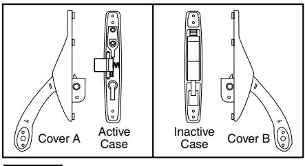
Figure 14
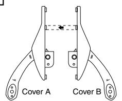
Figure 15
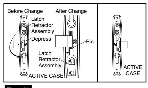
Figure 16
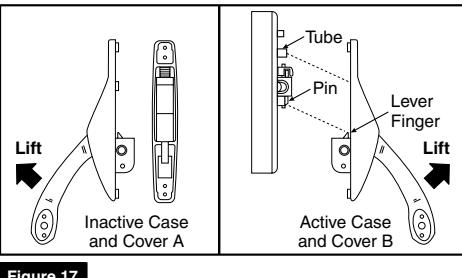
Figure 17
For installation assistance contact Corbin Russwin 1-800-543-3658 • techsupport.corbinrusswin@assaabloy.com
permission of Corbin Russwin, Inc. is prohibited.
Copyright © 2018 Corbin Russwin, Inc., an ASSA ABLOY Group company. All rights reserved. Reproduction in whole or in part without the express written