Installation Instructions

ED7200 Series
Reversible Rim Exit Device

Crossbar
Important:
- Check hand of fixture. If hand of fixture needs reversing, see "To Reverse Hand of Device".
- If using removable mullion, see template packed with mullion.
WARNING
This product can expose you to lead which is known to the state of California to cause cancer and birth defects or other reproductive harm. For more information go to www. P65warnings.ca.gov.
WARNING
Attention Installer: Improper installation may result in damage to the product and void the factory warranty.
Reversible Rim Device
Installation Instructions


Mark Stop
See Template
1. Mark stop with centerline of strike and strike mounting holes. (Figure 1)
Note: Centerline of strike is 4-5/8" higher than desired height of crossbar.
2. Transfer horizontal centerline of strike to inside of door at hinge and latch side. (Figure 1)

Figure 1
2
Spot case, Trim and Strike Mounting Holes
Active Case (Figure 2)
- 1. Fold bolt template toward you on dotted line and place in INSIDE of door against stop.
- 2. Line up horizontal centerline marked on door.
- 3. Spot and drill holes for bolt and 668A strike.
Inactive Case (Figure 3)
- 1. Position opposite edge of template against stop, folding on dotted line.
- 2. Line up horizontal centerline marked on door.
- 3. Spot and drill holes for case mounting screws only.
Trim (Figure 4)
- 1. Position rim template on outside of door.
- 2. Carefully check trim function before spotting and drilling only those holes for your trim function.


FM460 1/23
Reversible Rim Device
Installation Instructions

3 Prepare Cases for Mounting
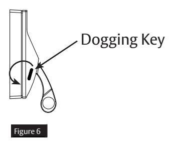
If bolt has dogging function, undog cases using furnished key in side of case byloosening lock-down screw. (Figure 5)
4 Mount Cases
1. If installation has no outside trim, mount active case on prepared door using thru-bolts and sex nuts furnished.
NOTE: See trim template for trim and active case assembly and mounting on door.
- 2. Mount inactive case using thru-bolt and sex nuts furnished.
- 3. Be sure cases are level. (Figure 6)

Reversible Rim Device
Installation Instructions

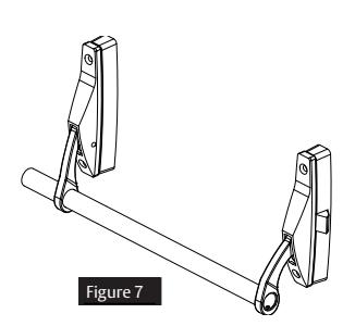
5 Install Crossbar
- 1. Slide bar through active and inactive case with screw hole towards active case. Screw plug and bar onto active case with 10-24 x 3/4" cap screw. (Figure 7)
- 2. Mark bar at inactive case & cut. Length of cross bar should be from flush to 1/16" less than flush. (Figure 8)


- 3. Drill 3/16" hole thru one side of bar using hole in arm to locate. (Figure 9)
- 4. Slide plug into bar with holes aligned and attach with 10-24 x 3/4" cap screw. (Figure 10)


NOTE: If crossbar does not work freely, check installation for binding of levers due to improper bar length or case misalignment.
For installation assistance contact Corbin Russwin
Reversible Rim Device
Installation Instructions

6 Mount Strike
Using holes marked on stop in Step 1, mount strike. Be sure centerline of strike lines up with centerline of bolt. (Figure 11)
NOTE: To obtain proper latching position, adjust strike so that bolt latches tightly without binding.

7 Test Operation of Bolt
- 1. Latch should project 11/16" (17.5mm) when crossbar is in neutral position. (Figure 12)
- 2. Latch is held retracted when key is turned clockwise 90° until key is turned back to original position.
- 3. Latch is held retracted when key is turned clockwise 360° and key is removed.
- 4. Latch is held retracted when crossbar is pushed down and dogging key (if furnished) is inserted into each case hole and tightened securely.

Figure 12
5
Reversible Rim Device
Installation Instructions

8 To Reverse Hand of Device
Note: To simplify reversing, place as shown (Figure 13). Do not change position of cases or covers except as shown.
Remove Case Covers
1. Remove screws at top and bottom of back of each case.
To remove active case cover:
- a. Hold latch depressed.
- b. Hold case lever up.
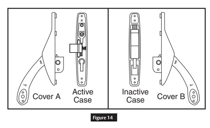
- 2. Using screwdriver, pry nylon button from inside of inactive case cover (Cover B) and replace it in hole in back of active case cover (Cover A). (Figure 14)

Figure 13
Reversible Rim Device
Installation Instructions

8 To Reverse Hand of Device, continued
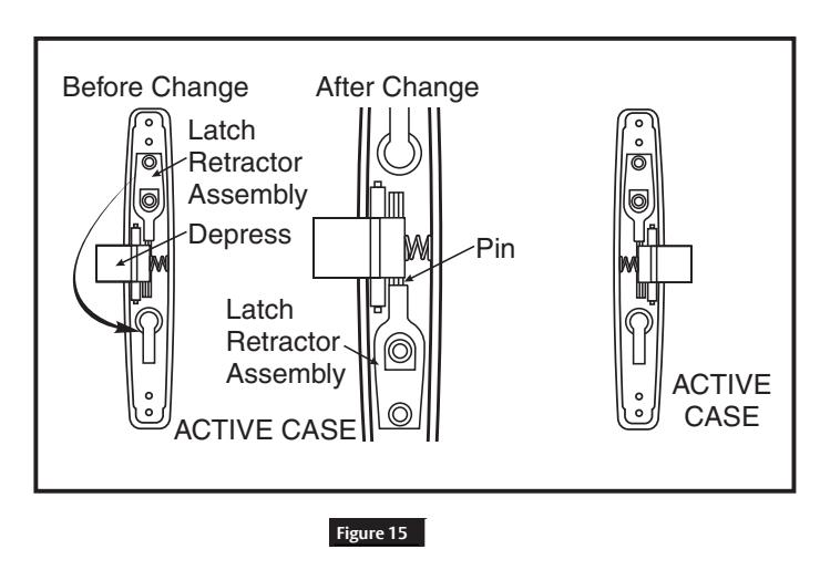
3. To reverse latch retractor assembly, depress latch bolt with finger then lift out assembly and reposition in opposite end of active case so that slot in latch retractor engages pin in back of latch. (Figure 15)
Reassemble covers and cases. (Figure 16)
Active
- a. Depress bolt with finger.
- b. Lift lever up and slide cover into position so that lever finger engages pin in back of latch and tube in latch retractor assembly fits into hole in back of cover.
Inactive
Reposition cover and replace screws.

Figure 16